
Detroit Diesel MTU Series 2000 12V and 16V Engines Service Manual 6SE2000
Original price was: $39.95.$24.95Current price is: $24.95.
The complete Detroit Diesel MTU Series 2000 12V and 16V Engines Service Manual, document 6SE2000, December 2001. 1,746 pages covering construction, industrial, generator set and marine engines – teardown, overhaul, inspection criteria, tolerances and mechanical troubleshooting. Instant PDF download.
Description
The Detroit Diesel MTU Series 2000 12V and 16V Engines Service Manual is the complete workshop documentation for the Series 2000 diesel engine in twelve-cylinder and sixteen-cylinder form, issued under document number 6SE2000 with a December 2001 publication date. It is written for the technical personnel responsible for maintaining and servicing these engines, and it covers the unit as installed in construction, industrial, generator set and marine applications.
At 1,746 pages this is not a quick-reference booklet. It is the full service document, built around a numbered function-group system that takes each assembly from general view and special tools, through removal and disassembly, into inspection and repair with published wear limits, and back out through assembly, installation and after-installation checks. Every task in the book is cross-referenced by group number, so a technician working on the cylinder head can move straight to C 041.05 and follow the same sequence the workshop would.
File Details
- Manual type: Service Manual – disassembly, repair, overhaul, inspection and mechanical troubleshooting
- Brand / publisher: Detroit Diesel Corporation, MTU Friedrichshafen
- Engine series: Series 2000, 12V and 16V
- Applications covered: Construction, Industrial, Generator Set and Marine
- Document number: 6SE2000
- Publication date: December 2001
- Revision marking: 0112
- Language: English
- Page count: 1,746 pages
- File format: PDF
Chapters and Systems Covered
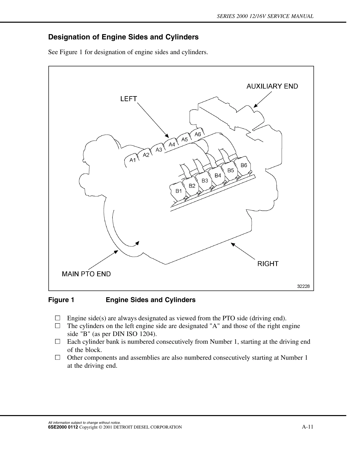
- Section A – General Information: Important Information, Designation of Engine Sides and Cylinders, Torque Specifications for Bolts Clamps and Nuts, Settings, Safety Precautions, Data Sheets, Conversion Tables, Publication Summary, Repairing Threaded Bores
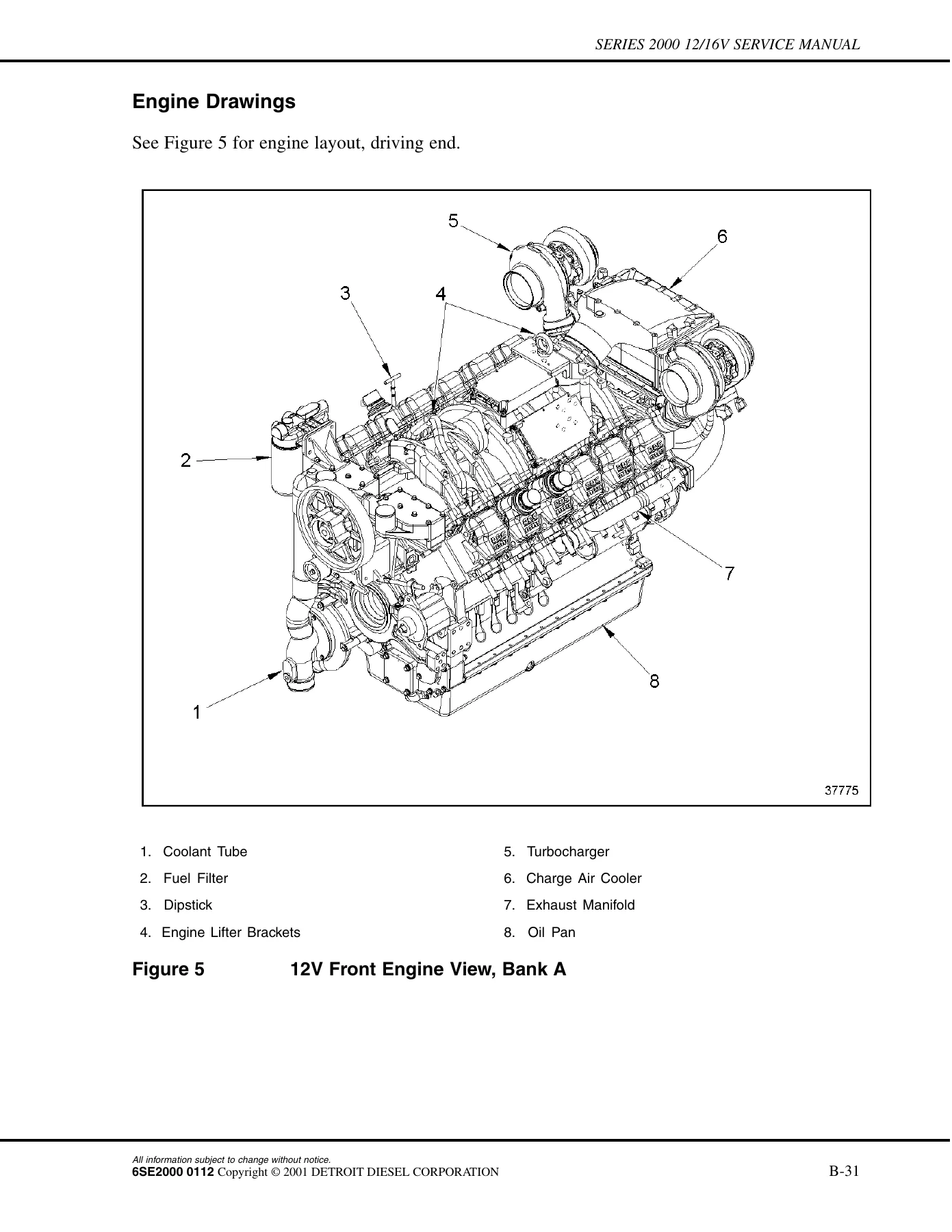
- Section B – Operation Schedules: Verify Engine Condition Before Overhaul, Engine Removal, Engine Removal Procedures, Engine Run-In, Engine Installation and Operation, Engine Drawings, Maintenance Schedule
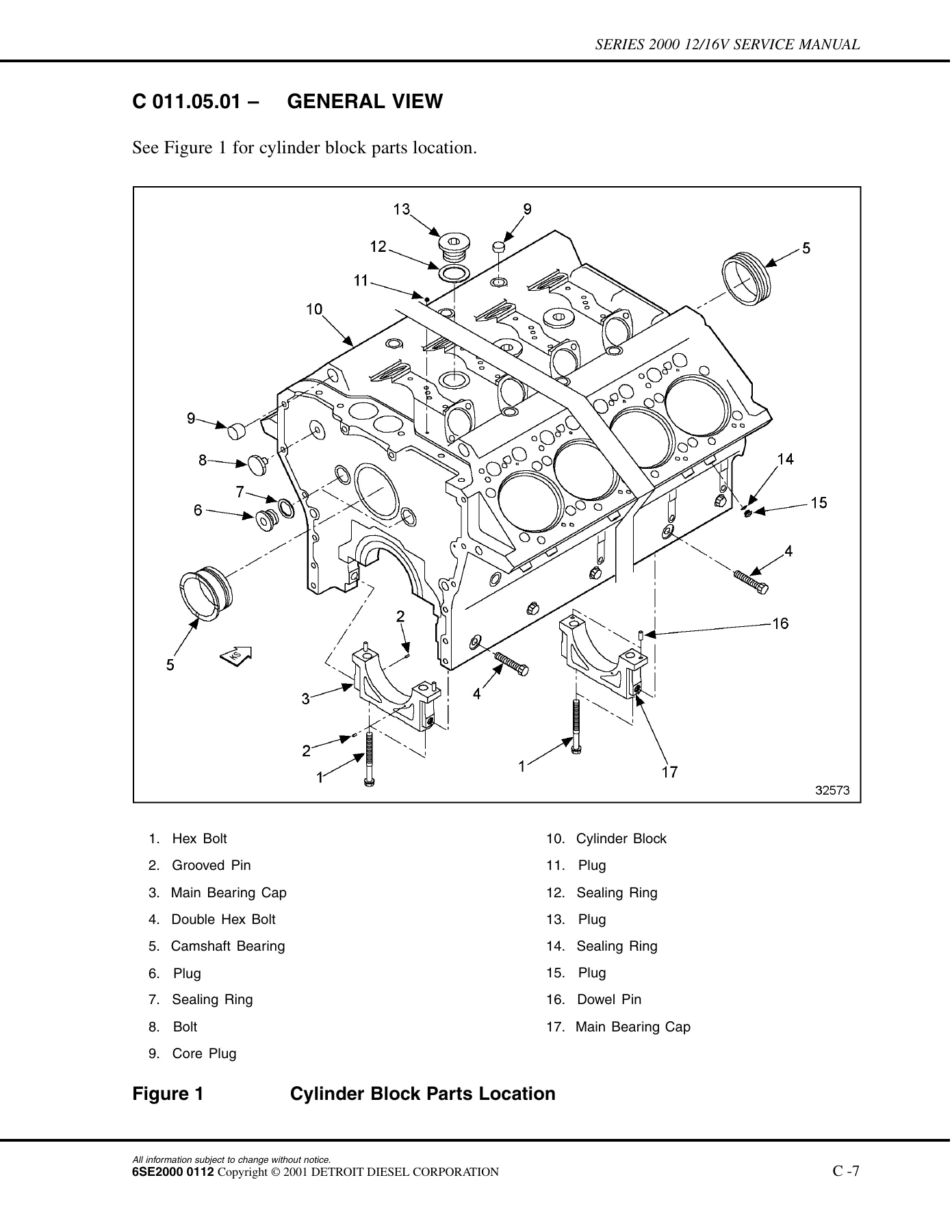
- Section C – Maintenance: C 010 Cylinder Block (cylinder block, cylinder liner, oil pan, engine lifting brackets, marine cylinder block ventilation); C 020 Gear Train (flywheel housing, gear case, drive belts, fan mount); C 030 Running Gear (crankshaft, power take-off driving end, vibration damper, pistons and connecting rods); C 040 Cylinder Head; C 050 Valve Gear (camshaft, camshaft follower and pushrods, valve drive); C 070 High Pressure Fuel System (electronic unit pump, fuel injector nozzle and high pressure fuel lines); C 080 Low Pressure Fuel System (fuel pump, fuel lines, fuel filter assembly, marine fuel filter, Sea Pro 511 fuel processor, fuel rail, delivery line, return line, junction block and bleed lines); C 100 M Exhaust Turbocharger (marine turbocharger and standard turbocharger); C 110 Charge Air Cooler (construction and industrial, marine); C 120 Air Intake and Air Supply (air filter, intake housing, intake manifold, control block and control lines for air and exhaust flow control flaps, shutdown valves); C 140 Exhaust System (exhaust manifold, marine exhaust manifold, exhaust housing with actuator, exhaust housing without actuator); C 170 Starting System (starter); C 180 Lube Oil System (lubrication oil pump, oil lines, oil dipstick and filler neck, oil filter/rotary slide/heat exchanger, oil spray nozzle, turbocharger oil supply and return lines, oil cooler, oil filter assembly); C 200 Cooling System (engine coolant pump, secondary engine coolant pump, engine coolant tubes, marine engine coolant lines, marine vent lines, marine heat exchanger, thermostat housing and transfer housing, coolant distribution housing and thermostat, raw water pump and connecting lines); C 210 Power Supply – Engine Side (marine alternator, construction and industrial alternator); C 230 Engine Mounts (marine engine mounting, trunnion); C 342 M Marine Gear Mounting System; C 500 Electronic Monitoring Systems (construction and industrial electronic control system, engine sensors and wiring harnesses, marine electronic control system, marine engine sensor units and wiring harness, cylinder block heater relay)
- Section D – Tolerance and Wear Limits: General Information, Cylinder Block, Combustion Air System, Exhaust System, Cooling System
- Section E – Troubleshooting: Mechanical Troubleshooting C & I Engines
Read together, those sections give a technician a single continuous path through the engine: identify the assembly, strip it using the documented sequence and special tools, measure it against the published limits, decide repair or replacement, then rebuild and reinstall with the correct torque figures and after-installation checks. Nothing is left as a judgement call where the book supplies a number.
How the Function-Group Structure Works
Each function group inside Section C is split into the same repeatable stages, and each stage is its own numbered task: General View, Special Tools, Before-Removal Operations, Removal, Disassembly, Inspection and Repair, Assembly, Installation and After-Installation Operations. That means a job such as removing a crankshaft, a cylinder liner, an electronic unit pump or a marine turbocharger comes with the tools called out, the components that must come off first, the order of the fasteners, and the list of operations needed once the part is back on. The After-Installation Operations tables are particularly useful because they name every neighbouring assembly that has to be reinstalled or reconnected before the engine can run again.
Torque Values, Settings and Inspection Limits
Section A carries the general torque specifications for bolts, clamps and nuts, with thread sizes and property classes listed alongside the tightening figures, plus the angle-of-rotation and elongation procedures and their tolerances. It also holds the engine settings – valve clearance with the engine cold, valve timing, fuel injection pressure, cam and valve lift – and the conversion tables and data sheets used to record measurements.
Section D then supplies the tolerance and wear limits the inspection stages refer back to: cylinder liner measuring levels and housing bore fits, crankshaft bearing bore alignment, main bearing journal diameters and repair stages, connecting rod bearing bore and crankpin stages, piston and piston ring clearances, valve guide and valve seat fits, valve spring forces, camshaft journal alignment and bearing fits, rocker arm bearing fits, air flow and exhaust flow control flap fits, and engine coolant pump bearing and shaft fits. The book also defines what the limits mean – a wear limit marks the point at which the next basic overhaul can still be safely reached, not an absolute maximum for operation.
Troubleshooting and Diagnostics
Section E covers mechanical troubleshooting for construction and industrial engines, running through engine does not turn, turns but does not fire, fires erratically after start, does not reach full-load speed, speed not steady, compression pressure too low, low pressure fuel pump pressure too low, turbocharger running noises, charge air temperature too high, charge air pressure too low, coolant discharge at the charge air cooler weep hole, black blue and white exhaust gases, starter power supply faults, oil consumption and oil level faults, oil and coolant temperature and pressure faults, coolant loss and rising coolant level, and coolant pump weep hole leakage. Each entry is presented as a probable cause, the check to perform, and the remedial action.
What This Manual Does Not Cover
Eight-cylinder Series 2000 engines are handled in a separate book, the Series 2000 8V Engine Service Manual, 6SE2005. Electronic control troubleshooting is published separately as well, in the DDEC III/IV Single ECM Troubleshooting Guide (6SE497) and the DDEC III/IV Multi-ECM Troubleshooting Guide (6SE496). This volume covers the 12V and 16V mechanical service work and the mechanical troubleshooting for construction and industrial engines; where a fault lies inside the DDEC electronics, the manual points to those companion publications.
Who This Manual Suits
It is aimed at the technician, workshop or fleet engineer working on Series 2000 12V and 16V engines rather than at an operator looking for routine service intervals – the maintenance schedule itself is held in the relevant Operator’s Guide. Marine sections are flagged separately throughout with an M suffix on the group number, so a marine engine owner can go directly to the marine turbocharger, marine charge air cooler, marine exhaust manifold, raw water pump, marine heat exchanger or marine gear mounting system without wading through the industrial material.
Get the Series 2000 12V and 16V Service Manual as an Instant PDF
This Detroit Diesel MTU Series 2000 12V and 16V Engines Service Manual gives you the documented procedure and the documented number for the job in front of you – the correct removal order, the right special tool, the wear limit that tells you whether a crankshaft, cylinder liner, valve guide or bearing shell goes back in or gets replaced, and the torque and angle figures that decide whether the rebuild holds. Guessing on a Series 2000 is expensive; a bearing shell fitted to a worn journal, a cylinder liner seated on a damaged mating face or a head bolt reused past its stretch limit all end the same way.
IMAGES PREVIEW
Delivery is instant. The moment payment clears you get the complete 6SE2000 manual as a PDF download – no shipping, no waiting on a courier, no binder to lose. Open it on a laptop in the workshop, a tablet on the engine, or a phone at the machine, and print whichever pages you want to take under the hood. Keep it on every device you own and go straight to the group number you need.
Reviews
There are no reviews yet.