
Deutz-Fahr Agrotron 108 118 128 Tractor Workshop Manual – PDF Download
Original price was: $39.95.$23.95Current price is: $23.95.
Complete workshop manual for Deutz-Fahr Agrotron 108, 118 and 128 tractors. Covers transmission, rear axle, PTO, braking system, hydraulic front axle suspension, front axle, hydraulics, electrical/electronic systems, diagnostics, alarms and wiring diagrams. 840 pages. English. Instant PDF download.
Description
Deutz-Fahr Agrotron 108 118 128 Tractor Workshop Manual
This Deutz-Fahr Agrotron 108 118 128 Tractor Workshop Manual is the comprehensive repair and service guide for three Agrotron models, providing authorized service centres and repair technicians with the instruction needed for accurate fault diagnosis, safe working practices, and precise dimensional checks. Whether you are maintaining a single Agrotron 108 on a farm or running a workshop that services the entire Agrotron 108 118 128 range, this Deutz-Fahr Agrotron workshop manual PDF gives you the procedures, tightening torques, adjustment data and system descriptions required to do the job correctly.
File Details
- Manual Type: Workshop Manual
- Brand: Deutz-Fahr
- Models Covered: Agrotron 108, Agrotron 118, Agrotron 128
- Language: English
- Page Count: 840 pages
- File Format: PDF
- Section Structure: 00 (General), 10 (Transmission & Hydraulics), 20 (Electronics & Diagnostics), 30 (External Components), 40 (Electrical Systems & Wiring)
Chapters Covered
This Agrotron 108 118 128 workshop manual is organised into five major sections, each addressing a distinct area of the tractor:
- Section 00 — General Information: Safety rules for removal and refitting operations, how the manual is structured, updating procedures, symbols used, products required, standard tightening torques for nuts, bolts, fittings and plugs, threadlockers, adhesives, sealants, lubricants, and conversion factors between British and metric units.
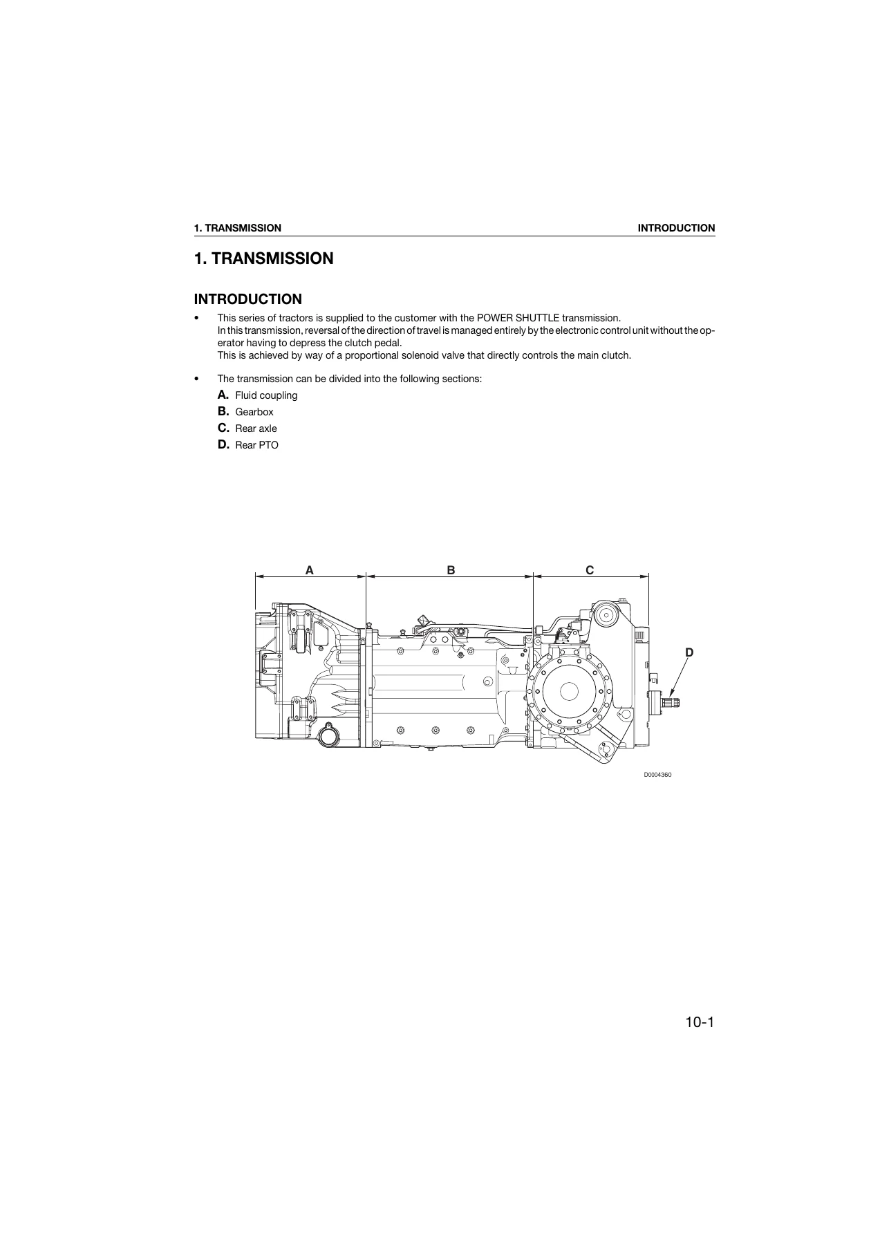
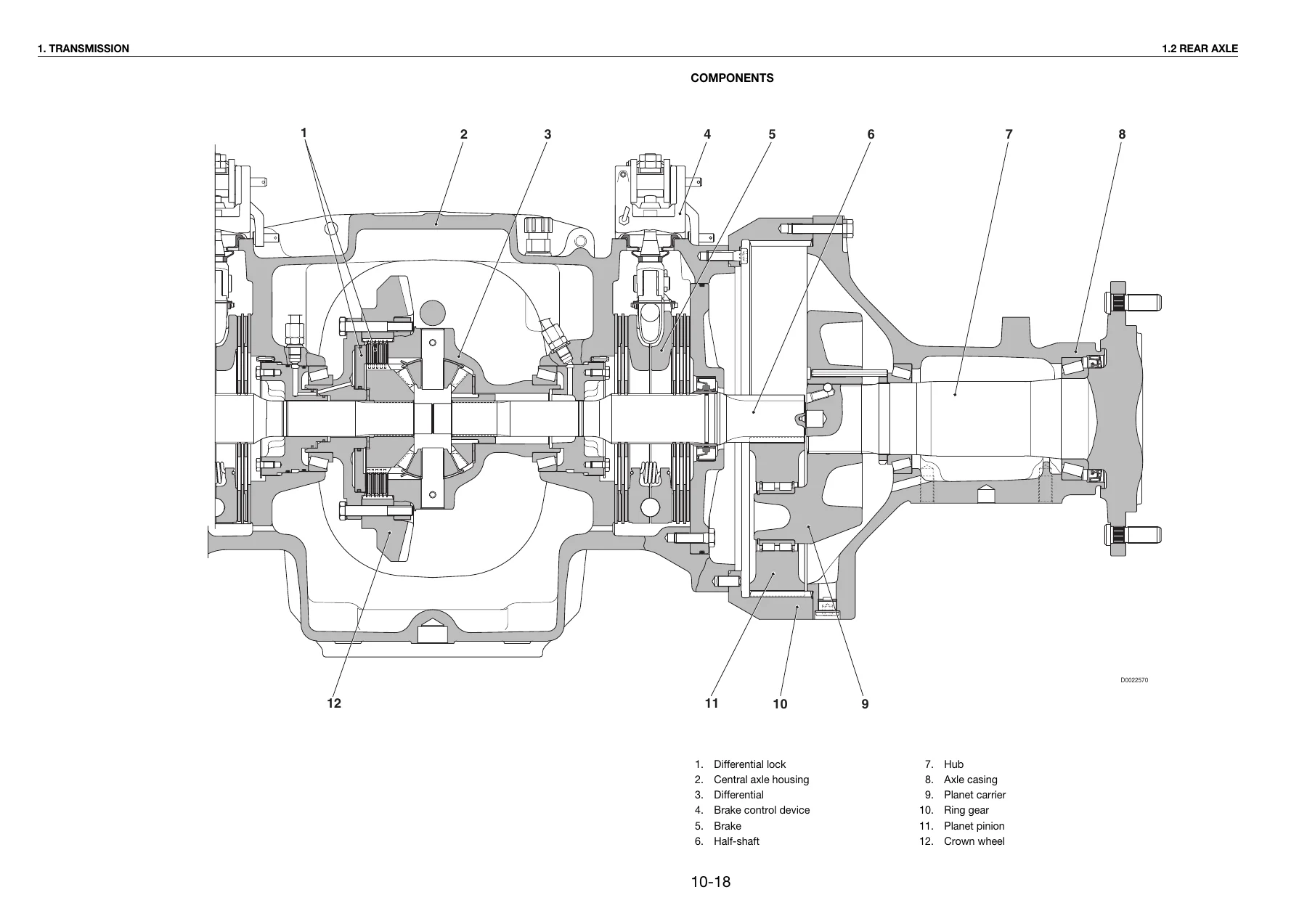
- Section 10 — Transmission and Hydraulics: Power Shuttle transmission introduction, main components, transmission hydraulic system, gearbox description, main clutch operation, hydraulic gearbox and shuttle distribution valve (including gearbox control valve and shuttle control valve), clutch engagement and solenoid valve operation schematic, transmission electronic system schematic, rear axle description and components, rear PTO description, braking system (brake master cylinder, brake, hydraulic trailer braking Italy and Export versions, air trailer braking Italy and Export versions, compressor, pressure limiting valve, cab suspension feed valve, trailer braking valve 2-way and 1-way), hydraulic front axle suspension and control valve, front axle (hub carrier, final reduction unit, differential with 100% hydraulic locking and 45% self-locking versions), hydraulic system (CC version and LS version), variable displacement pump, boost pump, hydraulic pump, load sensing valve, pressure cut-off valve, hydraulic services gear pump, steering gear pump, priority valve, auxiliary services control valve, control valve sections and seals, lift control valve section.
- Section 20 — Electronics and Diagnostics: Diagnosis tools including All Round Tester (ART), SERDIA 3.5 Level III software, EDS EST45 software, connecting the tester to electronic control units, introduction to the tractor electronic system, engine control unit (DEUTZ EMR2), transmission control unit, power lift control unit, ASM system, Infocenter 2 or 3, front axle suspension control unit, front and rear PTO control unit, putting the tractor into service (renewal of engine control unit, transmission control unit, hydraulic lift and ASM control unit, Infocenter, axle suspension control unit), alarms for lift and ASM control unit (extended code, standard code, ART display), transmission control unit alarms, alarms displayed by SERDIA, front axle suspension control valve alarms, operator’s manual for EDS (Electronic Diagnosis System), DEST 45 program, Infocenter diagnosis, All Round Tester for lift and ASM control unit, All Round Tester for axle suspension control unit, and SERDIA Level III operation.
- Section 30 — External Components: Removal and refitting procedures for rigid pipes and wiring, engine hood and lamp assemblies, cab access steps, battery, air reservoir and battery support, starter motor, alternator, air conditioning compressor drivebelt and fanbelt renewal, air compressor, trailer parking and service air brake control valves, pressure transducer, air pressure regulating/reduction valve for cab lifting, trailer air brakes coupling valve, hydraulic trailer braking valve, air conditioning system and components (compressor, receiver-drier, condenser, intercooler, gearbox oil/fuel coolers, radiator, expansion tank, radiators-coolers assembly, fan, front PTO flexible coupling, air cleaner, turbocharger, air inlet pipe, silencer, exhaust pipe), 4WD propeller shaft, brake master cylinders, bleeding the braking system, adjustment of brake light switches, power steering unit and seals, front and rear wheels, front fenders, lift valve block, front lift cylinders, front lift assembly, front PTO assembly, front suspension cylinders, front axle and swinging support, front suspension valves, positioning of front suspension position sensor, reinforcing side members, front carrier, accelerator potentiometer, fuel tank, power steering pump, auxiliary services pumps, gear pump, variable displacement pump, priority valve, creeper engagement lever, control valve assemblies (CC and LS versions), control valve sections and seals, lift cylinders, lift position sensor, lift draft sensor, driver’s seat, controls in multifunction armrest console, steering wheel and column switch unit, centre console and shroud, right-hand console, left-hand console, transmission/lift/front suspension electronic control units, fuse and relay board, engine ECU, clutch pedal and related devices, control panels and levers for auxiliary service valves and PTO, PTO engagement and selection control cables, auxiliary service valve control cables, parking brake switch, climate control panel, heater valve, heater matrix, air conditioning evaporator, air conditioning fans, parking brakes, cab door cable, trailer braking air pressure gauge, Powershift/Powershuttle status display, cab removal, and engine removal.
- Section 40 — Electrical Systems and Wiring: Structure of the unit, how to consult the unit, introduction, list of wiring harnesses, definition of components and symbols, general rules for modifying electrical/electronic circuits, main wiring faults, removal/refitting/drying of connectors and wiring, diagnostic instruments, wire colour codes, component description index, component code index, connector index, connector layouts, component technical data, pinouts and descriptions of electronic control units (engine, transmission, Infocenter, HPSA, front suspension), systems (ground points, engine start, preheating, electrical engine control, lights, cab accessory, working lights, windscreen wiper, Infocenter, electrical power supply, autoradio, air conditioning/heating fan, brakes, trailer brakes, front axle suspension, transmission, ASM/4WD/differential, rear lifter, front and rear PTO), and complete wiring diagrams for engine, engine hood, transmission, trailer brake, front axle suspension, cab power supply, fenders, number plate lights, front console, side console, air conditioning, display, roof, cab lower headlights, windscreen wiper motor, cab lower front worklights, cab full and dipped beam headlights, cab roof front and rear worklights, lights selector switch, armrest, and fuses and relays control unit.
Together, these five sections give you a complete picture of the Agrotron 108 118 128 tractor. Section 00 establishes the safety framework and standard values. Section 10 explains how the major mechanical and hydraulic systems are designed and how they operate, with detailed descriptions of the Power Shuttle transmission, the hydraulic gearbox and shuttle distribution valve, the rear axle and differential, the braking system in all its variants, the front axle suspension, and the full hydraulic system in both CC and LS configurations. Section 20 covers the electronic control units that manage the engine, transmission, lift, ASM, Infocenter, front axle suspension and PTO, together with the diagnostic tools and procedures needed to read alarms, calibrate sensors and put the tractor back into service after component renewal. Section 30 provides step-by-step removal and refitting procedures for external components, from the engine hood and radiator to the front axle, lift assembly, fuel tank and cab. Section 40 delivers the electrical system documentation, including connector layouts, pinouts, component technical data, system diagrams and complete wiring harness diagrams.
What This Manual Does Not Cover
This Agrotron 108 118 128 workshop manual does not contain the engine or transmission sections. For those sections, separate manuals are referenced: the DEUTZ engine manual (20120312 0361, available in Italian, English, French and German), the transmission/rear axle manual (7200 L-S-H, 0298 6831 German, 0298 6832 English, 0298 6833 French, 0298 6834 Spanish), and the front axle manual (ZF 2025-2035-2045 AS, 0298 6803 German, 0298 6856 English, 0298 6857 French, 0298 6858 Spanish).
Who This Manual Is For
This Deutz-Fahr Agrotron 108 118 128 repair manual is written for repair technicians and authorized service centres. It assumes a thorough knowledge of the machine and its components, operation and controls, and it provides the correct methods for fault diagnosis, working in safety, dimensional checks and visual inspections. It also specifies the products to use, the tightening torques and the adjustment data. If you are a technician who works on Agrotron tractors, this manual gives you the information you need to carry out repairs and overhauls correctly.
Why This Workshop Manual Matters
Having the correct procedures and specifications for the Agrotron 108, 118 and 128 is not optional. The Power Shuttle transmission, the hydraulic gearbox and shuttle distribution valve, the front axle suspension, the electronic control units and the braking system all require precise adjustment and calibration. Without the correct tightening torques, dimensional checks and diagnostic procedures, you risk damaging components, causing unsafe operating conditions, or creating faults that are difficult to trace. This Deutz-Fahr Agrotron workshop manual provides the reference data and the step-by-step instructions that allow you to work confidently and correctly.
What You Can Do With This Manual
- Diagnose faults across the transmission, hydraulics, braking system, front axle suspension and electrical/electronic systems using the alarm lists, diagnostic procedures and system schematics.
- Remove and refit major assemblies including the engine hood, radiator, intercooler, front axle, lift assembly, PTO, fuel tank, cab and engine.
- Service and repair the braking system, including hydraulic and air trailer braking variants, brake master cylinders and bleeding procedures.
- Work on the hydraulic system, including the variable displacement pump, gear pump, priority valve, auxiliary services control valve and lift control valve section.
- Carry out electronic calibration and programming using the ART, SERDIA and EDS tools, and put the tractor back into service after renewing control units.
- Trace electrical faults using the connector layouts, pinouts, system diagrams and complete wiring harness diagrams in Section 40.
- Reference tightening torques, conversion factors, sealants, lubricants and threadlockers from Section 00.
Instant PDF Delivery
This Deutz-Fahr Agrotron 108 118 128 tractor workshop manual is delivered as an instant PDF download after payment. There is no shipping, no waiting for a physical book, and no restrictions on where you can use it. You can access it on any device that reads PDFs, print the pages you need for the workshop, and keep the complete manual on hand for every service and repair job. Whether you are working on a single Agrotron 108, a fleet of Agrotron 118 tractors, or a customer’s Agrotron 128, this workshop manual gives you the full technical documentation in a convenient, searchable and printable format.
Stop guessing at procedures and specifications. Get the Deutz-Fahr Agrotron 108 118 128 Workshop Manual PDF and have the complete repair and service information at your fingertips.
Reviews
There are no reviews yet.