★ TRUSTED BY 321,897+ PROFESSIONALS WORLDWIDE
🏢
Trusted Business
Verified & Licensed
🛡️
Virus Free Files
100% Safe Downloads
🔒
Secure Payment
SSL Protected
Instant Delivery
Available Immediately
Sale!

John Deere 1023E 1025R 1026R Compact Utility Tractor Technical Manual TM126919

Original price was: $29.95.Current price is: $17.95.

Complete TM126919 technical repair manual for the John Deere 1023E, 1025R and 1026R compact utility tractors, covering engine, fuel, electrical, power train, hydraulics, and diagnostic testing. Instant PDF download.

SKU: JD-TM126919-HD Category: Tags: , , , Vendor: Brake Service Docs
Instant PDF Download
Available immediately
💾
Save to Your Device
Download & keep forever
🛡️
Antivirus Scanned
100% virus-free
🌍
Trusted Worldwide
175,000+ customers

Description

John Deere 1023E 1025R 1026R Compact Utility Tractor Technical Manual TM126919

This is the complete John Deere 1023E 1025R 1026R Compact Utility Tractor Technical Manual TM126919, published January 2013, written for the experienced technician who repairs and services these compact tractors. Unlike an owner’s manual, this technical manual is the shop-level reference used to diagnose failures, test systems, and carry out the actual repair procedures on the 1023E, 1025R, and 1026R EEC models.

File Details

  • Manual type: Technical (Service/Repair) Manual
  • Brand: John Deere
  • Covered models: 1023E, 1025R, 1026R (1026R EEC)
  • Document number: TM126919
  • Publication date: January 2013
  • Language: English
  • Page count: 1399 pages
  • File format: PDF

Chapters Covered

  • Section 10 – General Information
    • Safety
    • General Specifications
    • Fuel and Lubricants
    • Serial Number Locations
    • Features and Accessories

    IMAGES PREVIEW

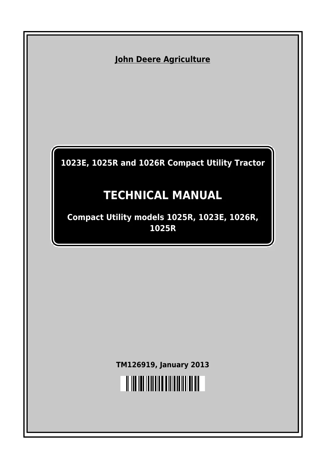
    John Deere 1023E 1025R 1026R Compact Utility Tractor Technical Manual TM126919 — PDF page 1 preview
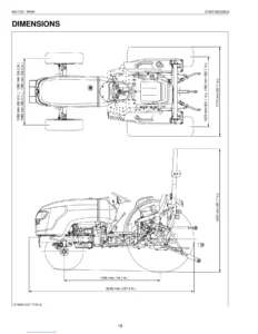
    John Deere 1023E 1025R 1026R Compact Utility Tractor Technical Manual TM126919 — PDF page 43 preview
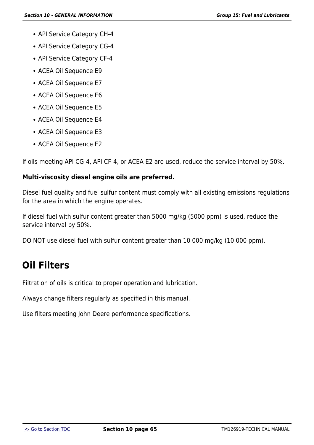
    John Deere 1023E 1025R 1026R Compact Utility Tractor Technical Manual TM126919 — PDF page 71 preview

  • Section 20 – Engine Repair
    • Engine
    • Cooling System
  • Section 30 – Fuel and Air Repair
    • Fuel System
    • Air Intake and Exhaust Systems
    • Speed Control Linkage
  • Section 40 – Electrical Repair
    • Battery, Starter and Alternator
    • Electrical System Components
    • Wiring Harness
  • Section 50 – Power Train Repair
    • Transmission
    • Rear PTO Driveshaft
    • Differential
    • Final Drives
    • Mechanical Front Wheel Drive
  • Section 60 – Steering and Brake Repair
    • Steering Repair
    • Brake Repair
  • Section 70 – Hydraulics Repair
    • Hydraulic Pump and Filter
    • Rockshaft
    • Selective Control Valve
  • Section 80 – Miscellaneous Repair
    • Wheels
    • 3-Point Hitch
    • Hood
    • Mid-Mount Lift
  • Section 90 – Operator’s Station Repair
    • Seat and Support
    • ROLL-GARD
    • Operator Platform
    • Fenders
  • Section 210 – Operational Checkout Procedures
  • Section 220 – Engine Operation, Tests, and Adjustments
    • Component Location
    • Theory of Operation
    • Diagnosis, Tests, and Adjustments
  • Section 230 – Fuel and Air Operation, Tests, and Adjustments
  • Section 240 – Electrical System Operation, Tests, and Adjustments
    • Wiring Schematics
    • Connector Information
  • Section 250 – Power Train Operation, Tests, and Adjustments
  • Section 260 – Steering and Brake Operation, Tests, and Adjustments
  • Section 270 – Hydraulic System Operation, Tests, and Adjustments
    • Hydraulic Tests
    • Adjustments
    • Hydraulic Schematics
  • Section 299 – Service Tools
    • Dealer Fabricated Tools
    • Service Tools and Kits

Complete PDF Bookmark Tree

Complete Bookmarks

The complete bookmarks in the “John Deere 1023E 1025R 1026R Compact Utility Tractor Technical Manual TM126919” are as follows:

Table of contentsp. 2
FOREWORDp. 5
Section 10 – GENERAL INFORMATIONp. 8
Group 05 – Safetyp. 8
Recognize Safety Informationp. 8
Handle Fuel Safely—Avoid Firesp. 8
Prevent Battery Explosionsp. 9
Prepare for Emergenciesp. 10
Prevent Acid Burnsp. 12
Service and Operate Chemical Sprayers Safelyp. 14
Handle Chemical Products Safelyp. 15
Avoid High-Pressure Fluidsp. 17
Park Machine Safelyp. 17
Support Machine Properlyp. 18
Wear Protective Clothingp. 19
Work in Clean Areap. 20
Service Machines Safelyp. 21
Work In Ventilated Areap. 22
Illuminate Work Area Safelyp. 23
Replace Safety Signsp. 24
Use Proper Lifting Equipmentp. 25
Remove Paint Before Welding or Heatingp. 26
Avoid Heating Near Pressurized Fluid Linesp. 27
Keep ROPS Installed Properlyp. 28
Service Tires Safelyp. 29
Avoid Harmful Asbestos Dustp. 31
Practice Safe Maintenancep. 32
Use Proper Toolsp. 34
Dispose of Waste Properlyp. 35
Prevent Machine Runawayp. 36
Handle Starting Fluid Safelyp. 36
Service Cooling System Safelyp. 37
Stay Clear of Rotating Drivelinesp. 39
Protect Against High Pressure Sprayp. 41
Construct Dealer-Made Tools Safelyp. 41
Clean Vehicle of Hazardous Pesticidesp. 42
Servicing Electronic Control Unitsp. 44
Welding Near Electronic Control Unitsp. 45
Keep Electronic Control Unit Connectors Cleanp. 47
Live With Safetyp. 47
Group 10 – General Specificationsp. 49
Machine Specifications 1023E, 1025R, and 1026R EECp. 49
Service Recommendations for O-Ring Boss Fittingsp. 52
Service Recommendations For Flat Face O-Ring Seal Fittingsp. 55
Metric Cap Screw Torque Values—Grade 7p. 57
Metric Bolt and Screw Torque Valuesp. 58
Unified Inch Bolt and Screw Torque Valuesp. 59
Group 15 – Fuel and Lubricantsp. 61
Diesel Fuelp. 61
Handling and Storing Diesel Fuelp. 62
Do Not Use Galvanized Containersp. 63
Lubricity of Diesel Fuelp. 64
Testing Diesel Fuelp. 64
Biodiesel Fuelp. 65
Filling Fuel Tankp. 67
Diesel Engine Break-In Oilp. 69
Diesel Engine Oilp. 70
Oil Filtersp. 71
Heavy Duty Diesel Engine Coolantp. 72
Operating in Warm Temperature Climatesp. 73
Additional Information About Diesel Engine Coolants and John Deere LIQUID COOLANT CONDITIONERp. 74
Testing Diesel Engine Coolantp. 76
Transmission and Hydraulic Oilp. 77
Use Correct Transmission/Hydraulic Filter Elementp. 78
MFWD Axle Housing and Wheel Hub Oilp. 79
Greasep. 80
Grease (Specific Application)p. 82
Mixing of Lubricantsp. 82
Alternative and Synthetic Lubricantsp. 82
Lubricant Storagep. 83
Group 20 – Serial Number Locationsp. 84
Serial Numbersp. 84
Product Identification Number Locationp. 84
Engine Serial Number Locationp. 84
Group 25 – Features and Accessoriesp. 86
Features and Accessoriesp. 86
Section 20 – ENGINE REPAIRp. 89
Group 05 – Enginep. 89
Summary of Referencesp. 89
Specificationsp. 91
Other Materialp. 100
Service Equipment and Toolsp. 100
Essential or Recommended Toolsp. 101
Remove Enginep. 102
Install Enginep. 112
Remove and Install Valve Coverp. 123
Remove and Install Rocker Arm Assembly and Push Rodsp. 125
Disassemble, Inspect, and Assemble Rocker Arm Assembly and Push Rodsp. 126
Remove and Install Exhaust Manifoldp. 131
Remove and Install Cylinder Headp. 133
Disassemble and Assemble Cylinder Headp. 137
Recondition Cylinder Headp. 140
Replace Crankshaft Rear Oil Seal: 3TNM74p. 159
Replace Crankshaft Rear Oil Seal: 3TNV76 and 3TNV80p. 160
Remove and Install Crankshaft Rear Oil Seal Case: 3TNV76 and 3TNV80p. 162
Replace Crankshaft Front Oil Sealp. 164
Remove and Install Timing Gear Coverp. 167
Remove, Inspect, and Install Idler Gearp. 171
Remove, Inspect, and Install Camshaft Followersp. 177
Remove and Install Camshaftp. 180
Inspect Camshaft, Gear, Bushing and Boresp. 184
Remove and Install Oil Pan and Strainer: 3TNM74p. 194
Remove and Install Oil Pan and Strainer: 3TNV76 and 3TNV80p. 197
Check Connecting Rod Side Playp. 200
Check Crankshaft End Playp. 202
Check Connecting Rod Bearing Clearancep. 204
Check Crankshaft Main Bearing Clearancep. 207
Remove Piston and Connecting Rodp. 211
Install Piston and Connecting Rodp. 212
Disassemble and Inspect Piston and Connecting Rodp. 216
Assemble Piston and Connecting Rodp. 228
Inspect Cylinder Borep. 234
Rebore Cylinderp. 239
Remove Crankshaft and Main Bearings: 3TNM74p. 243
Install Crankshaft and Main Bearings: 3TNM74p. 244
Remove Crankshaft and Main Bearings: 3TNV76 and 3TNV80p. 254
Install Crankshaft and Main Bearings: 3TNV76 and 3TNV80p. 256
Remove and Install Flywheelp. 259
Remove and Install Engine Back Platep. 260
Inspect Oil Pump: 3TNM74p. 262
Inspect Oil Pump: 3TNV76 and 3TNV80p. 268
Group 10 – Cooling Systemp. 275
Summary of Referencesp. 275
Specificationsp. 276
Remove and Install Fan and Alternator Beltp. 277
Remove and Install Radiatorp. 279
Remove and Install Water Pumpp. 285
Remove and Install Thermostatp. 296
Remove and Install Coolant Temperature Sensorp. 301
Install Block Heater: 3TNM74p. 305
Install Block Heater: 3TNV76 and 3TNV80p. 312
Section 30 – FUEL AND AIR REPAIRp. 319
Group 05 – Fuel Systemp. 319
Summary of Referencesp. 319
Specificationsp. 320
Other Materialp. 320
Service Equipment and Toolsp. 320
Bleed Fuel Systemp. 321
Remove and Install Fuel Transfer Pumpp. 323
Remove and Install Fuel Injection Nozzlep. 325
Clean and Inspect Fuel Injection Nozzlep. 330
Remove Fuel Injection Pump: 3TNM74p. 334
Install Fuel Injection Pump: 3TNM74p. 340
Remove Fuel Injection Pump: 3TNV76 and 3TNV80p. 344
Install Fuel Injection Pump: 3TNV76 and 3TNV80p. 350
Remove and Install Fuel Shutoff Solenoidp. 352
Remove and Install Fuel Filter Assemblyp. 354
Disassemble and Assemble Fuel Filter and Water Separatorp. 356
Remove and Install Inline Fuel Filterp. 360
Group 10 – Air Intake and Exhaust Systemsp. 362
Summary of Referencesp. 362
Remove and Install Mufflerp. 363
Group 15 – Speed Control Linkagep. 366
Summary of Referencesp. 366
Replace Throttle Cablep. 367
Section 40 – ELECTRICAL REPAIRp. 371
Group 05 – Battery, Starter and Alternatorp. 371
Summary of Referencesp. 371
Specificationsp. 372
Essential or Recommended Toolsp. 372
Remove and Install Batteryp. 373
Remove and Install Starting Motorp. 376
Remove and Install Alternatorp. 379
Disassemble and Inspect Alternatorp. 381
Assemble Alternatorp. 393
Group 10 – Electrical System Componentsp. 404
Summary of Referencesp. 404
Electrical System Componentsp. 405
Electrical Components – EECp. 407
Group 15 – Wiring Harnessp. 409
Summary of Referencesp. 409
1023E Wiring Harnessp. 409
1025R Wiring Harnessp. 413
1026R EEC Wiring Harnessp. 417
Section 50 – POWER TRAIN REPAIRp. 424
Group 15 – Transmissionp. 424
Summary of Referencesp. 424
Specificationsp. 425
Other Materialp. 425
Remove Transmissionp. 426
Install Transmissionp. 441
Remove and Install Hydrostatic Drivep. 457
Disassemble and Inspect Hydrostatic Drivep. 460
Assemble Hydrostatic Drivep. 469
Remove and Install Range Transmissionp. 477
Group 20 – Rear PTO Driveshaftp. 487
Summary of Referencesp. 487
Specificationsp. 488
Other Materialp. 488
Essential or Recommended Toolsp. 489
Remove PTO Clutchp. 490
Disassemble and Inspect PTO Clutchp. 496
Assemble PTO Clutchp. 501
Install PTO Clutchp. 507
Remove and Inspect Rear PTO Driveshaft and Gearsp. 515
Install Rear PTO Driveshaft and Gearsp. 525
Remove and Inspect Mid PTO Driveshaft and Gearsp. 528
Install Mid PTO Driveshaft and Gearsp. 541
Group 25 – Differentialp. 559
Summary of Referencesp. 559
Specificationsp. 559
Other Materialp. 559
Remove and Install Differentialp. 560
Disassemble and Inspect Differentialp. 567
Assemble Differentialp. 575
Group 30 – Final Drivesp. 578
Summary of Referencesp. 578
Essential or Recommended Toolsp. 578
Remove and Install Rear Axlep. 579
Group 35 – Mechanical Front Wheel Drivep. 593
Summary of Referencesp. 593
Specificationsp. 593
Remove Front Axlep. 594
Install Front Axlep. 597
Disassemble Front Axlep. 601
Assemble Front Axlep. 613
Disassemble Front Outer Axlep. 620
Assemble Front Outer Axlep. 634
Disassemble MFWD Differentialp. 646
Assemble MFWD Differentialp. 650
Section 60 – STEERING AND BRAKE REPAIRp. 655
Group 05 – Steering Repairp. 655
Summary of Referencesp. 655
Specificationsp. 656
Remove and Install Steering Wheelp. 656
Remove and Install Steering Cylinderp. 658
Remove and Install Tilt Steering Assemblyp. 660
Disassemble Tilt Steering Assemblyp. 663
Assemble Tilt Steering Assemblyp. 672
Remove Steering Control Unit (SCU)p. 681
Install Steering Control Unit (SCU)p. 683
Remove and Install Tie Rodp. 684
Group 10 – Brake Repairp. 686
Summary of Referencesp. 686
Specificationsp. 686
Other Materialp. 686
Disassemble and Inspect Brakesp. 687
Assemble Brakesp. 691
Section 70 – HYDRAULICS REPAIRp. 698
Group 05 – Hydraulic Pump and Filterp. 698
Summary of Referencesp. 698
Specificationsp. 698
Remove and Install Hydraulic Pumpp. 699
Disassemble and Inspect Hydraulic Pumpp. 703
Assemble Hydraulic Pumpp. 711
Remove and Install Oil Suction Screenp. 715
Remove PTO Valvep. 722
Install PTO Valvep. 724
Group 10 – Rockshaftp. 726
Summary of Referencesp. 726
Specificationsp. 727
Other Materialp. 727
Remove Rockshaft Housingp. 728
Install Rockshaft Housingp. 732
Disassemble Rockshaftp. 740
Assemble Rockshaftp. 748
1025R Disassemble Rockshaft Position Feedbackp. 759
1025R Assemble Rockshaft Position Feedbackp. 764
Group 15 – Selective Control Valvep. 771
Summary of Referencesp. 771
Specificationsp. 771
Remove and Install Selective Control Valve (SCV)p. 772
Inspect Selective Control Valve (SCV)p. 775
Section 80 – MISCELLANEOUS REPAIRp. 780
Group 10 – Wheelsp. 780
Summary of Referencesp. 780
Specificationsp. 780
Remove and Install Front Wheelsp. 781
Remove and Install Rear Wheelsp. 781
Group 15 – 3-Point Hitchp. 783
Summary of Referencesp. 783
Adjust 3-Point Hitchp. 784
Remove and Install 3-Point Hitchp. 787
Group 20 – Hoodp. 790
Summary of Referencesp. 790
Remove and Install Hoodp. 791
Group 25 – Mid-Mount Liftp. 794
Summary of Referencesp. 794
Specificationsp. 795
Remove Mid Mount Mower Draft Armp. 796
Install Mid Mount Mower Draft Armp. 798
Remove Mid Mount Rockshaft and Lift Armp. 802
Install Mid Mount Rockshaft and Lift Armp. 809
Install Mid Mount Lift Actuator, Mechanicalp. 818
Install Mid Mount Lift Actuator, Hydraulicp. 824
Remove Mid Mount Mower Lift Hydraulic Hose and Cylinderp. 831
Install Mid Mount Mower Lift Hydraulic Cylinder and Hosep. 838
Adjust Mid Mount Lift – Mechanical Liftp. 850
Section 90 – OPERATOR′S STATION REPAIRp. 855
Group 05 – Seat and Supportp. 855
Summary of Referencesp. 855
Specificationsp. 855
Remove Seatp. 855
Install Seatp. 857
Remove Seat Basep. 860
Install Seat Basep. 863
Group 10 – ROLL-GARDp. 866
Summary of Referencesp. 866
Specificationsp. 866
Remove ROPSp. 867
Install ROPSp. 871
Group 15 – Operator Platformp. 875
Summary of Referencesp. 875
Specificationsp. 875
Remove Control Panelp. 876
Install Control Panelp. 885
Remove and Install Center Closeout Panelp. 892
Group 20 – Fendersp. 894
Summary of Referencesp. 894
Remove Right Fenderp. 895
Install Right Fenderp. 900
Remove Left Fender and Fuel Tankp. 904
Install Left Fender and Fuel Tankp. 909
Section 210 – OPERATIONAL CHECKOUT PROCEDURESp. 915
Group 05 – Operational Checkout Proceduresp. 915
Summary of Referencesp. 915
Referencep. 916
Preliminary Checksp. 916
Referencep. 918
Perform Rear Differential Lock Operational Checkp. 918
Referencep. 919
PTO Indicator Light Checkp. 919
PTO Operational Checkp. 919
Referencep. 921
RIO Operational Checkp. 921
Referencep. 923
PTO Switch Checkp. 923
Seat Switch Interface Checkp. 923
Referencep. 925
Rear Brake Operational Checkp. 925
Referencep. 925
Preliminary Checkp. 926
Referencep. 927
Operational Checkp. 927
Referencep. 929
Basic Hydraulic Function Checksp. 929
Section 220 – ENGINE OPERATION, TESTS, AND ADJUSTMENTSp. 932
Group 05 – Component Locationp. 932
Summary of Referencesp. 932
3TNM74 Engine Component Locationsp. 932
3TNV76 and 3TNV80 Engine Component Locationsp. 933
Group 10 – Theory of Operationp. 934
Summary of Referencesp. 934
Cooling System Theory of Operationp. 935
Lubrication System Theory of Operationp. 937
Group 15 – Diagnosis, Tests, and Adjustmentsp. 939
Summary of Referencesp. 939
Specificationsp. 940
Other Materialp. 940
Service Equipment and Toolsp. 940
Essential or Recommended Toolsp. 942
Adjust Throttle Cablep. 943
Adjust Slow Idlep. 945
Adjust Fast Idlep. 947
Adjust Valve Clearancep. 948
Check Camshaft End Playp. 956
Check Timing Gear Backlashp. 958
Cylinder Compression Test—3TNM74p. 961
Cylinder Compression Test—3TNV76 and 3TNV80p. 964
Pressure Test Cooling Systemp. 967
Test Thermostatp. 969
Pressure Test Radiator Capp. 972
Test Oil Pressurep. 974
Adjust Fan and Alternator Beltp. 976
Section 230 – FUEL AND AIR OPERATION, TESTS, AND ADJUSTMENTSp. 980
Group 05 – Component Locationp. 980
Summary of Referencesp. 980
Fuel Systemp. 980
Group 10 – Theory of Operationp. 981
Summary of Referencesp. 981
Air Intake System Theory of Operationp. 982
Fuel System Theory of Operationp. 983
Group 15 – Diagnosis, Test and Adjustmentsp. 985
Summary of Referencesp. 985
Specificationsp. 986
Other Materialp. 986
Service Equipment and Toolsp. 986
Essential or Recommended Toolsp. 988
Test Fuel Injection Systemp. 989
Test Fuel Injection Nozzlep. 992
Injection Pump Timing (EPA Engines)p. 996
Check Injection Pump Static Timingp. 997
Adjust Fuel Injection Timing: 3TNM74p. 1005
Adjust Fuel Injection Timing: 3TNV76 and 3TNV80p. 1009
Test Fuel Supply Pressure and Flowp. 1011
Test Air Filter Restriction Indicatorp. 1013
Section 240 – ELECTRICAL SYSTEM OPERATION, TESTS, AND ADJUSTMENTSp. 1020
Group 05 – Component Locationp. 1020
Summary of Referencesp. 1020
Electrical Componentsp. 1021
Electrical Components – EECp. 1023
Load Center – Domesticp. 1024
Load Center – EECp. 1027
Group 10 – Theory of Operationp. 1029
Summary of Referencesp. 1029
Charging Circuit – 1023Ep. 1030
Cranking and Starting Circuit – 1023Ep. 1032
Instrument Control Cluster (ICC) – 1023Ep. 1036
Power Circuit – 1023Ep. 1041
PTO Circuit – 1023Ep. 1045
Lighting Circuit – 1023Ep. 1048
Charging Circuit – 1025Rp. 1052
Cranking and Starting Circuit – 1025Rp. 1054
Instrument Control Cluster (ICC) – 1025Rp. 1058
Power Circuit – 1025Rp. 1063
PTO Circuit – 1025Rp. 1067
Lighting Circuit – 1025Rp. 1070
Group 15 – Diagnosis, Test and Adjustmentsp. 1074
Summary of Referencesp. 1074
Specificationsp. 1075
Service Equipment and Toolsp. 1075
Essential or Recommended Toolsp. 1075
Power Circuit Diagnosis 1023E and 1025Rp. 1076
Charge Circuit Diagnosis 1023E and 1025Rp. 1079
Crank Circuit Diagnosis 1023E and 1025Rp. 1080
Fuel Shutoff Circuit Diagnosis 1023E and 1025Rp. 1082
Glow Plug Circuit Diagnosis 1023E and 1025Rp. 1084
PTO Circuit Diagnosis 1023E and 1025Rp. 1085
Lighting Circuit Diagnosis 1023Ep. 1087
Lighting Circuit Diagnosis 1025Rp. 1089
Instrument Control Cluster (ICC) Diagnosisp. 1091
Key Switch Testp. 1093
PTO Switch Testp. 1095
Park Brake Switch Testp. 1097
Reverse Pedal Switch Testp. 1099
Reverse Pedal Switch Adjustmentp. 1101
Seat Switch Testp. 1105
Light Switch Testp. 1107
Turn Signal Switch Testp. 1109
Hazard Switch Testp. 1110
PTO MBR Switch Testp. 1112
PTO Solenoid Testp. 1114
Neutral Switch Testp. 1117
Horn Switch Testp. 1119
Relay Testp. 1120
Oil Pressure Switch Testp. 1123
Coolant Temperature Sensor Testp. 1125
Fuel Shutoff Solenoid Testp. 1127
Regulated Voltage Output Testp. 1129
Group 20 – Wiring Schematicsp. 1130
Summary of Referencesp. 1130
Schematic Informationp. 1130
1023E Schematic Legendp. 1131
1023E Schematicp. 1133
1025R Schematic Legendp. 1141
1025R Schematicp. 1143
1026R EEC Schematic Legendp. 1151
1026R EEC Schematicp. 1153
Group 25 – Connector Informationp. 1163
Summary of Referencesp. 1163
K01— K04 Relay Connectorp. 1165
K05— K06 Relay Connectorp. 1167
X03 Power Port Connectorp. 1169
X09 Mow Lift Solenoid Connectorp. 1171
X54 RH Fender Light Connectorp. 1173
X55 LH Fender Light Connectorp. 1175
X—E01 and X—E02 Headlight Connectorp. 1177
X—E01 and X—E02 EEC Headlight Connectorp. 1179
X—G02 Alternator Connectorp. 1181
X—ICC—J1 Display Connectorp. 1183
X—ICC—J1 Display EEC Connectorp. 1185
X—ICC—J2 Display Connectorp. 1187
X—ICC—J2 Display EEC Connectorp. 1189
X—ICC—J3 Display Connectorp. 1191
X—K07 Flasher Connectorp. 1193
X—M01 Start Motor Connectorp. 1195
X—M02 Fuel Pump Connectorp. 1197
X—R01 Glow Plug Connectorp. 1199
X—S01 Key Switch Connectorp. 1201
X—S02 (X—S08 EEC) Light Switch Connectorp. 1203
X—S03 Turn Signal Switch Connectorp. 1205
X—S04 Neutral Start Switch Connectorp. 1207
X—S05 (X—S02 EEC) PTO Switch Connectorp. 1209
X—S08 (X—X07) MBR Switch Connectorp. 1210
X—S10 Mow Lift Switch Connectorp. 1212
X—S13 Hazard Switch Connectorp. 1214
X—S38 Seat Switch Connectorp. 1216
X—S40 Front Hitch Detection Connectorp. 1218
X—S41 Park Brake Switch Connectorp. 1220
X—S41 Park Brake Switch Connector — EECp. 1222
X—S42 Brake Switch Connectorp. 1224
X—S60 Reverse Pedal Sense Connectorp. 1226
X—Y02 Fuel Shutoff Solenoid Connectorp. 1228
X—Y03 PTO Solenoid Connectorp. 1230
Section 250 – POWER TRAIN OPERATION, TESTS, AND ADJUSTMENTSp. 1233
Group 05 – Component Locationp. 1233
Summary of Referencesp. 1233
Transmission Sub-Assembliesp. 1233
Driveshaftp. 1234
Hydraulic Transmissionp. 1237
Gear Transmission Sub-Assembliesp. 1238
Transmission Housingp. 1240
Range Gears, Pinion, and Bevel Gearp. 1242
Differentialp. 1243
Brakesp. 1245
Axlesp. 1246
Mechanical Front Wheel Drive (MFWD)p. 1247
PTO Clutchp. 1249
PTO Drivep. 1251
Rockshaft – 1023Ep. 1253
Rockshaft With Feedback – 1025Rp. 1255
Hydraulic Pump and PTO Valvep. 1258
Front Axle Input Gear and Differentialp. 1260
Front Axle Case and Tie Rodp. 1261
Front Axle Final Drive Gearsp. 1264
Group 10 – Theory of Operationp. 1266
Summary of Referencesp. 1266
Gear Train Operationp. 1267
Range Gear Operationp. 1269
MFWD Operationp. 1271
PTO Operationp. 1273
Group 15 – Diagnosis, Test and Adjustmentsp. 1277
Summary of Referencesp. 1277
Specificationsp. 1278
Essential or Recommended Toolsp. 1278
MFWD Diagnosisp. 1280
Adjust Neutral Creepp. 1281
Adjust Differential Lockp. 1286
Adjust Forward and Reverse Pedalsp. 1288
Cone Point and Backlash Settingp. 1297
Section 260 – STEERING AND BRAKE OPERATION, TESTS, AND ADJUSTMENTSp. 1316
Group 05 – Component Locationp. 1316
Summary of Referencesp. 1316
Steering Componentsp. 1316
Tilt Steering Componentsp. 1317
Brake Componentsp. 1318
Park Brake Components – Exportp. 1319
Group 10 – Theory of Operationp. 1321
Summary of Referencesp. 1321
Steering System Operationp. 1322
Group 15 – Diagnosis, Test and Adjustmentsp. 1323
Summary of Referencesp. 1323
Specificationsp. 1323
Adjust Brakesp. 1324
Adjust Park Brake Engagementp. 1331
Adjust Park Brake Engagement EECp. 1334
Check Toe-inp. 1336
Section 270 – HYDRAULIC SYSTEM OPERATION, TESTS, AND ADJUSTMENTSp. 1340
Group 05 – Component Locationp. 1340
Summary of Referencesp. 1340
Hydraulic Pumpp. 1340
PTO Solenoidp. 1343
Group 10 – Theory of Operationp. 1345
Summary of Referencesp. 1345
Surge Relief Valve Operationp. 1346
Group 15 – Diagnosisp. 1348
Summary of Referencesp. 1348
Diagnostic Informationp. 1349
Preliminary Hydraulic System Inspectionp. 1350
Entire Hydraulic System Fails to Function/No Hydraulic Pump Outputp. 1351
Insufficient Pump Deliveryp. 1352
Hydraulic Functions Too Slowp. 1353
Excessive Pump Pressurep. 1354
Slow Hydraulic Pump Responsep. 1355
Excessive Pump Noise During Operationp. 1356
Rockshaft Does Not Lift or Lifts Slowlyp. 1357
Rockshaft Does Not Lower or Lowers Slowlyp. 1358
Neutral Position Unstable, Rockshaft Drops after Engine Shut Downp. 1359
Mid-Mount Joystick Does Not Return to Neutral Position—Mid-Mount SCVp. 1360
Mid-Mount Joystick Does Not Remain in Detent Position—Mid-Mount SCVp. 1361
Remote Cylinder Does Not Extend or Retractp. 1362
Remote Cylinder Settles Under Loadp. 1363
Remote Cylinder Operates Too Fast or Too Slowp. 1364
Group 20 – Hydraulic Testsp. 1365
Summary of Referencesp. 1365
Specificationsp. 1366
Essential or Recommended Toolsp. 1367
Hydraulic Oil Warm-up Procedurep. 1367
Test SCV Implement Relief Pressurep. 1368
Test PTO Cluch Pressurep. 1370
Test HST Charge Pressurep. 1372
Check Rate of Drop/Stop Valvep. 1374
Referencep. 1376
Install Test Equipmentp. 1376
Pump Flow Test (With SCV)p. 1376
Referencep. 1378
Install Test Equipmentp. 1378
Main Relief Valve Test (With SCV)p. 1378
Referencep. 1380
Install Test Equipmentp. 1380
Perform SCV Leakage Testp. 1380
Referencep. 1382
Perform Lift Cycle Testp. 1382
Referencep. 1384
Test Conditionsp. 1384
Open Rate of Drop Testp. 1384
Closed Rate of Drop Testp. 1386
Group 25 – Adjustmentsp. 1388
Summary of Referencesp. 1388
Specificationsp. 1388
Adjust Rockshaft Position Feedbackp. 1389
Adjust Rockshaft Feedback Friction Washersp. 1390
Group 30 – Hydraulic Schematicsp. 1391
Summary of Referencesp. 1391
Hydraulic Circuit Symbolsp. 1391
1023E Hydraulic Schematicp. 1393
1025R Hydraulic Schematicp. 1394
Section 299 – SERVICE TOOLSp. 1398
Group 05 – Dealer Fabricated Toolsp. 1398
Summary of Referencesp. 1398
PTO Clutch Spring Compression Toolp. 1398
Group 10 – Service Tools and Kitsp. 1399
Essential or Recommended Toolsp. 1399

Across nearly 1,400 pages, this John Deere 1023E 1025R 1026R technical manual gives a technician everything needed to move from symptom to fix: component locations, theory of operation for each major system, step-by-step diagnostic testing, adjustment specifications, and full teardown/rebuild procedures for the engine, power train, hydraulics, steering, brakes, and electrical system.

Machine Coverage

The manual documents all three EEC variants side by side: the 1023E with its Yanmar 3TNM74 diesel engine, the 1025R with the Yanmar 3TNV80, and the 1026R EEC with the Yanmar 3TNV76 — each an in-line 3-cylinder, liquid-cooled diesel with indirect injection and a mechanical rotary injection pump. It covers the hydrostatic transmission and 2-range gear final drive, fully independent 540 rpm PTO, hydrostatic power steering, internal wet-disk brakes, and the open-center gear-pump hydraulic system shared across the model line, along with fluid capacities, torque specifications, and metric and inch fastener torque charts used throughout every repair procedure in the book.

Get the Most Out of This Manual

With this John Deere 1023E 1025R 1026R Technical Manual TM126919, you can diagnose engine, fuel, electrical, power train, steering, brake, and hydraulic faults using the same theory-of-operation and diagnostic testing sequences John Deere technicians rely on, then follow the documented procedures to correctly torque fasteners, service the fuel and lubrication systems, and rebuild or replace components on the 1023E, 1025R, and 1026R. Working from the correct specifications and procedures protects the machine from improper repairs and helps avoid comebacks. This is an instant PDF download — there’s no shipping wait, it opens on a computer, tablet, or phone, and you can print any page you need right in the shop.
Reviews

There are no reviews yet.

Be the first to review “John Deere 1023E 1025R 1026R Compact Utility Tractor Technical Manual TM126919”

What Our Customers Say

★★★★★ Live reviews from customers
Loading customer reviews...
0
    0
    Your Cart
    Your cart is emptyReturn to Shop
    🛒
    Recently Purchased
    🕒 verified order