
Doosan B10R-5 B13R-5 B15R-5 B16R-5 Electric Forklift Service Manual – SB4292E
Original price was: $39.95.$24.95Current price is: $24.95.
Complete Doosan SB4292E service manual bundle for the B10R-5, B13R-5, B15R-5 and B16R-5 electric forklifts – AC MicroController control system, power train, vehicle systems, mast, hydraulic and electric schematics, alarm code diagnostics and the full Operation & Maintenance Manual. 494-page PDF.
Description
Doosan B10R-5, B13R-5, B15R-5 and B16R-5 Electric Forklift Service Manual
The Doosan B10R-5 B13R-5 B15R-5 B16R-5 Electric Forklift Service Manual is the full SB4292E service documentation set for the 24 V AC counterbalance trucks in the B16R-5 family. It is not a single thin booklet – the bundle gathers every sub-manual listed on the SB4293E00 contents form, so one PDF carries the safety rules, the general torque charts, the AC MicroController control system module, the power train module, two vehicle system modules, the mast module, both schematics and the Operation & Maintenance Manual. Anyone servicing a B10R-5, B13R-5, B15R-5 or B16R-5 gets wiring references, hydraulic circuits, alarm codes and disassembly sequences that belong to these four machines rather than a generic electric truck.
File Details
- Manual type: Multi-module service manual bundle (service, disassembly and assembly, schematics, operation and maintenance)
- Brand / manufacturer: DOOSAN
- Models covered: B10R-5, B13R-5, B15R-5, B16R-5
- Power type: Battery electric, 24 V, AC inverter drive
- Language: English
- File format: PDF
- Page count: 494 pages
- Master contents form: SB4293E00
- Bundle form number: SB4292E
- Sub-manual form numbers: SB2003E01 (Safety), SB2004E00 (Torque Specifications), SB4294E00 (MicroController Control Systems), SB4295E01 (Power Train), SB4296E00 and SB4297E00 (Vehicle System), SB4298E00 (Mast System), SB4299E00 (Hydraulic Schematic), SB4300E01 (Electric Schematic), SB2351E (Operation & Maintenance Manual)
- Dates shown: Feb. 2013, July 2007, May 2008 (per module)
Chapters Covered
- Safety – warning plates and decals, protective clothing, blocking and jack stands, battery isolation and capacitor discharge, hydraulic pressure release, welding precautions, asbestos handling guidelines
- Torque Specifications – metric nuts and bolts, metric taperlock studs, inch nuts and bolts, inch taperlock studs, straight thread O-ring fittings, O-ring face seal fittings, 37 degree flared and straight thread O-ring fittings, 45 degree flared and inverted flare fittings, Hi Duty shear sleeve, Hi Seal, Ermeto and Flex fittings, hose clamp band type, hydraulic line installation
- MicroController Control Systems – specifications, systems operation, glossary, installation and wiring, preparation tests and check, programmable parameters, some functions management, general description, alarm list, troubleshooting problem list, system tests and adjustments, electrical system adjustment, instrument panel, display keys utilization, parameter calibration, sensor initial setting, default setting, diagnostic mode, accessing stored error codes, EYE software interface, Appendix A parameter list, Appendix B error code list, Appendix C dot matrix contractions
- Power Train – AC drive motor, thermal sensor tests, sensor bearing, wheel mounting, motor and transfer, brake, hydraulic brake system connection, brake cable connection, transmission fluid replenishment, front axle, drive axle GK25LD (A473022), drive axle GK26LD (101587-00013), troubleshooting, disassembly and assembly
- Vehicle System – hydraulic control valve and spool positions, relief valve, hydraulic pump, sideshift cylinder, standard and full free lift cylinders, tilt cylinder, steering wheel, priority valve, steering hydraulic motor, steering gear, hydraulic pump motor, brake master cylinder, testing and adjusting
- Vehicle System Disassembly & Assembly – hood with seat, overhead guard, hydraulic control valve, hydraulic pump motor, hydraulic pump, accelerator control switch, standard, secondary and primary lift cylinders, tilt cylinder, steer sensor group, steering wheel and column, steering gear, priority valve, brake master cylinder, steer wheel, transfer and drive motor, control panel, drive axle, counterweight
- Mast System – forks, backrest, carriage, mast removal and installation, mast disassembly and assembly, chain adjustments, chain wear test, carriage and mast height adjustment, forks parallel check, tilt cylinder alignment, drift test, tilt cylinder adjustment, lift and tilt mounting group adjustment, mast mounting group adjustment
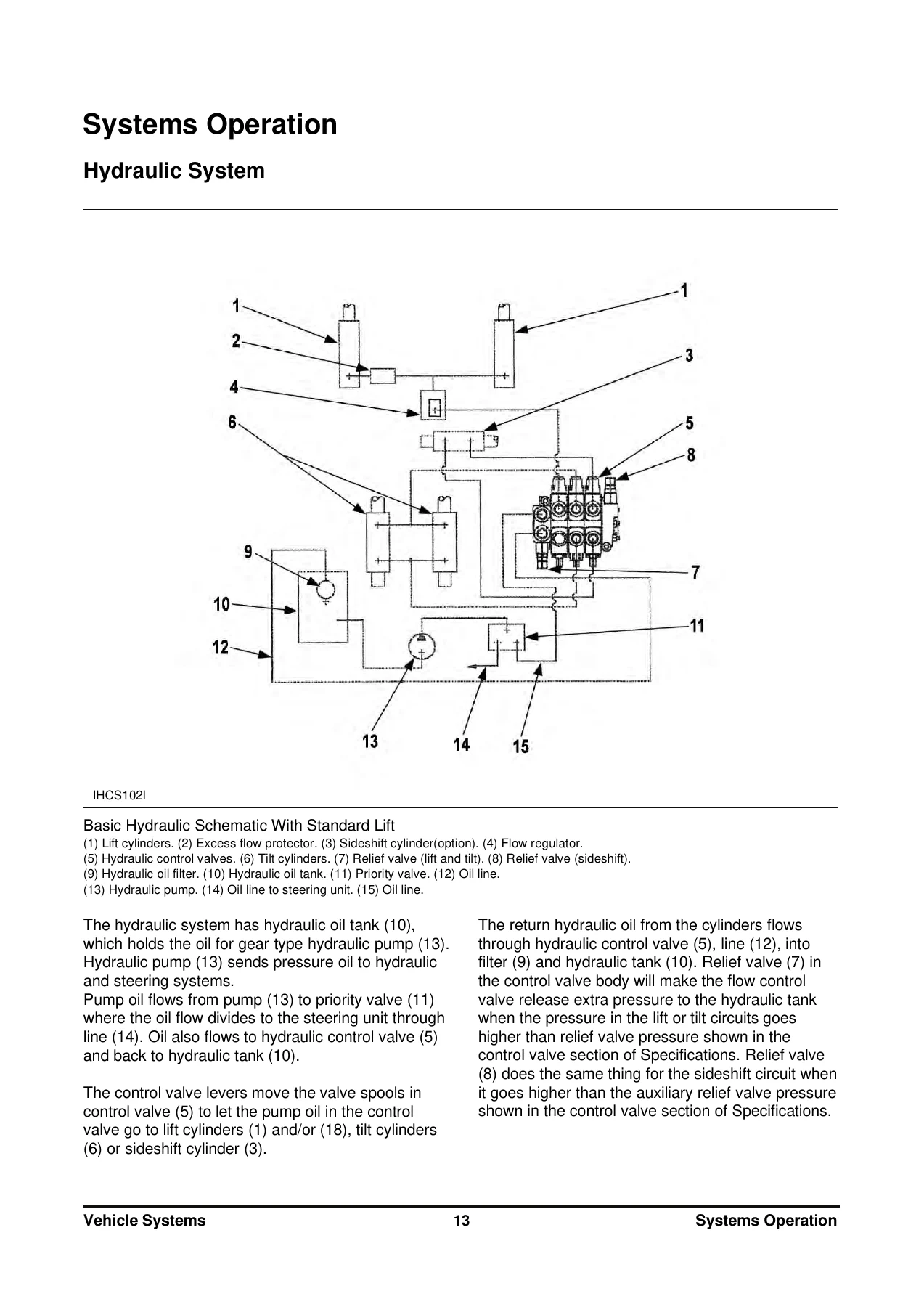
- Hydraulic Schematic – main and auxiliary relief valve pressures, full circuit diagram for the B10/13/15/16R-5
- Electric Schematic – AC 24 V wiring schematic and option light schematic
- Operation & Maintenance Manual – foreword, safety, warning signs and labels, general hazard information, lift chains, operation information, maintenance information, operator restraint system, avoiding lift truck tipover, safety rules, how to survive in a tipover, declaration of conformity, specifications, noise and vibration, capacity chart, serial number, operator warning and identification plate, operator station and monitoring systems, lift truck controls, before operating, lift truck operation, operating techniques, parking, lift fork adjustment, storage, transportation, towing, fork inspection, tire inflation, torque specifications, lubricant specifications, battery discharge indicator, battery, cold storage applications, lubricant viscosities and refill capacities, maintenance intervals, environment protection
Read together, these modules take a technician from the general (safety rules and the universal torque charts that apply across the truck) to the specific (the inverter parameters that decide how a B16R-5 accelerates, the shim thickness that sets drive axle bearing preload, the exact bleed sequence for a wet disc brake). The MicroController module supplies the electrical brain of the truck, the Power Train and Vehicle System modules supply the mechanical and hydraulic muscle, and the Mast System module supplies the lifting structure and its alignment procedures. The schematics tie it all together so a circuit or a hose can be traced end to end instead of guessed at.
Inside the AC MicroController Control System Module
This is the largest and most technically dense part of the Doosan B10R-5 B13R-5 B15R-5 B16R-5 service manual. It documents a 24 V controller rated for 12-32 V battery voltage with a maximum impulsive drive inverter current of 600 A and the same figure for the pump inverter, a 3-6-9 kHz switching frequency, 95 percent efficiency, IP65 protection, mechanical size of 382 x 220 x 123 mm, 6.5 kg weight, 5g vibration resistance from 10-500 Hz on the X, Y and Z axes, an operating temperature range of -30 degrees C to +40 degrees C, a maximum module temperature of 100 degrees C, a 600 A main contactor, a 700 A main fuse and a 10 A key fuse.
Motor data is given for both units. The drive motor is listed as 24 V, 5 kW, 16 V, 240 A, 1866 rpm rated speed, 4500 rpm maximum speed, 65 Hz, cos phi 0.874, insulation class F, IP 22 protection, 6208 2RS bearings and 32 kg. The pump motor is listed as 24 V, 7 kW, 16 V, 335 A, 1550 rpm rated speed, 4500 rpm maximum speed, 55 Hz, cos phi 0.902, insulation class F, IP 22 protection, 6208 2RS bearings and 32 kg.
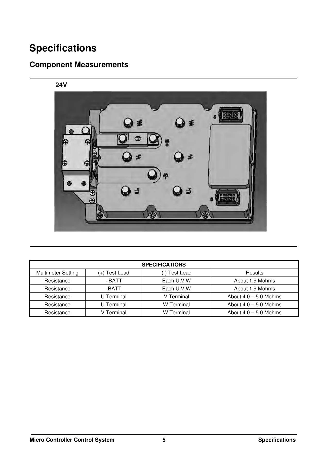
- Component measurements and multimeter resistance values across the +BATT, -BATT, U, V and W terminals
- Controller AS specification, fuse ratings and panel layout
- Assembly layout of the controller and of the drive and pump motors
- The actuation circuit, power steering circuit, lift control circuit, thermal protection circuits and accessory circuits
- Thermal thresholds – power module warning at 100 degrees C, drive and pump motor stator sensors warning at 155 degrees C
- Programmable parameter tables covering acceleration, inversion, release and pedal brake ramps, forward and reverse maximum speed, drive limitation speed, creep speed, drive tire diameter, lift and auxiliary speeds, hydro speed, hydro idle speed, timers, battery reset value and E-S-H energetic modes
- Diagnostic mode parameter list and stored error code retrieval
Alarm Codes and Diagnostic Troubleshooting
The troubleshooting chapter is organised around the alarm levels the controller reports, and each entry gives the eye alarm code, the display code, the alarm level, the cause and a step-by-step remedy. The problem list includes maximum and minimum battery voltage, pedal trimmer fault, EEPROM alarm, pre-charge capacitor conditions, drive and pump module overcurrent, module and motor overtemperature, low battery, motor current offset, main breaker fault, watchdog timer, serial communication, 5 V and 12 V encoder supply faults, pump command active on start, battery mismatch, encoder faults and thermal sensor mismatch. A separate troubleshooting problem list walks through display codes E1, E3, E4, E6, EL, EE, F, F0 through F9, FA, Fc, FH, FL, A, 60, 61, 65, 76, 77, 79, 80, 82, 83 and 84, each with a possible cause and a check sequence. Appendix C converts those codes into the contractions the dot matrix display actually shows, so CONTACTOR FAULT, BATT MISMATCH, R-MOTOR SHUTDOWN, P-MOTOR ENCODER, R-INV OVERTEMP and similar messages can be read directly off the panel.
Power Train, Front Axle and Drive Axle
The power train module documents the drive motor, transfer, brake and front axle as a system. It includes a thermal switch warning temperature of 155 plus or minus 4 degrees C, drive wheel mounting nut torque of 190 N.m plus or minus 10 N.m (140 plus or minus 7 lb.ft), housing-to-mast bolt torque of 300 N.m plus or minus 30 N.m (222 plus or minus 22 lb.ft), transfer and drive motor socket head bolt torque of 23 N.m plus or minus 5 N.m (17 plus or minus 4 lb.ft), transfer-to-frame bolt torque of 80 N.m plus or minus 5 N.m (59 plus or minus 4 lb.ft), and bleeder port, brake line and brake cable torques of 50 N.m plus or minus 5 N.m (37 plus or minus 4 lb.ft) each. Front axle oil is specified as MOBIL #424 with a 0.5 L quantity, the service brake as an oil disc brake, the brake oil as AZOLLA-ZS10 and the parking brake as a lever revolution type. Two drive axle variants are covered in full disassembly and assembly detail: GK25LD (A473022) and GK26LD (101587-00013), including bearing preload measurement, shim selection, contact pattern checking, torsional backlash between 0.03 and 0.11 mm, and rolling torque values.
Hydraulic, Mast and Brake Service
The vehicle system module covers the control valve in neutral, lift, lower, tilt neutral, tilt forward and tilt back positions, plus relief valve operation, the steering unit and steering gear, the priority valve, the master cylinder and the wet disc brake. Main relief valve pressure is 15,900 kPa (2,306 psi) for the B10/13R-5 and 17,500 kPa (2,538 psi) for the B15/16R-5, with auxiliary relief at 14,000 kPa (2,040 psi) and a steering priority relief setting of roughly 10,340 to 10,840 kPa (1,500 to 1,570 psi). The hydraulic pump is a gear type with 16 cc/rev displacement. The mast module adds chain adjustment, a chain wear test with a two percent replacement limit, carriage and mast height measurements, fork parallelism tolerances, tilt cylinder alignment and a drift test with a ten minute limit of 100.0 mm (4.00 in).
Schematics and Maintenance Intervals
Both schematics are included in full: the hydraulic schematic for the B10/13/15/16R-5 and the AC 24 V electric wiring schematic with the option light schematic. The Operation & Maintenance Manual section supplies the lubricant viscosities and refill capacities, lubricant specifications, battery care and charging rules, cold storage guidance, and the complete maintenance interval schedule from every 10 service hours or daily through every 2,500 service hours or 15 months.
Why This Doosan Service Manual Is Worth Having
A 24 V AC electric forklift is not a machine you troubleshoot by ear. The inverter decides how the truck behaves, the alarm codes tell you which subsystem has stepped out of range, and the mechanical work – bearing preload, shim thickness, chain tension, brake bleeding – has to be done to a number. The Doosan B10R-5 B13R-5 B15R-5 B16R-5 Electric Forklift Service Manual gives you those numbers in one place: the inverter parameters and diagnostic codes, the torque tables for both metric and inch hardware, the hydraulic pressures, the axle adjustment values, the mast tolerances and the scheduled maintenance intervals. Whether you are chasing an E4 drive motor overtemperature alarm, resealing a tilt cylinder, resetting the EEPROM after a control board change, or simply running the 1,000-hour service, the procedure and the specification are both here.
IMAGES PREVIEW
Delivery is instant. The manual is supplied as a downloadable PDF – no shipping, no waiting, no physical book to lose in the workshop. Open it on a laptop, tablet or phone at the machine, print the pages you need for the job, and keep the rest of the 494-page Doosan SB4292E bundle on hand for the next repair.
Reviews
There are no reviews yet.