
TCM FGE15-35E2 & FD20-35E2 Series Forklift Service Manual – STFEE-CH18E-202 PDF
Original price was: $44.95.$25.95Current price is: $25.95.
Complete TCM counter-balanced forklift service manual for the FGE15E2 through FGE35E2 LPG trucks and FD20E2 through FD35E2 diesel trucks. 16 chapters covering controllers, powershift transmission, hydraulics, mast and forks, axles, brakes, steering and full circuit diagrams. Document STFEE-CH18E-202, published August 2021.
Description
TCM FGE15-35E2 & FD20-35E2 Series Forklift Service Manual
This is the full service manual for TCM counter-balanced forklift trucks in the FGE15E2 through FGE35E2 LPG range and the FD20E2 through FD35E2 diesel range. It is the workshop reference that covers the truck as a whole system, from the GK21E/GK25E LPG and D04EG diesel engine mountings down to the final drive, mast rollers and brake shoes. If you are working on any of these chassis codes, this is the document that carries the procedures, clearances, tightening torques and wiring you will actually use on the shop floor.
File Details
- Manual type: Service Manual (Workshop Manual)
- Brand: TCM
- Manufacturer: Mitsubishi Logisnext Europe B.V. (MLE)
- Document number: STFEE-CH18E-202
- Publication date: August 2021 (originally issued 31 August 2021)
- Language: English
- File format: PDF
- Contents: 16 chapters, including full circuit diagrams
- Engines covered: GK21E / GK25E LPG, D04EG diesel
- Transmission type: Powershift (torque converter) and MC/FC hydraulic control variants
Trucks Covered by the TCM FGE15-35E2 & FD20-35E2 Forklift Service Manual
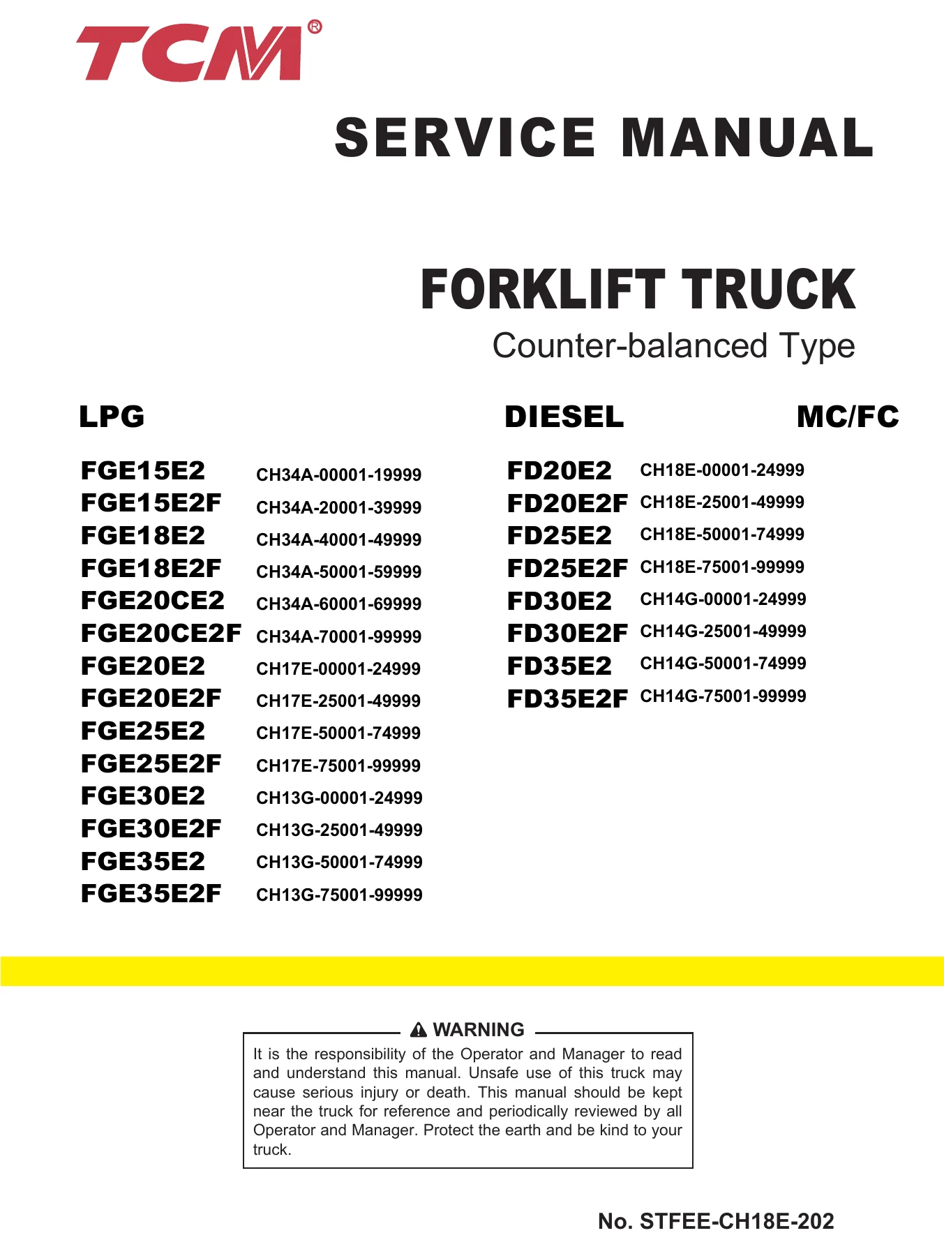
The manual identifies each truck by model name and serial number range, which is how TCM separates running changes across the FGE and FD lines. The LPG trucks are grouped by chassis prefix CH34A, CH17E and CH13G. The diesel trucks use CH18E and CH14G. Both MC (mechanical control) and FC (finger-tip control) truck types are covered, and the FC type is used on torque converter models only.
- FGE15E2 – CH34A-00001 to 19999, GK21E LPG
- FGE15E2F – CH34A-20001 to 39999, GK21E LPG
- FGE18E2 – CH34A-40001 to 49999, GK21E LPG
- FGE18E2F – CH34A-50001 to 59999, GK21E LPG
- FGE20CE2 – CH34A-60001 to 69999, GK21E LPG (compact, short wheelbase)
- FGE20CE2F – CH34A-70001 to 99999, GK21E LPG
- FGE20E2 – CH17E-00001 to 24999, GK21E LPG
- FGE20E2F – CH17E-25001 to 49999, GK21E LPG
- FGE25E2 – CH17E-50001 to 74999, GK21E LPG
- FGE25E2F – CH17E-75001 to 99999, GK21E LPG
- FGE30E2 – CH13G-00001 to 24999, GK25E LPG
- FGE30E2F – CH13G-25001 to 49999, GK25E LPG
- FGE35E2 – CH13G-50001 to 74999, GK25E LPG
- FGE35E2F – CH13G-75001 to 99999, GK25E LPG
- FD20E2 – CH18E-00001 to 24999, D04EG diesel
- FD20E2F – CH18E-25001 to 49999, D04EG diesel
- FD25E2 – CH18E-50001 to 74999, D04EG diesel
- FD25E2F – CH18E-75001 to 99999, D04EG diesel
- FD30E2 – CH14G-00001 to 24999, D04EG diesel
- FD30E2F – CH14G-25001 to 49999, D04EG diesel
- FD35E2 – CH14G-50001 to 74999, D04EG diesel
- FD35E2F – CH14G-75001 to 99999, D04EG diesel
Chapters Covered in This TCM Forklift Service Manual
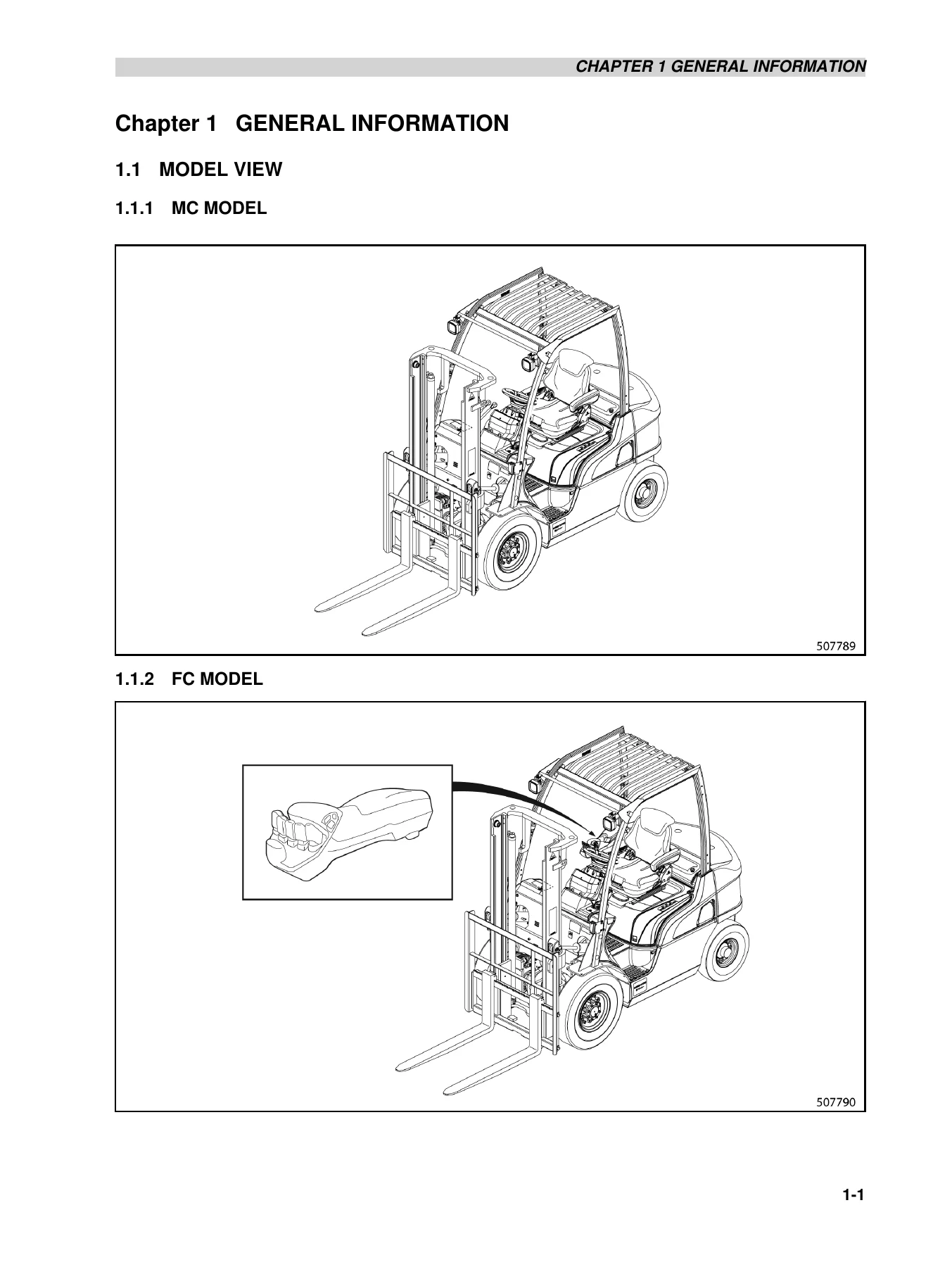
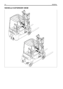
- Chapter 1 – General: Model view (MC and FC), truck nomenclature and definitions, serial number locations, dimensions, technical data, performance
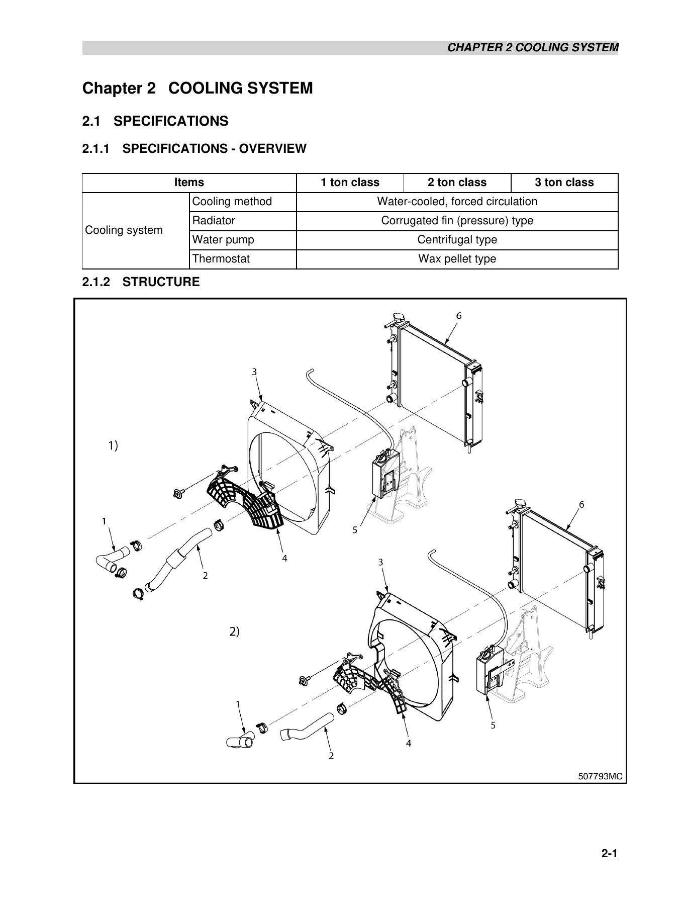
- Chapter 2 – Cooling System: Specifications and structure, fan belt removal/installation, inspection and adjustment, fan belt tension, connecting hoses, unit layout, coolant, radiator cap
- Chapter 3 – Electrical System: Chassis electrical components and wiring outline, console box, main electrical components (meter panel, key switch, combination switch, direction switch, horn, tank unit, brake fluid sensor, stop light switch, thermoswitches, fuse box, relay box, USB port socket), battery maintenance, meter panel operation, wire colour codes, troubleshooting
- Chapter 4 – Controllers: Main functions of VCM, ECM, meter panel, remote I/O units, GSE connector, mast interlock system, driving interlock system, seat belt warning icon, parking brake warning buzzer and icon, harness codes, truck status display and troubleshooting, F-code diagnosis table, LED blink patterns
- Chapter 5 – Power Train: Removal and installation of engine and transmission assembly for MC models (LPG and diesel), removal and installation for FC models, DPF installation, diesel cooling circuit air bleeding
- Chapter 6 – Powershift Transmission: Structure and functions, torque converter, control system, hydraulic schematic, removal and installation, disassembly and assembly of transmission housing, input/idler/output shafts, forward and reverse input shaft gear assemblies, oil pump, control valve (regulator, accumulator, inching valve sections), oil pressure measurement, brake (inching) pedal adjustment, inching cable adjustment, troubleshooting, service data
- Chapter 7 – Front Axle and Reduction Differential: Structure for 1, 2 and 3 ton classes, removal and installation, front wheels, disassembly and assembly of front axle and reduction differential, adjustment of tooth contact, troubleshooting, service data
- Chapter 8 – Rear Axle: Structure and functions, steering cylinder, removal and installation of rear wheel and rear axle assembly, disassembly and assembly of wheel hub, knuckle (king pin), steering cylinder and tie rod
- Chapter 9 – Brake System: Brake system structure, disassembly and assembly of master cylinder, wheel brakes and wheel cylinder, inspection and adjustment (automatic adjuster test, manual adjustment, parking brake cable adjustment, brake pedal adjustment, brake lines bleeding, braking performance test, parking brake lever), troubleshooting, service data
- Chapter 10 – Steering System: Structure and functions, steering valve, steering column, disassembly and assembly of hydraulic components and piping, steering wheel and steering valve, tilt lock lever, steering valve disassembly and assembly order, troubleshooting, service data
- Chapter 11 – Hydraulic System: Structure and functions, hydraulic circuit diagrams (MC and FC), hydraulic tank, hydraulic pump, control valve, flow regulator valve, down safety valve, lift cylinder, tilt cylinder, disassembly and reassembly, inspection and adjustment, MC control valve and FC control valve, service data
- Chapter 12 – Mast and Forks: Simplex mast, duplex mast and triplex mast – overview, mast system, structure and functions, removal order, key points for removal/installation, disassembly order, inspection procedures, lift bracket roller assembly and clearance adjustment, mast roller installation, mast strip installation, lift cylinder installation, chain connection, hydraulic line installation, removal/installation of mast rollers without removing the mast, inspection and adjustment, troubleshooting, service data
- Chapter 13 – Cabin (Option): Cabin model exterior, door opening/closing, removal and installation (front window and wiper, rear window, rear wiper, sleeve tilt cylinder, side door, roof and floor), cabin model labels, switches and controls, heater, AC 12 volt output plug, washer tank, USB port socket, cabin maintenance, USB port plug
- Chapter 14 – Service Data: Maintenance schedule (prestart, weekly, 1st month, 500/1000/1500/2000/3000 hour intervals, 2-year items), maintenance notes for each system, tightening torque for standard bolts and nuts, periodic replacement parts, lubrication instructions and chart, fuel and lubricant specifications, adjustment values and oil quantities, refill capacities, truck weights, dimensions and performance, special service tools
- Chapter 15 – How to Read Circuit Diagrams: Description of circuit diagrams, symbols, sheet symbols, connecting lines, equipment numbering, relay contactor and coil, connectors, indication of GND, alternate specification, how to read connector diagrams, abbreviations
- Chapter 16 – Circuit Diagram: Full circuit diagrams for the D04EG engine model and the GK21/25E engine model (MC and FC), including VCM and ECM sheets
What This TCM FGE15-35E2 / FD20-35E2 Workshop Manual Gives You
A single source that covers the whole truck rather than just the engine or just the mast. The manual is organised by system, so you can jump straight to the section that matches the job in front of you, and each section carries its own specifications and tightening torques rather than pushing you into a separate spec book. The chapters on the controllers, the powershift transmission and the FC control valve are especially deep – these are the areas where generic forklift literature usually falls short and where the TCM truck rewards the technician who has the real data.
For the electrical side, the document goes beyond a simple wiring map. The controller chapter lists the F-code diagnostic table, LED blink patterns, harness codes with pin allocations for the VCM and ECM connectors, and the interlock logic for the mast and driving systems. That means a fault on the seat switch, the parking brake switch or a T/M solenoid can be traced methodically instead of by substitution.
On the mechanical side, the powershift transmission chapter takes you through the torque converter, the oil pump, the forward and reverse input shaft gear assemblies and the control valve down to individual springs, shims and snaprings, with the pressure values needed to confirm the rebuild afterwards. The mast chapter covers simplex, duplex and triplex masts as separate sections, including the roller clearance tables, the chain elongation limits, and the shim sizes used to bring each clearance back into specification.
The service data chapter is the one that will be open most often. It carries the maintenance schedule by hour interval, the refill capacities, the tightening torques for standard bolts and the periodic replacement parts table, so a scheduled service can be planned and priced without guesswork.
Practical Uses for This TCM FGE15E2 to FGE35E2 & FD20E2 to FD35E2 Service Manual
- Diagnose F-code and diagnostic-code faults on the VCM, ECM and meter panel
- Adjust mast and lift bracket roller clearances and shim stacks
- Set chain tension and measure chain elongation against the service limit
- Rebuild the powershift transmission control valve and set main, clutch, torque converter inlet and lubrication pressures
- Adjust the inching pedal and inching cable so the clutch disengages without slipping or burning
- Rebuild the reduction differential and reset the tooth contact pattern
- Service the master cylinder, wheel cylinders and wheel brakes, and adjust the automatic adjuster
- Rebuild the steering valve and set the steering system relief pressure
- Service the hydraulic pump, control valve, lift cylinders and tilt cylinders
- Plan scheduled maintenance using the hour-interval tables and refill capacities
- Trace circuits using the full D04EG and GK21/25E circuit diagrams
Having the correct clearances, torque figures and pressure values in front of you is what keeps a rebuild inside specification. Working from memory or from a generic guide on a truck with a controller-managed mast interlock and an electronically governed powershift transmission is how components get damaged. The TCM FGE15-35E2 and FD20-35E2 service manual removes that risk for every truck listed in the coverage table above.
The file is delivered as an instant PDF download after payment. There is nothing to ship and nothing to wait for. Open it on a workshop laptop, a tablet on the machine, or print the section you need for the job and take it under the truck with you.
Reviews
There are no reviews yet.