★ TRUSTED BY 321,897+ PROFESSIONALS WORLDWIDE
🏒
Trusted Business
Verified & Licensed
πŸ›‘οΈ
Virus Free Files
100% Safe Downloads
πŸ”’
Secure Payment
SSL Protected
⚑
Instant Delivery
Available Immediately
Sale!

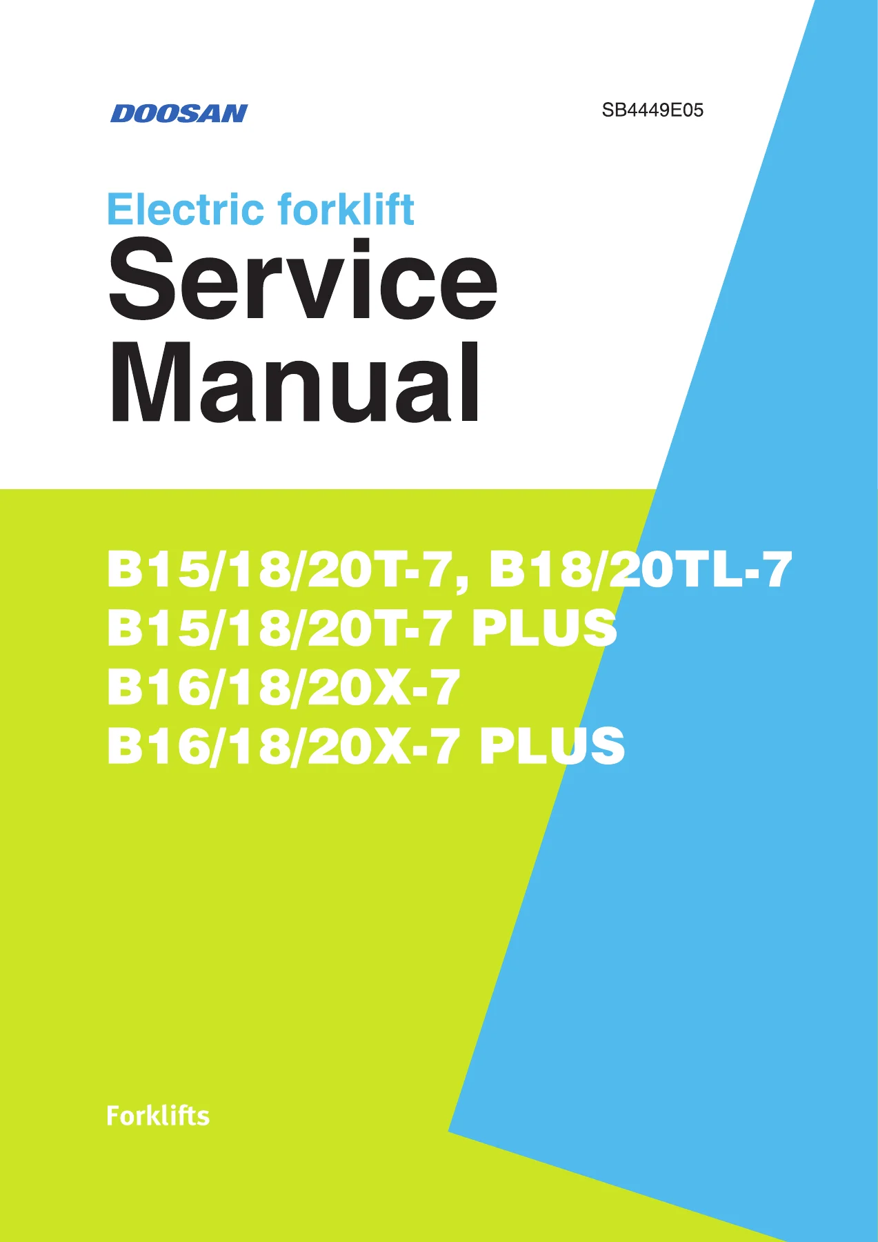
Doosan B15/18/20T-7, B18/20TL-7, B16/18/20X-7 PLUS Electric Forklift Service Manual – SB4449E05

Original price was: $42.95.Current price is: $25.95.

Complete Doosan 7-series electric forklift service manual SB4449E05 covering B15/18/20T-7, B18/20TL-7, B16/18/20X-7 and PLUS models – electrical, drive/brake, hydraulic, lift/tilt, steering, frame, fingertip option and full schematics in one PDF.

⚑
Instant PDF Download
Available immediately
πŸ’Ύ
Save to Your Device
Download & keep forever
πŸ›‘οΈ
Antivirus Scanned
100% virus-free
🌍
Trusted Worldwide
175,000+ customers

Description

The Doosan B15/18/20T-7, B18/20TL-7, B16/18/20X-7 PLUS Electric Forklift Service Manual – SB4449E05 is the full workshop reference for Doosan’s 7-series AC electric counterbalance trucks. It covers the T-series chassis (B15T-7, B18T-7, B20T-7), the long-wheelbase TL variants (B18TL-7, B20TL-7), the compact X-series (B16X-7, B18X-7, B20X-7) and every PLUS derivative of those platforms. Systems are split into nine numbered chapters, each written as a stand-alone service section with illustrations, circuit diagrams, exploded views, torque data and step-by-step disassembly and assembly procedures.

File Details

  • Manual type: Service Manual (workshop / repair)
  • Brand: Doosan – Doosan Industrial Vehicle Co., Ltd.
  • Document number: SB4449E05
  • Covered models: B15T-7, B18T-7, B20T-7, B18TL-7, B20TL-7, B15T-7 PLUS, B18T-7 PLUS, B20T-7 PLUS, B16X-7, B18X-7, B20X-7, B16X-7 PLUS, B18X-7 PLUS, B20X-7 PLUS
  • Language: English
  • Page count: 559
  • File format: PDF
  • Publication date: November 2017, with later revisions reflected in the revision history

Chapters Covered

  • 1 – General: how to use the manual, warning label definitions, glossary, exterior views and specifications for each model group, safety precautions, maintenance intervals, lubricants and capacities, greasing points, disassembly/assembly instructions, standard torques for bolts, nuts and fittings
  • 2 – Electrical System: component overview, CAN communication protocol, battery exterior/specifications, functions, wiring, test, maintenance, removal and installation; controllers and related devices; fuse box, DC-DC converter, lamp group, OSS controller, horn, optional speed limit; instrument panel display, buttons, diagnosis and calibration; EasyView application installation, controller firmware update, administration and tools menus, test menu, calibration menu, initial settings; handling faults on instrument panel and EasyView
  • 3 – Drive/Brake System: drive motor exterior and operation, motor/axle/EM brake removal and installation, motor disassembly, assembly and test, drive wheel removal; drive axle specifications, driving and braking function, drive axle oil replacement, adjustment, disassembly and assembly; accelerator; F/R unit; service brake pedal assembly, brake pedal adjustment, air removal in brake oil, master cylinder disassembly and assembly; Electric Foot Brake (EFB) specifications, operation, pedal removal and adjustment; EM parking brake, parking brake test, manual release of braking; driving, service brake and EM parking brake troubleshooting
  • 4 – Hydraulic System: components and oil flow, pump motor exterior and operation, pump motor and main hydraulic pump removal and installation, pump motor disassembly, assembly and test, main hydraulic pump construction and servicing, priority valve operation, disassembly and assembly, hydraulic tank and filter, hydraulic oil and filter replacement, troubleshooting
  • 5 – Lift/Tilt/Aux System: control valve sections (inlet, lift, tilt, auxiliary, outlet, valve control board), relief valve adjustment, needle valve for emergent lowering, lever and switch group adjustment, control valve removal, disassembly and assembly; STD/FFL/FFT mast construction and lift operation; forks, sideshifter, chains, tilt cylinder, primary lift cylinder, standard/secondary lift cylinder, carriage and mast service; Quad mast primary and standard cylinder service; GSS and auto-tilt leveling options including height switch, mast tilt/auto-tilt switch and hydraulic block assembly; troubleshooting
  • 6 – Steering System: components and oil flow, steering control group exterior and operation, steering system air removal and pressure check, steering wheel cover, steering wheel and column removal, steering unit disassembly and assembly; steering operation group for B15/18/20T (TL) including steer angle sensor, rear wheel and hub adjustment, steer axle spindle and housing assembly; steering operation group for B16/18/20X including steer axle, link assembly, steering knuckle, king pin, bearings and steering cylinder; troubleshooting
  • 7 – Frame: hood, overhead guard, floor plates, top cover and counterweight removal and installation, modular cabin types A, B and C with cabin electric schematic, heater exterior, specifications, operating conditions and modes, maintenance information and troubleshooting
  • 8 – Fingertip Option: overview and circuit, fingertip extension module, fingertip armrest unit wiring, hydraulic control knobs, forward/reverse switch, removal, disassembly and assembly; Kayaba control valve (to July 2018) and Walvoil control valve (July 2018 onward) including relief valve adjustments and manual lowering; steering pressure switch assembly and pump motor operation at steering; fault diagnosis and troubleshooting
  • 9 – Schematics: hydraulic schematic, hydraulic schematic for fingertip with Kayaba valve, hydraulic schematic for fingertip with Walvoil valve, electrical schematic for master cylinder brake models and electrical schematic for Electric Foot Brake models

Taken as a whole, this Doosan electric forklift service manual gives a technician the complete service picture for the 7-series platform rather than a single isolated subsystem. Electrical diagnostics, controller calibration and CAN fault handling sit alongside mechanical teardown of the drive axle, the hydraulic control valve and every mast configuration, so a fault that starts as an error code on the instrument panel can be traced all the way through to the component that caused it. The model-specific specification tables at the front let you confirm capacities, pressures, torques and adjustment limits for the exact truck in front of you before any fastener is loosened.

What You Can Do With This Manual

Because the manual separates the vehicle into its real systems, it supports both scheduled service and full repair work on Doosan B15/18/20T-7, B18/20TL-7, B16/18/20X-7 and PLUS electric forklifts. Typical jobs the procedures directly cover include replacing a drive motor, axle or EM brake; rebuilding a drive axle including carrier, ring gear, drive shaft and wet disc brake assemblies; servicing the master cylinder or the Electric Foot Brake sensor and pedal adjustment; tearing down and resealing the main hydraulic pump and priority valve; adjusting main, tilt-forward and secondary relief pressures; rebuilding tilt, primary, standard, secondary and Quad mast cylinders; chain wear and tension measurement; carriage roller and mast roller shimming; steering unit, steer axle and steering cylinder overhaul; and diagnosing controller, encoder, thermal sensor, CAN, solenoid and fingertip faults through the instrument panel or the EasyView software.

Specifications and Procedures That Keep the Truck Right

Electric forklifts are unforgiving of guessed values. The manual supplies the reference figures that decide whether a repair is correct: drive motor and pump motor ratings, encoder pulse counts, thermal sensor resistance, controller operating limits and current draw, line contactor coil resistance, brake and hydraulic pressures, chain wear percentages, drift limits for tilt and lift cylinders, rolling torque for the drive axle, cylinder rod extension limits and the standard torque tables for metric and inch fasteners and for every fitting type used on the truck. It also documents the initial setting procedures for the accelerator, lift sensor, steering angle sensor and brake pedal, which must be re-performed whenever those components or the controller firmware change.

Illustrations, Diagrams and Fault Coverage

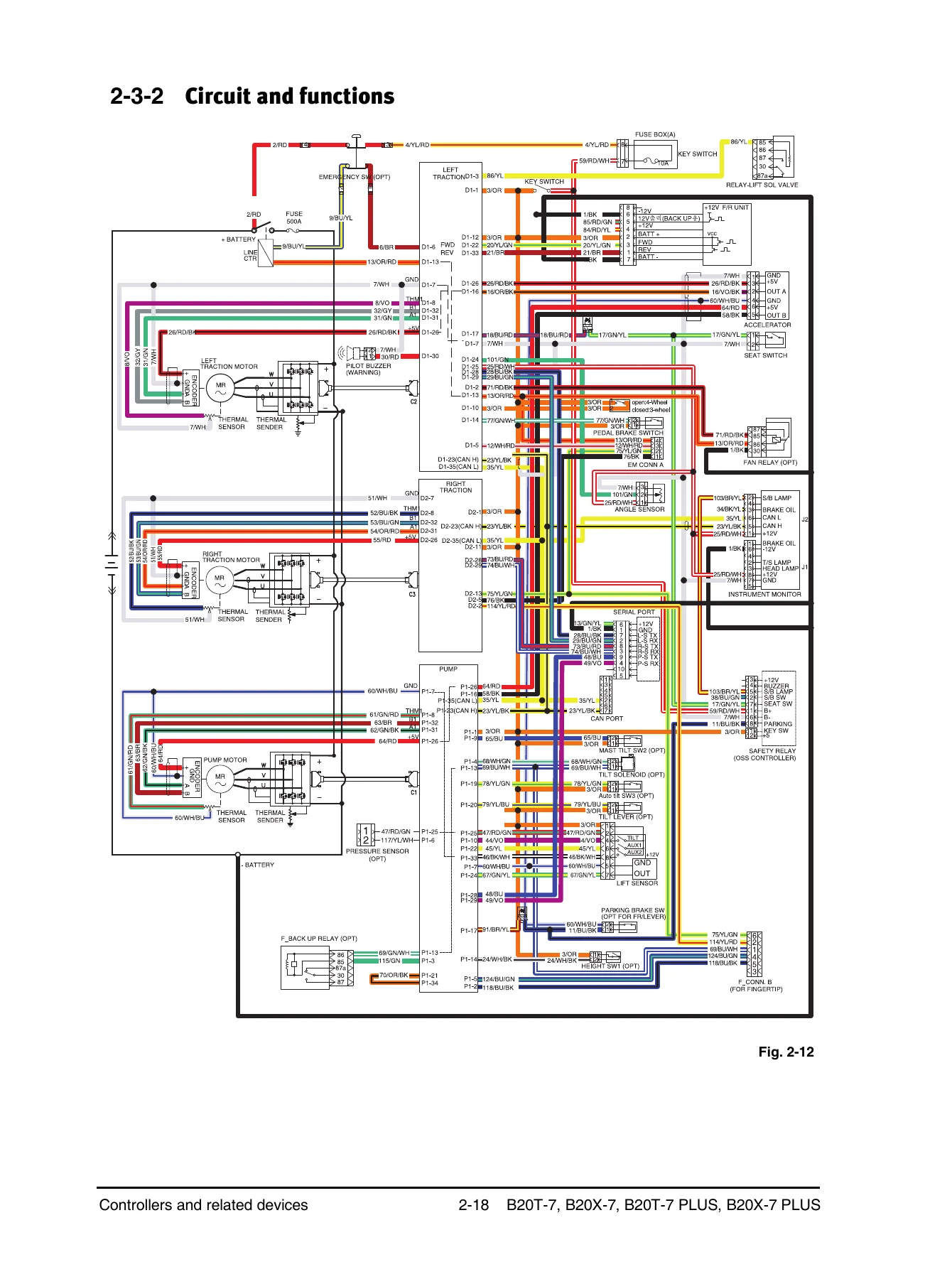
Exploded component views show how assemblies go together and come apart, hydraulic schematics show oil flow through the priority valve and control valve in neutral, lift, lower, tilt and auxiliary positions, and the electrical schematics at the end of the manual trace the full harness for both master cylinder brake and Electric Foot Brake trucks. A dedicated fault chapter lists instrument panel fault codes with fault level, probable cause and the checks to run for contactor faults, encoder faults, thermal sensor faults, EM brake faults, CAN communication faults, over-temperature conditions, solenoid faults and fingertip option faults.

Complete PDF Bookmark Tree

Complete Bookmarks

The complete bookmarks in the β€œDoosan B15/18/20T-7, B18/20TL-7, B16/18/20X-7 PLUS Electric Forklift Service Manual – SB4449E05” are as follows:

B20T-7(PLUS) B20X-7(PLUS)_SB4449E05p. 1
Forewordp. 2
Contentsp. 4
1 Generalp. 6
1-1 How to use this manualp. 7
1-1-1 Construction of this manualp. 7
1-1-2 Warning label definitionp. 9
1-2 Glossaryp. 10
1-3 Exterior and specificationsp. 14
1-3-1 B15/18/20T-7 and B18/20TL-7p. 14
1-3-2 B15/18/20T-7 PLUSp. 20
1-3-3 B16/18/20X-7p. 25
1-3-4 B16/18/20X-7 PLUSp. 29
1-4 Safety precautionsp. 32
1-5 Maintenancep. 39
1-6 Lubricantsp. 44
1-6-1 Recommended viscosities and capacitiesp. 44
1-6-2 Lubricant specificationsp. 45
1-6-3 Greasing pointsp. 47
1-7 Disassembly/assembly instructionsp. 51
1-8 Standard torquesp. 60
1-8-1 Standard torques for bolts and nutsp. 60
1-8-2 Standard torques for tightening fittingsp. 62
2 Electrical systemp. 66
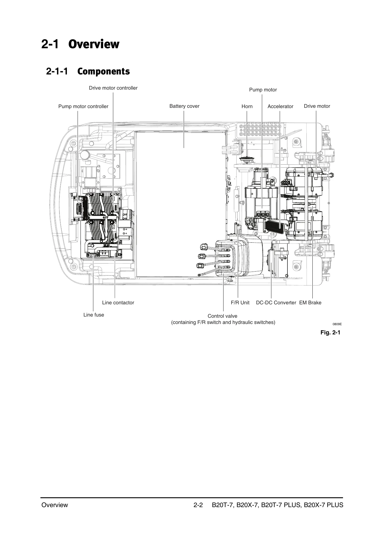
2-1 Overviewp. 67
2-1-1 Componentsp. 67
2-1-2 Communication protocolp. 69
2-2 Batteryp. 71
2-2-1 Exterior and specificationsp. 71
2-2-2 Functionsp. 73
2-2-3 Wiringp. 75
2-2-4 Testp. 76
2-2-5 Maintenancep. 79
2-2-6 Removal and installationp. 81
2-3 Controllers and related devicesp. 82
2-3-1 Exterior and specificationsp. 82
2-3-2 Circuit and functionsp. 83
2-3-3 Wiringp. 85
2-3-4 LED fault codesp. 88
2-3-5 Testp. 89
2-3-6 Removal and installationp. 91
2-4 Miscellaneous loadsp. 94
2-4-1 Fuse boxp. 94
2-4-2 DC-DC converterp. 97
2-4-3 Lamp groupp. 100
2-4-4 OSS controllerp. 101
2-4-5 Hornp. 103
2-4-6 Optional speed limitp. 104
2-4-7 Schematicp. 107
2-5 Instrument panelp. 108
2-5-1 Display and buttonsp. 108
2-5-2 Diagnosisp. 113
2-5-3 Calibrationp. 117
2-6 Application β€œEasyView”p. 123
2-6-1 Installation and executionp. 123
2-6-2 Controller firmware updatep. 129
2-6-3 β€œAdministration” menu descriptionp. 133
2-6-4 β€œTools” menu descriptionp. 134
2-6-5 Main page – Test Menup. 143
2-6-6 Main page – Calibration Menup. 151
2-6-7 Initial settingsp. 175
2-7 Handling faults on instrument panel/EasyView
3 Drive/brake systemp. 203
3-1 Overviewp. 204
3-1-1 Componentsp. 204
3-2 Drive motorp. 206
3-2-1 Exterior and specificationsp. 206
3-2-2 How it worksp. 208
3-2-3 Drive motor/axle/EM brake removal/installationp. 210
3-2-4 Drive motor disassembly/assembly and testp. 212
3-2-5 Drive wheel removal/installationp. 214
3-3 Drive axlep. 215
3-3-1 Exterior and specificationsp. 215
3-3-2 How it worksp. 216
3-3-3 Drive axle oil replacementp. 219
3-3-4 Adjustmentp. 220
3-3-5 Disassembly and assemblyp. 221
3-4 Acceleratorp. 226
3-4-1 Exterior and specificationsp. 226
3-4-2 How it worksp. 227
3-4-3 Removal and installationp. 228
3-5 F/R unitp. 229
3-5-1 Exterior and specificationsp. 229
3-5-2 How it worksp. 230
3-5-3 Removal/Installationp. 232
3-6 Service brake pedal ass’yp. 233
3-6-1 Exterior and specificationsp. 233
3-6-2 How it worksp. 234
3-6-3 Brake pedal adjustmentp. 238
3-6-4 Air removal in brake oilp. 239
3-6-5 Brake pedal ass’y removal/installationp. 241
3-6-6 Master cylinder disassembly/assemblyp. 243
3-7 Electric Foot Brakep. 244
3-7-1 Exterior and specificationsp. 244
3-7-2 How it worksp. 246
3-7-3 Brake pedal ass’y removal/installationp. 248
3-7-4 Brake pedal adjustmentp. 250
3-8 EM parking brakep. 253
3-8-1 Exterior and specificationsp. 253
3-8-2 How it worksp. 254
3-8-3 Parking brake testp. 255
3-8-4 Manual release of brakingp. 256
3-9 Troubleshootingp. 257
3-9-1 Drivingp. 257
3-9-2 Service brakep. 259
3-9-3 EM parking brakep. 260
4 Hydraulic systemp. 261
4-1 Overviewp. 262
4-1-1 Componentsp. 262
4-1-2 Oil flowp. 264
4-2 Pump motorp. 266
4-2-1 Exterior and specificationsp. 266
4-2-2 How it worksp. 268
4-2-3 Pump motor and main hydraulic pump removal/installationp. 270
4-2-4 Pump motor disassembly/assembly and testp. 272
4-3 Main hydraulic pumpp. 274
4-3-1 Exterior and specificationsp. 274
4-3-2 How it worksp. 275
4-3-3 Removal and installationp. 276
4-4 Priority valvep. 278
4-4-1 Exterior and specificationsp. 278
4-4-2 How it worksp. 279
4-4-3 Removal and installationp. 280
4-4-4 Disassembly and assemblyp. 281
4-5 Hydraulic tank and filterp. 282
4-5-1 Exterior and specificationsp. 282
4-5-2 How it worksp. 284
4-5-3 Hydraulic oil and filter replacementp. 286
4-6 Troubleshootingp. 287
5 Lift/tilt/auxiliary systemp. 288
5-1 Overviewp. 289
5-1-1 Componentsp. 289
5-1-2 Oil flowp. 291
5-2 Control valvep. 293
5-2-1 Exterior and specificationsp. 293
5-2-2 How it worksp. 294
5-2-3 Relief valve adjustmentp. 305
5-2-4 Needle valve for emergent loweringp. 308
5-2-5 Levers and switch group adjustment/removal/installationp. 309
5-2-6 Control valve removal/installationp. 311
5-2-7 Control valve disassembly/assemblyp. 313
5-3 Mast ass’yp. 315
5-3-1 Exterior and specificationsp. 315
5-3-2 How it worksp. 317
5-3-3 Forks servicep. 325
5-3-4 Sideshifter servicep. 327
5-3-5 Chains servicep. 333
5-3-6 Tilt cylinders servicep. 339
5-3-7 Primary lift cylinders servicep. 347
5-3-8 Standard/secondary cylinders servicep. 351
5-3-9 Carriage servicep. 361
5-3-10 Mast servicep. 365
5-4 Quad mastp. 371
5-4-1 Primary lift cylinder servicep. 371
5-4-2 Standard cylinder servicep. 374
5-4-3 Carriage servicep. 386
5-5 GSS and auto-tilt leveling optionsp. 387
5-5-1 Exterior and specificationsp. 387
5-5-2 How it worksp. 389
5-5-3 Height switch removal/installationp. 392
5-5-4 Mast tilt/auto-tilt switch ass’y removal/installationp. 393
5-5-5 Hydraulic block ass’y removal/installationp. 395
5-6 Troubleshootingp. 397
6 Steering systemp. 399
6-1 Overviewp. 400
6-1-1 Componentsp. 400
6-1-2 Oil flowp. 402
6-2 Steering control groupp. 404
6-2-1 Exterior and specificationsp. 404
6-2-2 How it worksp. 406
6-2-3 Steering system air removalp. 413
6-2-4 Steering system pressure checkp. 414
6-2-5 Steering wheel cover removal/installationp. 416
6-2-6 Steering wheel removal/installationp. 417
6-2-7 Steering wheel column removal/installationp. 418
6-2-8 Steering unit disassembly/assemblyp. 420
6-3 Steering operation group [B15/18/20T (TL)]p. 422
6-3-1 Exterior and specificationsp. 422
6-3-2 How It worksp. 424
6-3-3 Steer angle sensor removal/installationp. 426
6-3-4 Rear wheel and hub adjustment/removal/installationp. 427
6-3-5 Steer axle spindle removal/installation/disassembly/assemblyp. 430
6-3-6 Steer axle housing ass’y disassembly/assemblyp. 432
6-4 Steering operation group [B16/18/20X]p. 434
6-4-1 Exterior and specificationsp. 434
6-4-2 How it worksp. 436
6-4-3 Steer angle sensor removal/installationp. 438
6-4-4 Rear wheel and hub adjustment/removal/installationp. 439
6-4-5 Steer axle removal/installationp. 442
6-4-6 Link ass’y removal/installationp. 444
6-4-7 Steering knuckle, king pin, and bearing removal/installationp. 445
6-4-8 Steering cylinder removal/installation/disassembly/assemblyp. 446
6-5 Troubleshootingp. 448
7 Framep. 450
7-1 Hood removal/installationp. 451
7-2 Overhead guard removal/installationp. 453
7-3 Floor plates removal/installationp. 454
7-4 Top cover and counterweightremoval/installationp. 455
7-5 Modular cabin removal/installationp. 457
7-5-1 A typep. 457
7-5-2 B typep. 459
7-5-3 C typep. 460
7-5-4 Electric schematic for cabinp. 461
7-6 Heaterp. 462
7-6-1 Exterior and Specificationsp. 462
7-6-2 Operating conditionp. 462
7-6-3 Operating modep. 462
7-6-4 Maintenance informationp. 463
7-6-5 Troubleshootingp. 464
8 Fingertip optionp. 465
8-1 Overviewp. 466
8-1-1 Components and circuitp. 466
8-2 Fingertip extension modulep. 468
8-2-1 Exterior and specificationsp. 468
8-2-2 Circuit configuration and key functionsp. 469
8-2-3 Wiringp. 470
8-2-4 Removal and installationp. 471
8-3 Fingertip armrest unitp. 472
8-3-1 Exterior and specificationsp. 472
8-3-2 Circuit configuration and key functionsp. 474
8-3-3 Wiringp. 475
8-3-4 Hydraulic control knobsp. 476
8-3-5 Forward/reverse switchp. 477
8-3-6 Removal and installationp. 478
8-3-7 Disassembly and assemblyp. 479
8-4 Control valve – Kayaba (–Jul. 2018)p. 483
8-4-1 Exterior and specificationsp. 483
8-4-2 Wiringp. 485
8-4-3 How it worksp. 486
8-4-4 Relief valve adjustmentsp. 498
8-4-5 Manual loweringp. 502
8-4-6 Removal and installationp. 503
8-4-7 Disassembly and assemblyp. 504
8-5 Control valve – Walvoil (Jul. 2018–)p. 505
8-5-1 Exterior and specificationsp. 505
8-5-2 Wiringp. 507
8-5-3 How it worksp. 508
8-5-4 Relief valve adjustmentsp. 520
8-5-5 Manual loweringp. 522
8-5-6 Disassembly and assemblyp. 523
8-6 Steering pressure switch ass'yp. 525
8-6-1 Exterior and specificationsp. 525
8-6-2 Wiringp. 525
8-6-3 Pump motor operation at steeringp. 526
8-7 Fault diagnosisp. 528
8-7-1 Fault displayp. 528
8-7-2 Troubleshootingp. 529
9 Schematicsp. 545
Hydraulic Schematicp. 545
Hydraulic Schematic – Fingertip-Kayabap. 546
Hydraulic Schematic – Walvoilp. 547
Electric Schematic (Master Cylinder Brake)p. 548
Electric Schematic (Electric Foot Brake)p. 549
Electric Schematic (Electric Foot Brake, 1/4)p. 550
Electric Schematic (Electric Foot Brake, 2/4)p. 551
Electric Schematic (Electric Foot Brake, 3/4)p. 552
Electric Schematic (Electric Foot Brake, 4/4)p. 553
Indexp. 554
Revision historyp. 558

Get the Doosan B15/18/20T-7, B18/20TL-7, B16/18/20X-7 PLUS Electric Forklift Service Manual – SB4449E05

IMAGES PREVIEW

Doosan B15/18/20T-7, B18/20TL-7, B16/18/20X-7 PLUS Electric Forklift Service Manual - SB4449E05 β€” PDF page 1 preview
Doosan B15/18/20T-7, B18/20TL-7, B16/18/20X-7 PLUS Electric Forklift Service Manual - SB4449E05 β€” PDF page 67 preview
Doosan B15/18/20T-7, B18/20TL-7, B16/18/20X-7 PLUS Electric Forklift Service Manual - SB4449E05 β€” PDF page 83 preview

Whether you maintain a mixed fleet of T, TL, X and PLUS trucks or you are rebuilding a single machine, having the Doosan B15/18/20T-7, B18/20TL-7, B16/18/20X-7 PLUS Electric Forklift Service Manual – SB4449E05 on hand means you work to Doosan’s own procedures and specification values instead of estimating them. Every disassembly step, torque figure, pressure setting and fault-code diagnosis in this PDF exists so the truck goes back into service correctly and stays there. The manual is delivered as an instant PDF download after payment – no shipping, no waiting, and you can open it on a laptop, tablet or phone in the workshop or print the pages you need for the job.
Reviews

There are no reviews yet.

Be the first to review “Doosan B15/18/20T-7, B18/20TL-7, B16/18/20X-7 PLUS Electric Forklift Service Manual – SB4449E05”

What Our Customers Say

β˜…β˜…β˜…β˜…β˜… Live reviews from customers
Loading customer reviews...
0
    0
    Your Cart
    Your cart is emptyReturn to Shop
    πŸ›’
    Recently Purchased
    πŸ•’ verified order