★ TRUSTED BY 321,897+ PROFESSIONALS WORLDWIDE
🏒
Trusted Business
Verified & Licensed
πŸ›‘οΈ
Virus Free Files
100% Safe Downloads
πŸ”’
Secure Payment
SSL Protected
⚑
Instant Delivery
Available Immediately
Sale!

Doosan D60S-5 D70S-5 Forklift Parts Catalogue SB1113E10 – 3 Speed Transmission

Original price was: $39.95.Current price is: $24.95.

Complete Doosan D60S-5 and D70S-5 forklift parts catalogue covering the 3 Speed Transmission, HMC D439E Tier 3 diesel engine, brake system, power train, hydraulic mast, and every serviceable component with part numbers, serial number ranges, and exploded-view diagrams.

⚑
Instant PDF Download
Available immediately
πŸ’Ύ
Save to Your Device
Download & keep forever
πŸ›‘οΈ
Antivirus Scanned
100% virus-free
🌍
Trusted Worldwide
175,000+ customers

Description

Doosan D60S-5 D70S-5 Forklift Parts Catalogue SB1113E10

This is the complete parts catalogue for the Doosan D60S-5 and D70S-5 forklifts equipped with the 3 Speed Transmission and HMC D439E Tier 3 diesel engine. Document SB1113E10 covers every serviceable component across the chassis, engine, brake system, power train, hydraulic mast, and implements. Whether you are rebuilding a transmission, sourcing a hydraulic cylinder seal kit, or identifying a replacement electrical component, this Doosan forklift parts catalogue gives you the exact part numbers and exploded-view diagrams you need.

File Details

  • Manual Type: Parts Catalogue
  • Brand: Doosan
  • Models Covered: D60S-5, D70S-5
  • Engine: HMC D439E Tier 3 Diesel
  • Transmission: 3 Speed
  • Document Number: SB1113E10
  • Language: English
  • File Format: PDF
  • Page Count: 626

Chapters Covered

  • Chassis Component – Steer axle group, steering cylinder assembly, drive axle and steer axle mounting, engine and transmission group, flywheel group, fan drive group, power train mounting, intake and exhaust group, coolant lines, cooler lines, mast operating lines, pump assembly, hydraulic oil filter group, priority valve assembly, hood group, battery group, wiring group, lamp assemblies, tilt mounting, frame group
  • Capacity Module – Counterweight group, pneumatic tire and wheel group, solid tire and wheel group, overhead guard assembly, location chart
  • Engine – Cylinder block, front case, oil pan and rear plate, engine attach, cylinder head and thermostat, rocker cover, crankshaft and flywheel and piston, timing system, water pump, pulley, oil pump and filter, oil cooler, oil level gauge and guide, oil line, turbocharger, exhaust manifold, fuel injection pipe and nozzle, fuel hose, fuel return hose, injection pump, starter, glow plug, alternator, vacuum pump and gear case, sensor, engine wiring, supplying parts
  • Brake System – Parking group for F.C.U (STD and Cabin), brake lines, master cylinder sub-assembly, control group for accel and brake and inching, pedal mount group
  • Power Train – Drive axle group, transmission, engine connect group, converter, input group, gear box housing groups, coupling groups, output groups, IND. transmitter, control unit group, pressure oil pump group, temperature sensor, filter, dipstick group
  • Option for Complete Truck – Back mirror group, tool group, seat groups (suspension, static, vinyl, cloth), seat belt indicator group, change over arrangements for cabin, cabin assemblies with and without heater, lighting wiring group, heater group, air conditioner group, cabin group for aircon, airconditioner group, changeover arrangements for hood lock, US DS type, engine shut down, horizontal exhaust, muffler options, modular B type cabin, rear view system, CD player, deluxe cabin groups
  • Option for General – Operator cell group, front cockpit unit, steering group, cover group, harness group instrument, valve groups for 2, 3, 4, and 5 spool configurations, RCV valve groups, lift section valve assembly, tilt section valve assembly, auxiliary section valve assembly, main body assembly, diesel safety group, hydraulic oil cooler lines, auto tilt leveling group, engine block heater group
  • Mast-Hydraulic – Mounting groups for lift (STD and FFT), attachment line groups (3-way, 4-way, 5-way; STD and FFT), tilt cylinder group, sideshift cylinder groups (shaft type and hook-on type), lift cylinder groups (STD, FFT primary and secondary)
  • Mast-Implements – Mounting groups for mast, mast basic groups (STD and FFT), mast assemblies, relay groups for lift, carriage assemblies, mounting groups for carriage, sideshift carriage assemblies, mounting groups for backrest assembly, attachment mounting groups, carriage arrangements for fork mover, mounting groups for fork mover, fork mover cylinders, fork assemblies

The Doosan D60S-5 D70S-5 parts book is organized into nine major groups covering the complete machine from the ground up. Every component is listed with its part number, quantity, description, and a reference to the illustration where it appears. The exploded-view diagrams let you see exactly how assemblies fit together, which is invaluable when ordering seals, bearings, gaskets, and hard-to-find components.

What This Parts Catalogue Covers

For the 3 Speed Transmission, you get detailed breakdowns of the coupling groups, clutch discs, pistons, bearings, gear box housings, and the torque converter. The hydraulic system is covered through the mast operating lines, priority valve, pump assembly, and the complete range of lift, tilt, and sideshift cylinders with their seal kits. The engine section drills down into the D439E Tier 3 diesel with individual part listings for the cylinder head, timing system, oil pump, turbocharger, injection pump, and all sensors.

Commonly needed maintenance parts are collected in a dedicated filters section, including the fuel filter (A453975), engine oil filter cartridge (A433754), transmission filter (A453462), hydraulic oil filter element kit (D501696), air cleaner primary element (A131768), air cleaner safety element (A131769), and hydraulic tank suction strainer (A135050). The cooling section lists the water pump assembly (A453765), thermostat housing gaskets (A433764, A453684), cooling fan (A453564), fan belt (A453579), V-belt for water pump and alternator (A433756), radiator cap (D460972), and radiator inlet and outlet hoses (A452848, A452849).

Complete PDF Bookmark Tree

Complete Bookmarks

The complete bookmarks in the β€œDoosan D60S-5 D70S-5 Forklift Parts Catalogue SB1113E10 – 3 Speed Transmission” are as follows:

D60S-5, D70S-5 (SB1113E10)p. 1
Forewordp. 3
Common Part Listp. 5
Maintenance Partp. 8
Contentsp. 10
Quick Reference Guide To Major Sectionsp. 17
Fig.1 CHASSIS COMPONENTp. 18
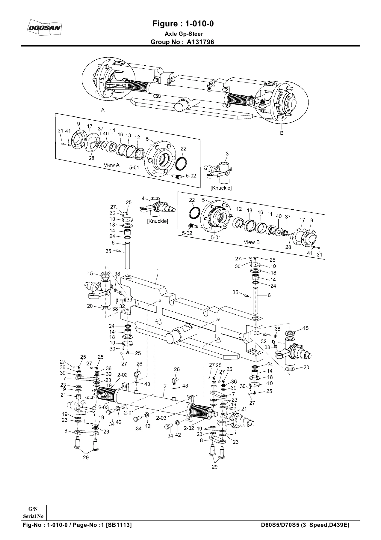
Fig.1-010-0 Axle Gp-Steerp. 20
Fig.1-010-1 Cylinder Ass’yp. 22
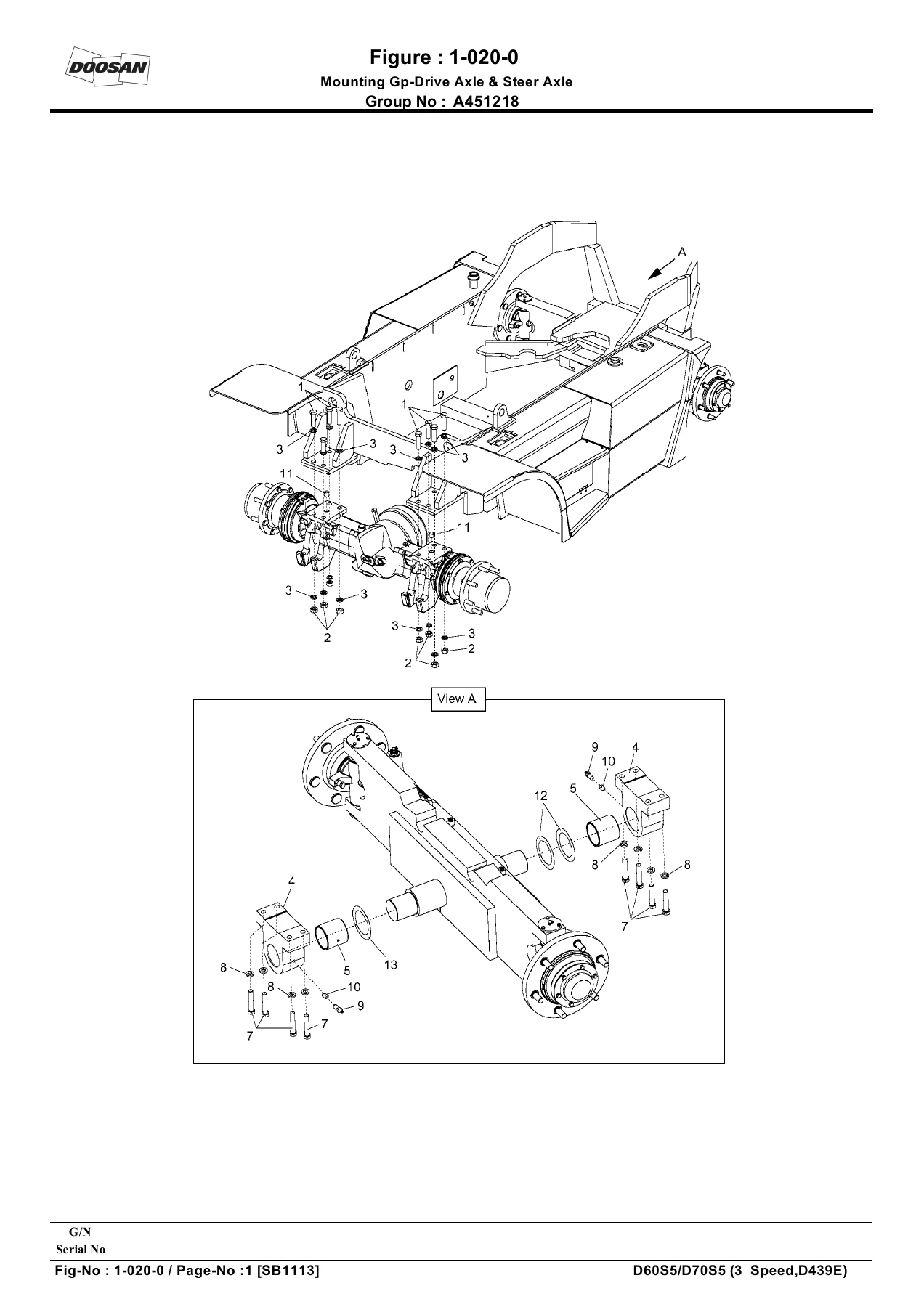
Fig.1-020-0 Mounting Gp-Drive Axle & Steer Axlep. 24
Fig.1-030-0 Engine & Transmission Gpp. 26
Fig.1-030-0-1 Engine & Transmission Gpp. 28
Fig.1-030-1 Flywheel Gpp. 30
Fig.1-030-2 Fan Drive Gpp. 32
Fig.1-030-2-1 Fan Drive Gpp. 34
Fig.1-040-0 Mounting Gp-Power Trainp. 36
Fig.1-040-0-1 Mounting Gp-Power Trainp. 38
Fig.1-050-0 Intake & Exahust Gp – part 1 of 2p. 40
Fig.1-050-0 Intake & Exahust Gp – part 2 of 2p. 42
Fig.1-060-0 Lines Gp-Coolant – Engine & Transmission & Fuelp. 44
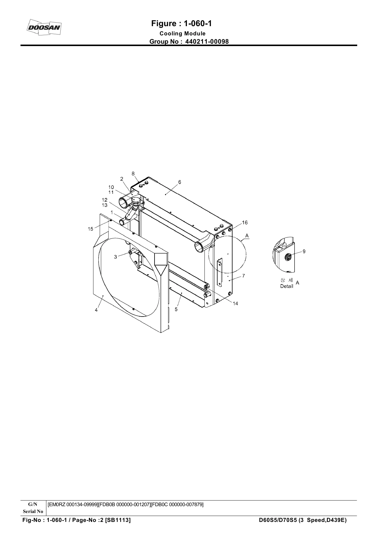
Fig.1-060-1 Cooling Modulep. 46
Fig.1-070-0 Lines Gp-Coolerp. 52
Fig.1-080-0 Lines Gp-Mast Operating – OCD Type Brakep. 54
Fig.1-080-1 Pump Ass’yp. 58
Fig.1-080-2 Filter Gp – Hydrulic Oilp. 62
Fig.1-080-3 Valve Ass’y Priorityp. 64
Fig.1-090-0 Hood Gpp. 68
Fig.1-090-1 Hood Ass’yp. 70
Fig.1-100-0 Battery Gpp. 72
Fig.1-110-0 Wiring Gp – part 1 of 2p. 74
Fig.1-110-0 Wiring Gp – part 2 of 2p. 76
Fig.1-110-1 Lamp Ass’y-LHp. 78
Fig.1-110-1 Lamp Ass’y-RHp. 80
Fig.1-120-0 Mounting Gp-Tiltp. 82
Fig.1-130-0 Frame Gpp. 84
Fig.1-130-0-1 Frame Gpp. 86
Fig.2 CAPACITY MODULEp. 88
Fig.2-010-0 Countweight Gpp. 90
Fig.2-020-0 Tire & Wheel Gp, Pneumaticp. 92
Fig.2-030-0 Tire & Wheel Gp, Solidp. 94
Fig.2-040-0 Guard Ass’y-Overheadp. 96
Fig.2-050-0 Location Chart – PART 1 OF 2p. 98
Fig.2-050-0 Location Chart – PART 2 OF 2p. 100
Fig.3 ENGINEp. 102
Fig.3-010-0 Cylinder Blockp. 104
Fig.3-020-0 Front Casep. 106
Fig.3-030-0 Oil Pan & Rear Platep. 108
Fig.3-040-0 Engine Attachp. 110
Fig.3-050-0 Cylinder Head & Thermostatp. 112
Fig.3-060-0 Rocker Coverp. 114
Fig.3-070-0 Crank Shaft & Flywheel & Pistonp. 116
Fig.3-080-0 Timing Systemp. 118
Fig.3-090-0 Water Pumpp. 120
Fig.3-100-0 Pulleyp. 122
Fig.3-110-0 Oil Pump & Filterp. 124
Fig.3-120-0 Oil Coolerp. 126
Fig.3-130-0 Oil Level Gauge & Guidep. 128
Fig.3-140-0 Oil Linep. 130
Fig.3-150-0 Turbo Chargerp. 132
Fig.3-160-0 Exhaust Manifoldp. 134
Fig.3-170-0 Fuel Injection Pipe & Nozzlep. 136
Fig.3-180-0 Fuel Hosep. 138
Fig.3-190-0 Fuel Return Hosep. 140
Fig.3-200-0 Injection Pumpp. 142
Fig.3-210-0 Starterp. 144
Fig.3-220-0 Glow-Plugp. 146
Fig.3-230-0 Alternatorp. 148
Fig.3-240-0 Vacuum Pump & Gear Casep. 150
Fig.3-250-0 Sensorp. 152
Fig.3-260-0 Engine Wiringp. 154
Fig.3-270-0 Suppling Partsp. 156
Fig.4 BRAKE SYSTEMp. 158
Fig.4-010-0 Parking Gp-F.C.U – STDp. 160
Fig.4-010-0 Parking Gp-F.C.U-Cabinp. 162
Fig.4-020-0 Lines Gp-Brake(OLD)p. 164
Fig.4-020-0 Lines Gp-Brake(NEW)p. 166
Fig.4-020-1 Cylinder Master Sub Ass’yp. 168
Fig.4-030-0 Control Gp-Accel & Brake & Inchingp. 172
Fig.4-030-1 Mount Gp-Pedalp. 174
Fig.5 POWER TRAINp. 176
Fig.5-010-0 Drive Axle Gp(1/3)p. 178
Fig.5-020-0 Drive Axle Gp(2/3)p. 180
Fig.5-030-0 Drive Axle Gp(3/3)p. 182
Fig.5-040-0 Transmissionp. 184
Fig.5-050-0 Engine Connect Gpp. 186
Fig.5-050-0 Converterp. 188
Fig.5-060-0 Input Gpp. 190
Fig.5-070-0 Gear Box Housing Gp – Part 1 of 2p. 192
Fig.5-070-1 Gear Box Housing Gpp. 194
Fig.5-070-2 Gear Box Housing Gp – Part 1 of 2p. 196
Fig.5-080-0 Gear Box Housing Gp – Part 2 of 2p. 198
Fig.5-090-0 Coupling Gpp. 200
Fig.5-090-1 Coupling Gpp. 202
Fig.5-100-0 Coupling Gpp. 204
Fig.5-100-1 Coupling Gpp. 206
Fig.5-110-0 Coupling Gpp. 208
Fig.5-120-0 Coupling Gpp. 210
Fig.5-130-0 Output Gp-1p. 212
Fig.5-130-0 Output Gp-2p. 214
Fig.5-140-0 IND. Transmitterp. 216
Fig.5-140-0 Control Unit Gpp. 218
Fig.5-150-0 Press. Oil Pump Gpp. 220
Fig.5-150-0 Temp. Sensorp. 222
Fig.5-160-0 Filterp. 224
Fig.5-160-0 Dipstick Gpp. 226
Fig.6 OPTION FOR COMPLETE TRUCKp. 228
Fig.6-010-0 Back Mirror Gpp. 230
Fig.6-010-1 Back Mirror Gp-Cabinp. 232
Fig.6-020-0 Tool Gpp. 234
Fig.6-030-0 Seat Gp-Suspension – Non NACDp. 236
Fig.6-040-0 Seat Gp-Suspension Arm Restp. 238
Fig.6-050-0 Seat Gp-Suspension – NACDp. 240
Fig.6-060-0 Seat Gp-Suspensionp. 242
Fig.6-070-0 Seat Gp-Static , Vinyl -Non NACDp. 244
Fig.6-070-1 Seat Assy-Static ,Vinyl -Non NACDp. 246
Fig.6-080-0 Seat Gp-Static,Vinyl (Hip Restrian)- NACDp. 248
Fig.6-080-1 Seat Assy-Static, Vinyl (Hip Restrian)- NACDp. 250
Fig.6-090-0 Seat Gp-Static,Cloth Non Logo (Hip Restrian)- NACDp. 252
Fig.6-090-1 Seat Assy-Static,Cloth Non Logo (Hip Restrian)- NACDp. 254
Fig.6-100-0 Seat Belt Indicator Gp – Non NACD & NACDp. 256
Fig.6-110-0 Change Over Ar.-Cabinp. 258
Fig.6-110-1 Cabin Ass’y-With Out Heater – With Out Heaterp. 260
Fig.6-110-1 Cabin Ass’y-With Heater – With Aircon & Heaterp. 262
Fig.6-120-0 Lighting Wiring Gp-Cabinp. 264
Fig.6-120-0 Lighting Wiring Gp-Cabin – part 2 of 2p. 266
Fig.6-130-0 Changeover Ar.-Heaterp. 268
Fig.6-130-1 Heater Gpp. 270
Fig.6-140-0 Changeover Ar.-Airconditionerp. 272
Fig.6-140-1 Cabin Gp-For Aircon.p. 274
Fig.6-140-2 Airconditioner Gpp. 276
Fig.6-150-0 Changeover Ar-Hood Lock – EUp. 278
Fig.6-160-0 Changeover Ar.-US DS Typep. 280
Fig.6-170-0 Changeover Ar.-Engine Shut Downp. 282
Fig.6-180-0 Changeover Ar.-Horizontal Exhaustp. 284
Fig.6-180-0 Changeover Ar.-Horizontal Exhaust – W/Catalytic Mufflerp. 286
Fig.6-180-0 Changeover Ar.-Horizontal Spark Arrestorp. 288
Fig.6-180-1 Muffler As – Spark Arrestorp. 290
Fig.6-190-0 Changeover AR.-Muffler Gp – 6 Ton/ 7 Tonp. 292
Fig.6-190-0 Chahgeover AR.-Vertial Exhaust & Spark Arrestor & Catalytic – (6/7 Ton)p. 294
Fig.6-200-0 Cabin Gp-Modular B Typep. 296
Fig.6-210-0 Changeover AR.-Rear Wiper Cabinp. 298
Fig.6-220-0 Cabin Modular-Rear View Systemp. 300
Fig.6-230-0 CD Player GP-STD Cabin Subp. 302
Fig.6-240-0 Changeover AR. CD Player-W/Cabinp. 304
Fig.6-250-0 Deluxe Cabin – With Heaterp. 306
Fig.6-250-1 Heater Gp – Deluxe Cabinp. 308
Fig.6-250-2 Floor Plate Assy- Deluxe Cabinp. 310
Fig.6-250-3 Insulation Gp- Deluxe Cabinp. 312
Fig.6-250-4 Electronic Gp- Deluxe Cabinp. 314
Fig.6-260-0 Cabin Gp – Deluxe Modularp. 316
Fig.6-260-1 Door Assy – Side (LH)- Deluxe Cabinp. 320
Fig.6-260-1 Door Assy – Side (RH)- Deluxe Cabinp. 322
Fig.6-270-0 Deluxe Cabin Gp – With Heater & Airconp. 324
Fig.6-270-1 Deluxe Cabin – Wiring Gpp. 326
Fig.6-280-0 Deluxe Cabin – Heater & Aircon Gpp. 328
Fig.6-280-1 Deluxe Cabin – Aircon Gpp. 330
Fig.7 OPTION FOR GENERALp. 332
Fig.7-010-0 Operator Cell Gpp. 336
Fig.7-010-0 Operator Cell Gp – Deluxep. 338
Fig.7-010-1 Operator Cell Modular – STDp. 340
Fig.7-010-1 Operator Cell Modular-Cabinp. 342
Fig.7-010-1-1 Floor Plate Gp – STDp. 344
Fig.7-010-1-1 Floor Plate Gp-Cabinp. 346
Fig.7-010-1-2 Lighting & Wiring Gp , STD – part 1 of 2p. 348
Fig.7-010-1-2 Lighting & Wiring Gp , STD – part 2 of 2p. 350
Fig.7-010-2 Instrument Gpp. 352
Fig.7-020-0 Front Cockpit Unit – STDp. 354
Fig.7-020-0 Front Cockpit Unit-Cabinp. 356
Fig.7-020-0 Front Cockpit Unit – Deluxe Cabinp. 358
Fig.7-020-1 Steering Gpp. 360
Fig.7-020-1 Steering Gp-Cabinp. 362
Fig.7-020-2 Cover Gp – Cabinp. 364
Fig.7-020-3 Harness Gp Instrumentp. 366
Fig.7-020-3-1 Switch Assy – Ignition (Key No. Table)p. 368
Fig.7-030-0 Valve Gp-2 Spoolp. 370
Fig.7-030-1 Main Control Valve Sub Ass’y-2 Spoolp. 372
Fig.7-030-2 Control Valve Ass’yp. 374
Fig.7-030-3 Pilot Valve Gp-2 Spoolp. 376
Fig.7-040-0 Valve Gp-3 Spoolp. 378
Fig.7-040-1 Main Control Valve Sub Ass’y-3 Spoolp. 380
Fig.7-040-2 Control Valve-3 Spoolp. 386
Fig.7-040-3 Pilot Valve Gp-3 Spoolp. 392
Fig.7-050-0 Valve Gp-4 Spoolp. 394
Fig.7-050-1 Main Control Valve Sub Ass’y-4 Spoolp. 396
Fig.7-050-2 Control Valve-4 Spoolp. 402
Fig.7-050-3 Pilot Valve Gp-4 Spoolp. 408
Fig.7-060-0 Valve Gp-5 Spoolp. 410
Fig.7-060-1 Main Control Valve Sub Ass’y-5 Spoolp. 412
Fig.7-060-2 Control Valve-5 Spoolp. 418
Fig.7-060-3 Pilot Valve Gp-5 Spoolp. 424
Fig.7-070-0 Valve Gp, RCV-2 Sectionp. 426
Fig.7-080-0 Valve Gp, RCV-3 Sectionp. 428
Fig.7-090-0 Valve Gp, RCV-4 Sectionp. 430
Fig.7-100-0 Valve Gp, RCV-5 Sectionp. 432
Fig.7-110-1 Lift Section Valve Ass’yp. 434
Fig.7-110-2 Tilt Section Valve Ass’yp. 436
Fig.7-110-3 Auxiliary Section Valve Ass’yp. 438
Fig.7-120-1 Lift Section Valve Ass’yp. 440
Fig.7-120-2 Tilt Section Valve Ass’yp. 442
Fig.7-120-3 Auxiliary Section Valve Ass’yp. 444
Fig.7-120-4 Main Body Ass’yp. 448
Fig.7-120-5 Body-SEC. Ass’yp. 450
Fig.7-120-6 Body Ass’yp. 454
Fig.7-130-0 Diesel Safety Gpp. 456
Fig.7-140-0 Lines Gp-Hyd Oil Collerp. 458
Fig.7-150-0 Auto Tilt Leveling Gp-Tier 3p. 460
Fig.7-160-0 Engine Block Heater Gpp. 462
Fig.8 MAST-HYDRAULICp. 464
Fig.8-010-0 Mounting Gp-Lift – STDp. 466
Fig.8-020-0 Mounting Gp-Lift – FFTp. 468
Fig.8-030-0 Lines Gp-ATT-Primary, 3 Way – STDp. 472
Fig.8-040-0 Lines Gp-ATT-Primary, 3 Way – FFTp. 474
Fig.8-050-0 Lines Gp-ATT-Primary, 4 Way – STDp. 476
Fig.8-060-0 Lines Gp-ATT-Primary, 4 Way – FFTp. 478
Fig.8-070-0 Lines Gp-ATT-Primary, 5 Way – STDp. 480
Fig.8-080-0 Lines Gp-ATT-Primary, 5 Way – FFTp. 482
Fig.8-090-0 Cylinder Gp-Tiltp. 484
Fig.8-100-0 Cylinder Gp-Sideshift – Shaft Typep. 486
Fig.8-110-0 Cylinder Gp-Sideshift – Hook On Typep. 488
Fig.8-120-0 Cylinder Gp-Lift – STDp. 490
Fig.8-130-0 Cylinder Gp-Lift – FFT-Primaryp. 492
Fig.8-140-0 Cylinder Gp-Lift – FFT-Secondaryp. 494
Fig.9 MAST-IMPLEMENTSp. 496
Fig.9-010-0 Mounting Gp-Mast – (STD, FFT)-Shoe Type Brakep. 498
Fig.9-020-0 Mounting Gp-Mast – (STD, FFT)-ODB Type Brakep. 500
Fig.9-030-0 Mast Gp – Basic-STDp. 502
Fig.9-040-0 Mast Gp – Basic-FFTp. 504
Fig.9-050-0 Mast Ass’y – STDp. 506
Fig.9-060-0 Mast Ass’y – FFTp. 508
Fig.9-070-0 Relay Gp-Lift – STDp. 510
Fig.9-080-0 Relay Gp-Lift – FFTp. 512
Fig.9-090-0 Carriage Ass’y – Shaft Typep. 514
Fig.9-100-0 Mounting Gp-Carriage – (6 Ton, STD)-Shaft Typep. 516
Fig.9-110-0 Mounting Gp-Carriage – (7 Ton, STD)-Shaft Typep. 518
Fig.9-120-0 Mounting Gp-Carriage – (6/7 Ton , FFT)-Shaft Typep. 520
Fig.9-130-0 Mounting Gp-Sideshift – (STD, FFT)-Shaft Typep. 522
Fig.9-140-0 Mounting Gp-Sideshift Carriage – (STD)-Shaft Typep. 524
Fig.9-150-0 Mounting Gp-Sideshift Carriage – (FFT)-Shaft Typep. 526
Fig.9-160-0 Roller Bracket Ass’y – (STD/FFT)-Shaft Typep. 528
Fig.9-170-0 Sideshift Carriage Ass’y – (STD)-Shaft Typep. 530
Fig.9-180-0 Carriage Ass’y – Hook On Typep. 532
Fig.9-190-0 Mounting Gp-Carriage – (6 Ton, STD)-Hook On Typep. 534
Fig.9-200-0 Mounting Gp-Carriage – (7 Ton, STD)-Hook On Typep. 536
Fig.9-210-0 Mounting Gp-Carriage – (FFT)-Hook On Typep. 538
Fig.9-220-0 Lines Gp-ATT-Sideshift – (STD)-Hook On Typep. 540
Fig.9-230-0 Lines Gp-ATT-Sideshift – (FFT)-Hook On Typep. 542
Fig.9-240-0 Sideshift Gp – (STD, FFT)-Hook On Typep. 544
Fig.9-250-0 Mounting Gp-Backrest Ass’y – Hook On Typep. 546
Fig.9-270-0 Mounting Gp-Attach – STDp. 548
Fig.9-280-0 Mounting Gp-Attach – FFTp. 550
Fig.9-290-0 Mounting Gp-Carriage Sideshift – Shaft Type, STDp. 552
Fig.9-290-0 Mounting Gp-Carriage Fork Moverp. 554
Fig.9-300-0 Mounting Gp-Carriage Sideshift – Shaft Type, FFTp. 556
Fig.9-300-0 Mounting Gp-Carriage Fork Moverp. 558
Fig.9-310-0 Carriage AR.-Fork Mover(Side Shifter & Fork Posioner) – Part 1 of 2p. 560
Fig.9-310-0 Carriage AR.-Fork Mover(Side Shifter & Fork Posioner) – Part 2 of 2p. 562
Fig.9-320-0 Mounting Gp-Fork Mover-4 Way – STDp. 564
Fig.9-320-0 Mounting Gp-Fork Mover-4 Way – FFTp. 566
Fig.9-320-1 Cylinder Ass’y-Fork Mover – STDp. 568
Fig.9-320-2 Cylinder Ass’y-Fork Mover-5 Wayp. 572
Fig.9-330-0 Mounting Gp-Fork Mover-5 Wayp. 574
Fig.9-330-0 Mounting Gp-Fork Mover-5 Way – FFTp. 576
Fig.9-340-0 Mounting Gp-Fork Mover-3 Way – STD- 6/7 Ton(Simultaneous Moving Type)p. 578
Fig.9-350-0 Mounting Gp-Fork Mover-4 Way – STD- 6/7 Ton(Independent Moving Type)p. 580
Fig.9-360-0 Mounting Gp-Fork Mover-3 Way – FFT- 6/7 Ton(Independent Moving Type)p. 582
Fig.9-370-0 Mounting Gp-Fork Mover-4 Way – FFT-6/7 Ton(Independent Moving Type)p. 584
Fig.9-380-0 Fork Ass’y – Shaft Typep. 586
Fig.9-390-0 Fork Ass’y – Hook On Typep. 588
Part Number Indexp. 591

The electrical section covers the starter motor (A433767), alternator assembly (A433766), horn assembly 24V (D187503), circuit breaker 60A (D544024), transmission control switch (A134026), ignition switch (A334112), key set (D554212), pressure switch (A214040), water temperature sensor (A453682), engine speed sensor (A453973), temperature sensors (A404057, A404054), oil pressure switch (A433786), relay assemblies (A234099, A124036), vehicle control system controller (A444003), glow plug (A453932), and ECU (A453972).

The brake system section includes the master cylinder for powered brake OCD type (A335006), master cylinder seal kit (D504725), hand brake switch assembly (D700116), brake plate (130113-00001), brake disk (130106-00001), and parking cable assembly (A451517).

The steering section covers the steer unit seal kit (A215283), needle bearing kit (A215284), steer cylinder seal kit (D511862), king pin (D700557), and the complete axle group components.

Beyond these, the catalogue also details the mast-hydraulic components including tilt cylinder seal kits, sideshift cylinder seal kits, lift cylinder seal kits for standard and FFT configurations, and the main pump seal kit for the gear pump.

Serial Number Ranges and Model Codes

The Doosan D60S-5 D70S-5 parts catalogue uses serial number ranges to identify which revision of a component fits your specific machine. The primary ranges covered include EM0RZ000001~000133, EM0RZ000134~, FDB0B000000~001177, FDB0B001178~, FDB0C000000~007211, and FDB0C007212~. The model codes are FDB0B for the D60S-5 and FDB0C for the D70S-5, with the engineering model number EM0RZ for the OCD Type Brake configuration. When Doosan updated a part number, this catalogue shows both the original and replacement numbers so you can cross-reference correctly.

Why This Parts Catalogue Matters

Ordering the wrong part for a forklift is expensive and time-consuming. This catalogue eliminates guesswork by giving you the exact part number for every component on the D60S-5 and D70S-5. The serial number ranges and model codes listed throughout help you identify which revision of a component fits your particular machine. The exploded-view diagrams provide visual confirmation that you are ordering the correct part, and the replacement part number columns help you cross-reference superseded components.

For fleet mechanics and independent technicians, having the complete parts catalogue means faster repairs, fewer ordering mistakes, and the ability to quickly quote parts for customers. For owner-operators, it means being able to identify and order the right parts without relying on a dealer’s parts counter. The inclusion of optional equipment sections – covering cabins, heaters, air conditioners, seats, mirrors, and attachments – means this single catalogue covers virtually every configuration of the D60S-5 and D70S-5 that left the factory.

IMAGES PREVIEW

Doosan D60S-5 D70S-5 Forklift Parts Catalogue SB1113E10 - 3 Speed Transmission β€” PDF page 20 preview
Doosan D60S-5 D70S-5 Forklift Parts Catalogue SB1113E10 - 3 Speed Transmission β€” PDF page 24 preview
Doosan D60S-5 D70S-5 Forklift Parts Catalogue SB1113E10 - 3 Speed Transmission β€” PDF page 48 preview

Instant PDF Delivery

This Doosan D60S-5 D70S-5 forklift parts catalogue is delivered as an instant PDF download – no shipping, no waiting. Access it on any device, print the pages you need for the workshop, and keep the complete parts reference on hand for every repair and maintenance job. Whether you are a fleet mechanic, an independent technician, or an owner-operator, having the correct parts catalogue for your D60S-5 or D70S-5 means faster repairs and fewer ordering mistakes.
Reviews

There are no reviews yet.

Be the first to review “Doosan D60S-5 D70S-5 Forklift Parts Catalogue SB1113E10 – 3 Speed Transmission”

What Our Customers Say

β˜…β˜…β˜…β˜…β˜… Live reviews from customers
Loading customer reviews...
0
    0
    Your Cart
    Your cart is emptyReturn to Shop
    πŸ›’
    Recently Purchased
    πŸ•’ verified order