Doosan DX225LCA Excavator Shop Manual – Serial 5167 and Up (Pub. K1049156E) PDF Download
$44.95 Original price was: $44.95.$26.95Current price is: $26.95.
Complete 792-page Doosan DX225LCA Shop Manual (Pub. No. K1049156E) covering serial number 5167 and up, with full specifications, hydraulic and electrical schematics, and component repair procedures. Instant PDF download.
Description
Doosan DX225LCA Excavator Shop Manual – Serial 5167 and Up (K1049156E)
This is the complete factory-issued Doosan DX225LCA Shop Manual, Publication No. K1049156E, covering the DX225LCA track excavator for serial number 5167 and up. The Doosan DX225LCA Shop Manual runs 792 pages and is organized into individually numbered service sections (SP numbers) exactly as Doosan issued them, so every system on the excavator is documented in one searchable PDF instead of scattered binder inserts.
File Details
- Manual Type: Shop Manual
- Brand / Model: Doosan DX225LCA
- Applicable Serial Number Range: 5167 and Up
- Publication Number: K1049156E
- Language: English
- Page Count: 792 pages
- File Format: PDF
- Copyright: 2008 Doosan
Chapters Covered
The DX225LCA Shop Manual is broken into the following sections, matching the original table of contents:
- Safety
- Track Excavator Safety
- Specifications
- Specification for DX225LCA (general dimensions, working range, general specifications, engine performance curves, performance tests)
- General Maintenance
- General Maintenance Procedures
- Standard Torques
- Upper Structure
- Cabin
- Counterweight
- Fuel Tank
- Fuel Transfer Pump
- Swing Bearing
- Swing Reduction Gear
- Lower Structure and Chassis
- Track Assembly
- Engine and Drive Train
- Drive Coupling (Main Pump)
- Hydraulics
- Hydraulic System Troubleshooting, Testing and Adjustment
- Accumulator
- Center Joint (Swivel)
- Cylinders
- Swing Motor
- Travel Motor
- Gear Pump
- Main Control Valve
- Axial Piston Pump
- PTO Server
- Remote Control Valve (Work Lever / Joystick)
- Travel Control Valve (with Damper)
- Solenoid Valve Assembly
- Breaker EPPR Valve (Opt)
- Hydraulic Schematic (DX225LC/DX225LCA)
Complete PDF Bookmark TreeComplete Bookmarks
The complete bookmarks in the “Doosan DX225LCA Excavator Shop Manual – Serial 5167 and Up (Pub. K1049156E) PDF Download” are as follows:
Table of Contentsp. 5+Safetyp. 7
+Track Excavator Safetyp. 9
Safety Precautionsp. 13Applicable Modelsp. 13+To the Operator of a DOOSAN Excavatorp. 15
Learn the Signal Words Used with the Safety Alert Symbolp. 17+General Safety Essentialsp. 18
Accessory Applicationsp. 18Lifting Capacity Rating Configurationp. 18Location of Safety Labelsp. 19Summary of Safety Precautions for Lifting in Digging Modep. 19Unauthorized Modificationsp. 20+General Hazard Informationp. 20
Safety Rulesp. 20Safety Featuresp. 21Inside Operator's Compartmentp. 21Clothing and Personal Protective Itemsp. 22Breathing Masks, Ear Protection May Be Requiredp. 22Vibration Level Informationp. 22Recommendations for Limiting Vibrationsp. 23Mounting and Dismountingp. 24Fuel, Oil and Hydraulic Fluid Fire Hazardsp. 24Precautions When Handling Fluids at High Temperaturep. 25Asbestos Dust Hazard Preventionp. 25Injury from Work Equipmentp. 26Fire Extinguisher and First Aid Kitp. 26Protection from Falling or Flying Objectsp. 27Attachment Precautionsp. 27Accumulatorp. 28Indoor Ventilationp. 28Emergency Exitp. 29+Before Starting Enginep. 29
Work Site Precautionsp. 29Checks Before Starting Enginep. 30Engine Startingp. 31Before Operating Machinep. 32+Machine Operationp. 33
When Swinging or Changing Direction of Travelp. 33Travel Precautionsp. 34Traveling on Slopesp. 35Prohibited Operationsp. 35Precautions for Operationp. 36Avoid High Voltage Cablesp. 37Protecting Cabin from Falling Object (Optional)p. 37Operate Carefully on Snow, Ice and in Very Cold Temperaturesp. 38Operations on Slopesp. 38Parking Machinep. 39Never Let Anyone Ride on Attachmentp. 39+Maintenancep. 40
Warning Tagp. 40Clean Before Inspection or Maintenancep. 40Proper Toolsp. 41Use of Lightingp. 41Fire Prevention and Explosion Preventionp. 41Burn Preventionp. 42Welding Repairsp. 43Warning for Counterweight and Front Attachment Removalp. 43Precautions for Removal, Installation, and Storage of Attachmentsp. 44Precautions When Working on Machinep. 44Lock Inspection Coversp. 44Crushing Prevention and Cutting Preventionp. 44Track Tension Adjustments Require Cautionp. 45Supports and Blocking for Work Equipmentp. 45Action When Abnormality Is Found During Inspectionp. 45Precautions with High-pressure Lines, Tubes and Hosesp. 46Waste Materialsp. 47+Batteryp. 48
Battery Hazard Preventionp. 48Boost Starting or Charging Engine Batteriesp. 49+Towingp. 50
Precautions When Towingp. 50+Shipping and Transportationp. 51
Obey State and Local Over-the-Road Regulationsp. 51Lifting With Slingp. 51+Specificationsp. 53
+Specification for DX225LCAp. 55
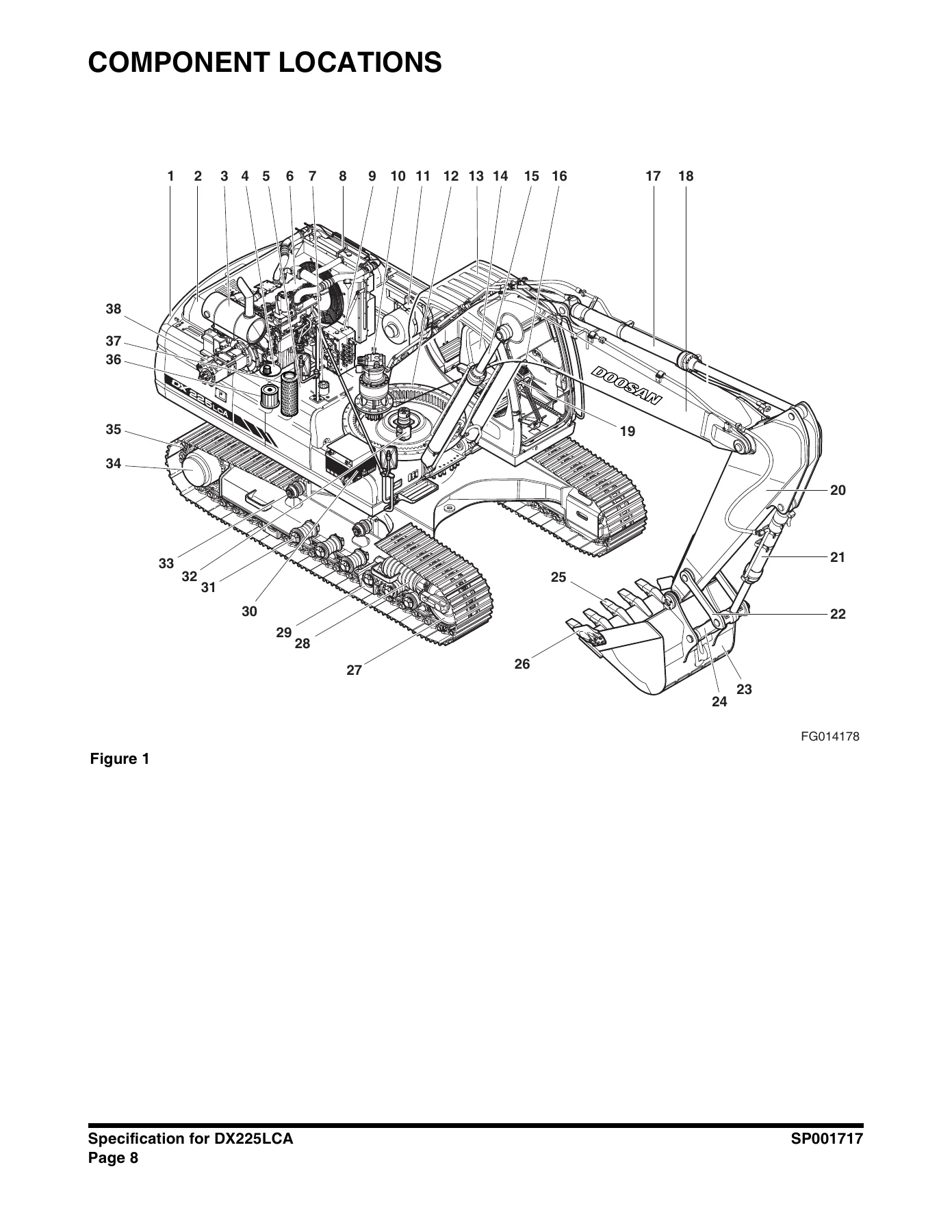
Safety Precautionsp. 59Applicable Modelsp. 59General Descriptionp. 61Component Locationsp. 62General Dimensionsp. 64Working Rangep. 65General Specificationsp. 67Engine Performance Curves (Per DIN6270 Standard)p. 69Approximate Weight of Workload Materialsp. 71Performance Testsp. 73+Excavator Performance Standardsp. 74
Test Conditionsp. 74+Travel Speed and Travel Motor Balance (Steering Deviation) Testsp. 74
Speed Testp. 74Travel Deviationp. 76+Swing Speed and Deceleration Force Testp. 76
Swing Speed Testp. 76Swing Deceleration Force Testp. 77+Cylinder Performance Testsp. 78
Boom Cylinders Testp. 78Arm Cylinder Testp. 78Bucket Cylinder Testp. 78Hydraulic Cylinder Natural Drop Testp. 78Travel Motor Jack-up Testp. 78+General Maintenancep. 81
+General Maintenance Proceduresp. 83
Safety Precautionsp. 87Applicable Modelsp. 87Welding Precautions and Guidelinesp. 88Hydraulic System – General Precautionsp. 89+Maintenance Service and Repair Procedurep. 91
General Precautionsp. 91+Hydraulic System Cleanliness and Oil Leaksp. 92
Maintenance Precautions for Hydraulic System Servicep. 92Oil Leakage Precautionsp. 93+Cleaning and Inspectionp. 94
General Guidelinesp. 94+Bearing Inspectionp. 95
Normal Bearingp. 96Bent Cagep. 96Gallingp. 97Abrasive Step Wearp. 97Etchingp. 98Misalignmentp. 98Indentationsp. 98Fatigue Spallingp. 99Brinellingp. 99Cage Wearp. 99Abrasive Roller Wearp. 100Cracked Inner Racep. 100Smearsp. 100Frettagep. 101Heat Discolorationp. 101Stain Discolorationp. 101+Standard Torquesp. 103
Safety Precautionsp. 107Applicable Modelsp. 107Torque Values for Standard Metric Fastenersp. 108Torque Values for Standard U.S. Fastenersp. 109Type 8 Phosphate Coated Hardwarep. 111Torque Values for Hose Clampsp. 112Torque Values for Split Flangesp. 113+Torque Wrench Extension Toolsp. 114
Torque Multiplicationp. 114Other Uses for Torque Wrench Extension Toolsp. 115+Tightening Torque Specifications (Metric)p. 116
I. "Loctite" Fastener Adhesivesp. 117II. "Loctite" Pipe Thread Sealantp. 117III. "Loctite" gasket/flange sealerp. 117IV. "Loctite" retaining compoundsp. 118V. "Loctite" Adhesivesp. 118+Upper Structurep. 119
+Cabinp. 121
Safety Precautionsp. 125Applicable Modelsp. 125Removalp. 127Installationp. 131+Counterweightp. 135
Safety Precautionsp. 139Applicable Modelsp. 139+Generalp. 141
Warning for Counterweight and Front Attachment Removalp. 141Removalp. 143Installationp. 144+Fuel Tankp. 145
Safety Precautionsp. 149Applicable Modelsp. 149+General Descriptionp. 150
Parts Listp. 150Specificationsp. 151Removalp. 152Installationp. 157Start-up Proceduresp. 160+Fuel Transfer Pumpp. 161
Safety Precautionsp. 165Applicable Modelsp. 165+General Descriptionp. 167
Theory of Operationp. 167Troubleshootingp. 168Replacement of Rotor and Vanep. 168Replacement of Rear Coverp. 169Replacement of Armaturep. 169+Swing Bearingp. 171
Safety Precautionsp. 175Applicable Modelsp. 175+Swing Bearing Maintenancep. 177
Operating Recommendationp. 177Measuring Swing Bearing Axial Playp. 177Measuring Bearing Lateral Playp. 177Swing Bearing Basic Operationp. 178Rebuilding Swing Bearingp. 178+Swing Reduction Gearp. 181
Safety Precautionsp. 185Applicable Modelsp. 185+General Descriptionp. 187
Theory of Operationp. 187Parts Listp. 188Specificationsp. 189Troubleshooting, Testing and Adjustmentp. 190Removalp. 191Disassemblyp. 192Cleaning and Inspection (Wear Limits and Tolerances)p. 198+Reassemblyp. 199
Shaft and S/R Bearing Heatfitp. 199+Assembly of Carrier Subassembliesp. 200
Cleaning Carrierp. 200Cleaning Planet Gearp. 200Assembly of No. 1 Carrierp. 201Assembly of No. 2 Carrierp. 203+Assembly of Main Casep. 206
Cleaning Casing and Other Partsp. 206Assembly of Shaft and Pinionp. 207Assembly of Seal and Bearingp. 208Assembly of Ring Gearp. 213Assembly of Carrier.p. 214Assembly of the Motorp. 217Installationp. 223Startup Proceduresp. 223+Lower Structure and Chassisp. 225
+Track Assemblyp. 227
Safety Precautionsp. 231Applicable Modelsp. 231General Descriptionp. 233Track Tensionp. 233+Cleaning and Inspection (Wear Limits and Tolerances)p. 236
Track Shoep. 238Lower Rollerp. 240Upper Rollerp. 241Front Idlerp. 242+Track Shoes and Linksp. 243
Track Removalp. 243Track Installationp. 244+Front Idler Rollerp. 246
Parts Listp. 246Front Idler Roller Disassemblyp. 247Front Idler Roller Reassemblyp. 249+Lower Rollerp. 250
Parts Listp. 250Lower Roller Removalp. 251Lower Roller Disassemblyp. 251Lower Roller Reassemblyp. 252Lower Roller Installationp. 253+Upper Rollerp. 254
Parts Listp. 254Upper Roller Removalp. 255Upper Roller Disassemblyp. 255Upper Roller Reassemblyp. 257+Track Spring and Track Adjusting Cylinderp. 258
Parts Listp. 258+Engine and Drive Trainp. 261
+Drive Coupling (Main Pump)p. 263
Safety Precautionsp. 267Applicable Modelsp. 267Drive Couplingp. 269Special Toolsp. 270+Installation of Drive Couplingp. 271
Installation Procedurep. 272+Hydraulicsp. 275
+Hydraulic System Troubleshooting, Testing and Adjustmentp. 277
Safety Precautionsp. 281Applicable Modelsp. 281Hydraulic System – General Notesp. 282+Hydraulic Schematicp. 283
General Notesp. 283+Operation of Working Componentsp. 285
Boom Operating Circuitp. 285Boom Up Circuitp. 285Boom Down Circuitp. 285Arm Operating Circuitp. 286Arm Crowd Circuitp. 286Arm Dump Circuitp. 286Bucket Operating Circuitp. 287Bucket Crowd Circuitp. 287Bucket Dump Circuitp. 287Swing Operating Circuitp. 287Right Swing Operating Circuitp. 288Left Swing Operating Circuitp. 288Swing Relief Valve and Makeup Valvep. 288Travel Operating Circuitp. 288Forward Travel Circuitp. 289Reverse Travel Circuitp. 289+Procedural Troubleshooting Baseline Recommendationsp. 290
+Initial Checks and Tests to Establish Operating Condition of the Excavatorp. 290
Triage Summaryp. 290+Pilot Pressurep. 292
Adjustment and Testingp. 292+Power Mode Valvep. 293
Current Signal and Hydraulic Pressure Adjustmentsp. 293+Swing Priority Valvep. 294
Control Valve Pressure and Current Adjustmentsp. 294+Pressure Up Valvep. 295
Checks and Adjustmentsp. 295+Pump Input Power Controlp. 297
Pump Regulator Adjustmentp. 297+Flow Meter and Flow Meter Kit Installation and Testingp. 300
Installation and Testing Procedurep. 300+Swing System Troubleshootingp. 302
Precautions/Initial Checksp. 302Swing Relief Valve Checking and Adjustmentp. 303Troubleshooting – Swing Gearboxp. 305Troubleshooting – Hydraulic Problemsp. 306Troubleshooting – Control Valvep. 308Troubleshooting – Travel Control Valvep. 309Troubleshooting – Joystick Control Valvep. 310+Accumulatorp. 311
Safety Precautionsp. 315Applicable Modelsp. 315+General Descriptionp. 317
Specificationsp. 319+Center Joint (Swivel)p. 321
Safety Precautionsp. 325Applicable Modelsp. 325+General Descriptionp. 327
Parts Listp. 328+Troubleshooting, Testing and Adjustmentp. 329
Inspectionp. 329Testingp. 329Disassemblyp. 330Reassemblyp. 333+Cylindersp. 335
Safety Precautionsp. 339Applicable Modelsp. 339+General Descriptionp. 341
Theory of Operationp. 341Parts Listp. 344+Special Tools and Materialsp. 346
Piston Nutp. 346Piston Jigp. 348Steel Bushing Jigp. 350Dust Wiper Jigp. 352Slipper Seal Jigp. 354Slipper Seal Straightening Jigp. 356Disassemblyp. 358Reassemblyp. 363+Swing Motorp. 367
Safety Precautionsp. 371Applicable Modelsp. 371+Operation Manualp. 373
Information on Markingp. 373Specificationsp. 374+Structure and Operational Principlesp. 375
Structurep. 375Operational Principlesp. 377Brake Subassemblyp. 381+Cautionsp. 382
Check Pointsp. 382Rotation Directionp. 382External Load on Shaft Endp. 383Active Oil and Temperature Rangep. 383Filterp. 384Installation and Pipingp. 385Fillup and Air Dischargep. 385Cautions During Startp. 385Causes and Solutions of Problemsp. 386General Cautions.p. 386How to Check Defects of Motorp. 386Symptoms and Solutions of Problemsp. 387+Maintenance Instructionsp. 389
+Disassembly and Assemblyp. 389
Bolt Tightening Torquep. 389Tools Used for Disassembly and Assemblyp. 389Disassemblyp. 391Assemblyp. 395+Maintenancep. 401
References for Replacement of Worn Partsp. 401Fixing References for Sliding Partsp. 401+Travel Motorp. 403
Safety Precautionsp. 407Applicable Modelsp. 407+TM40VD Operation Manualp. 408
General Specificationsp. 408Legendp. 409+Basic Structure and Diagramp. 410
Basic Structure of TM Motorp. 410+Operation Principlesp. 411
Reducerp. 411Hydraulic Motor (Brake Valve, Parking Brake, High and Low 2-Speed Shifting)p. 412+Cautions in Usep. 418
Fitting (Refer to the External Specifications Diagrams.)p. 418Pipingp. 418Hydraulic Oilp. 419Lubricating Oilp. 420Maintenancep. 421Troubleshootingp. 422External Specifications Diagramsp. 424+Basic Structure and Diagramsp. 425
Assembly Cross Sectionp. 425Parts Listp. 426+TM40VD Maintenance Instructionsp. 428
Precautionsp. 428+Tools List for Disassembly and Reassemblyp. 429
Standard Toolsp. 429Machined Toolsp. 430+Disassembly Instructionsp. 432
General Cautionsp. 432Disassembly procedurep. 432Disassembling Hydraulic motor Partp. 436+Reassemblyp. 443
General Precautionsp. 443+Reassembly Procedurep. 443
Reassemble the Hydraulic Motor Partp. 443Reassemble the Rear Flange Part (1)p. 447The Reduction Gear Assemblyp. 451Checking Facts After Assemblyp. 457Testingp. 458List of Sealsp. 460+Gear Pumpp. 461
Safety Precautionsp. 465Applicable Modelsp. 465+Single Gear Pumpp. 467
Disassemblyp. 467Reassemblyp. 469+Main Control Valvep. 473
Safety Precautionsp. 477Applicable Modelsp. 477+General Descriptionp. 479
+Theory of Operationp. 479
When All Spools are in Neutralp. 479Single Operationp. 484Compound Operationp. 498Antidrift Valvep. 504Main Relief Valvep. 505Overload Relief Valvep. 506Low-pressure Relief Valvep. 508Parts Listp. 510Specificationsp. 515+Troubleshooting, Testing and Adjustmentp. 516
+Troubleshootingp. 516
Overall Control Valvep. 516Relief Valvep. 517Overall Oil Pressurep. 517+Adjustment of Valvesp. 517
Main Relief Valvep. 517Overload Relief Valvep. 518+Disassemblyp. 519
Caution in Disassemblyp. 519Disassembly of Main Spool Partp. 520Disassembly of Arm 1 Para-turn Spool Partp. 521Disassembly of Arm Regeneration Release Valve Partp. 521Disassembly of Load Check Valve Partp. 522Disassembly of Antidrift Valve Partp. 523Disassembly of Relief Valvep. 524Disassembly of Option Section Partp. 524Disassembly of Other Plugsp. 524Disassembly of Valve Housing Boltp. 525Disassembly of Main Relief Valvep. 526Disassembly of Overload Relief Valvep. 527Instruction of Disassembly and Assembly of Low-pressure Relief Valvep. 528+Cleaning and Inspection (Wear Limits and Tolerances)p. 529
Cleaningp. 529Inspectionp. 529+Reassemblyp. 530
+Caution on Assemblyp. 530
Caution on Handling O-ringp. 530Caution on Handling Spoolp. 530Method of Painting the Adhesives (screw part and arm screw part of parts requiring the adhesiveness)p. 530+Sequence of Subassemblyp. 531
Spool Assembly (Main Spool)p. 531Arm 1 Para-turn Spool Assemblyp. 531Antidrift Valve Assemblyp. 532Assembly Sequence of Main Body of the Control Valvep. 532Assembly of Relief Valvep. 533Assembly of Load Check Valvep. 533Assembly of Antidrift Valvep. 534Assembly of Option Section Partp. 534Assembly of Arm Regeneration Release Valvep. 534Assembly of Arm 1 Para-turn Spoolp. 535Assembly of Main Spoolp. 535Assembly of Other Plugsp. 536+Maintenance of Relief Valvesp. 537
Reassembly of Main Relief Valvep. 537Reassembly of Overload Relief Valve (69, Total of 6 Places)p. 538Reassembly of Low-pressure Relief Valve (70, Total of 2 Places)p. 539Installationp. 540Start-up Proceduresp. 540+Axial Piston Pumpp. 541
Safety Precautionsp. 545Applicable Modelsp. 545+Pump Maintenancep. 547
Component Locationsp. 547Parts Listp. 549Toolsp. 550Tightening Torquep. 551Disassemblyp. 552Reassemblyp. 555+Pump Body Maintenance Standardsp. 558
Change Standards of Worn Partsp. 558Fix Standards of Cylinder Block, Valve Plate, and Swash Plate (Shoe Plate)p. 559+PTO Serverp. 561
Safety Precautionsp. 565Applicable Modelsp. 565Pump Maintenancep. 567Disassemblyp. 568Reassemblyp. 570Maintenance Standards of Pump Bodyp. 571+Remote Control Valve (Work Lever / Joystick)p. 573
Safety Precautionsp. 577Applicable Modelsp. 577+General Descriptionp. 579
+Theory of Operationp. 579
Structurep. 579Functionp. 579Parts Listp. 580+Specificationsp. 582
Performancep. 582Torquesp. 582Tools and Materialsp. 582Disassemblyp. 583Cleaning and Inspection (Wear Limits and Tolerances)p. 586Reassemblyp. 587Start-up Proceduresp. 593+Travel Control Valve (with Damper)p. 595
Safety Precautionsp. 599Applicable Modelsp. 599+General Descriptionp. 601
Theory of Operationp. 601Pressure Reducing Valvep. 602Operating Theory of Damper Mechanismp. 603+Causes of Faults and Measuresp. 605
Parts Listp. 606Specificationp. 608Torquesp. 608Removalp. 609Disassemblyp. 610Cleaning and Inspection (Wear Limits and Tolerances)p. 612Reassemblyp. 613Installationp. 618Startup Proceduresp. 619+Solenoid Valve Assemblyp. 621
Safety Precautionsp. 625Applicable Modelsp. 625+5-Solenoid Valvep. 626
Parts Listp. 626+Functions of 5-Solenoid Valve Assembly Packagep. 627
This solenoid valve assembly package have the following functions.p. 627Functions and Operations of Solenoid Valvesp. 627Detailed Functions and Operations of Solenoid Valvesp. 627Assembly Diagram and Tools Requiredp. 629Cautions During Disassembly and Reassemblyp. 630Solenoid Valve Diagramp. 631+Check Points and Solutions for Problemsp. 632
Checking of Pilot Pressure for Defectsp. 632+2-Solenoid Valvep. 633
Parts Listp. 633Assembly Diagram and Tools Reguiredp. 634Cautions During Disassembly and Reassemblyp. 635Solenoid Valve Diagramp. 636Troubleshooting Guidep. 636+Breaker EPPR Valve (Opt)p. 637
Safety Precautionsp. 641Applicable Modelsp. 641+Structurep. 643
Numbers and Names of Partsp. 643Functions and Operationp. 644Cautions for Operationp. 644+Maintenance Instructionsp. 645
+Maintenancep. 645
Bolt Tightening Torquep. 645Tools Used for Disassembly and Assemblyp. 645Disassemblyp. 646Assemblyp. 647+Hydraulic Schematic (DX225LC/ DX225LCA)p. 649
Safety Precautionsp. 653Applicable Modelsp. 653DX225LC/DX225LCAp. 655+Electrical Systemp. 656
+Electrical Systemp. 658
Safety Precautionsp. 664Applicable Modelsp. 664+Introductionp. 666
Electric Wire Colorp. 666Electrical Supply Systemp. 667+Engine Starting Circuitp. 669
Start Operationp. 669+After Startp. 671
Operation of the Start Circuit (2) Immediately After Startp. 672Engine Preheating Systemp. 673Engine Stopp. 674Charging Systemp. 675+Monitoring Systemp. 676
Instrument Panelp. 677Monitoring System Schematicp. 679+Operationp. 681
Instrumentsp. 681+Warning and Indicator Lightsp. 683
Indication of Warning Lightsp. 683Indication of Multifunction Gauge and Letter Information Areap. 684Initial Operationp. 685+Mode Selector Switchp. 686
Power Mode Switchp. 686Auto Idle Switchp. 686+Graphic Information Area Displayp. 687
Overviewp. 687Main Menus for the Graphic Display Areap. 688Menu Selector Buttonsp. 688+Main Menup. 689
Languagep. 689Set Clockp. 690+Filter/Oil Infop. 690
Menu Display Order and Icon Explanationp. 691Adjust Displayp. 691Set Passwordp. 692+Special Menup. 693
+Entering/Accessing and Exiting/Escaping Menusp. 693
Entering/Accessing Menusp. 693Exiting/Escaping Menusp. 694+Special Menu Selectionsp. 694
Information of Machine Statusp. 694Failure Informationp. 698Information of Machine Operationp. 703Machine Operation Info Screenp. 706+Electronic Hydraulic Control System (eEPOS)p. 707
Control System Schematicp. 707+Power Mode Controlp. 709
+Operationp. 711
1. Power Modep. 7112. Standard Modep. 7123 Operation in case of failure in the control system (Aux mode operationp. 712Power Mode Control Circuit Diagramp. 713Work Mode Controlp. 714Work Mode Control Circuit Diagramp. 715Engine Control Systemp. 716Engine Control Dialp. 717Engine Control Motorp. 718Engine Control Circuit Diagramp. 719Automatic Deceleration Control (Auto Idle Control)p. 720Engine Overheat Protection Systemp. 721+Power Boost Modep. 722
Operationp. 722Power Boost Control Circuit Diagramp. 723+Automatic Travel Speed Controlp. 724
Automatic Travel Speed Control Circuit Diagramp. 725Adjust Engine Speedp. 729Engine Throttle controllerp. 730+Selfdiagnostic Functionp. 731
eEPOS Controllerp. 731+Air Conditioner Systemp. 732
Outlinep. 732+Internal and External Filtersp. 733
How to Check Internal Air Filterp. 733How to Check External Air Filterp. 733AirConditioning System Layoutp. 735Air Conditioner/heater Circuit Diagramp. 736+Air Conditioner/heater Unitp. 737
Air Flow Diagramp. 737Door Open by Vent Modesp. 738Main Componentsp. 738Actuator Wind Direction Controlp. 739Actuator Temperature Controlp. 739Actuator Internal/external Air Exchangep. 740Air Flow Control Modulep. 740Ambient Air Temperature Sensorp. 742Sun Sensorp. 743+Control Panelp. 743
Appearance and Terminal Arrangementp. 743Terminal Termsp. 744Control Logicp. 745Self Diagnosisp. 749Ambient Temperature Displayp. 750Compressorp. 751Receiver Dryerp. 751+Wiper Systemp. 752
Wiper Circuitp. 752+Wiper operationp. 753
Continuous operationp. 753Intermittent operationp. 753+Lighting Systemp. 755
Lighting System Circuit Diagramp. 755Kind of Lightp. 756Operationp. 756+Overload Warning Devicep. 757
Overload Warning Device Circuit Diagramp. 757+Audio Controllerp. 758
+Audio Controller Circuit Diagramp. 758
Operations Via Audio Control Panelp. 758+Electrical Schematic (DX225LCA)p. 760
Safety Precautionsp. 764Applicable Modelsp. 764DX225LCAp. 766+Attachmentsp. 767
+Boom and Armp. 769
Safety Precautionsp. 773Applicable Modelsp. 773Front Attachment Pin Specificationsp. 775+Front Attachment – Removal and Installationp. 777
Arm Removal Procedurep. 777Boom Removal Procedurep. 779+Installationp. 780
Arm Installation Procedurep. 780Boom Installation Procedurep. 780Start-up Proceduresp. 780+Bucketp. 781
Safety Precautionsp. 785Applicable Modelsp. 785Bucket Tooth Inspection and Replacementp. 787Bucket O-ring Replacementp. 788+Bucket Attachment, Removal and Reversalp. 790
Detaching the Bucketp. 790Attaching the Bucketp. 790Reversing the Bucketp. 791 - Electrical System
- Electrical System
- Electrical Schematic (DX225LCA)
- Attachments
- Boom and Arm
- Bucket
Taken together, this Doosan DX225LCA Shop Manual gives a technician everything needed to move from diagnosis to teardown to reassembly on any major system of the machine, from the swing bearing and travel motors down to the boom and arm cylinders, without having to cross-reference a separate parts book or electrical supplement.
Specifications and Reference Data
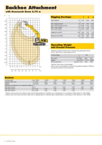
The Specification for DX225LCA section alone is worth the manual: it lists general dimensions and working ranges for every boom/arm/bucket combination Doosan offered on this model (5.2 m and 5.7 m booms with 2.0 m, 2.4 m, 2.9 m and 3.5 m arms), shipping and operating weights, major component weights, digging forces at power boost, fuel and hydraulic tank capacities, ground pressure ratings for each shoe width, and the DB58TIS engine’s rated power, torque and fuel consumption curves per the DIN 6270 standard. The Standard Torques section adds metric and U.S. fastener torque tables, hose clamp and split-flange torque values, and torque wrench extension guidance that applies across the whole machine.
Hydraulics and Electrical Coverage
Because the DX225LCA is a hydraulic excavator, the manual devotes its largest section to hydraulics: troubleshooting and adjustment procedures for the whole circuit, plus dedicated coverage of the accumulator, center joint, cylinders, swing motor, travel motor, gear pump, main control valve, axial piston pump, PTO server, remote and travel control valves, solenoid valve assembly, and the optional breaker EPPR valve, backed by the full hydraulic schematic for the DX225LC/DX225LCA. The Electrical System section covers the machine’s wiring logic alongside the complete electrical schematic for the DX225LCA, so electrical faults can be traced circuit by circuit rather than guessed at.
IMAGES PREVIEW
Why Technicians Choose This Doosan DX225LCA Shop Manual
With this Doosan DX225LCA Shop Manual you can diagnose hydraulic pressure and flow problems, rebuild or replace the swing motor, travel motor, main control valve or axial piston pump, service the swing bearing and reduction gear, correctly torque structural and hydraulic fasteners, trace electrical faults using the factory schematic, and work through counterweight, fuel tank, cabin, track assembly, boom, arm and bucket service using Doosan’s own procedures and specifications rather than guesswork. Using the correct torque values, clearances and hydraulic settings from this Shop Manual protects the machine from repeat failures and keeps repairs within the tolerances Doosan engineered for the DX225LCA. This is an instant PDF download – there is no physical item shipped. Once payment is confirmed you can save the DX225LCA Shop Manual to a laptop, tablet or phone, print any section you need in the shop, and reference it on any device without waiting on the mail.
What Our Customers Say
🌟 Related Products
Discover more professional manuals for your equipment

Hitachi ZX350LC-5B ZX350LCN-5B Technical Manual Operational Principle PDF Download

Sunward SWE18UF Crawler Excavator Operation & Maintenance Manual (July 2020)

Komatsu PC500LC-10M0 Hydraulic Excavator Shop Manual (S/N 95001 and up) - PDF Download


Reviews
There are no reviews yet.