★ TRUSTED BY 321,897+ PROFESSIONALS WORLDWIDE
🏢
Trusted Business
Verified & Licensed
🛡️
Virus Free Files
100% Safe Downloads
🔒
Secure Payment
SSL Protected
Instant Delivery
Available Immediately
Sale!

Doosan DX300LC-5 Excavator Operation and Maintenance Manual 2017 – Serial 20001 and Up

Original price was: $39.95.Current price is: $24.95.

Complete 506-page PDF Operation and Maintenance Manual for Doosan DX300LC-5 excavators from serial number 20001 and up. Covers operation, safety, maintenance, troubleshooting, specifications, and more.

Instant PDF Download
Available immediately
💾
Save to Your Device
Download & keep forever
🛡️
Antivirus Scanned
100% virus-free
🌍
Trusted Worldwide
175,000+ customers

Description

Doosan DX300LC-5 Excavator Operation and Maintenance Manual 2017

This Doosan DX300LC-5 Excavator Operation and Maintenance Manual 2017 – Serial 20001 and Up is the complete PDF manual for owners, operators, and technicians who need dependable factory-level guidance for the DX300LC-5 excavator. Covering machines from serial number 20001 and up, this 506-page document walks through safe operation, scheduled maintenance, system descriptions, troubleshooting, and machine specifications in clear, practical detail.

File Details

  • Manual type: Operation and Maintenance Manual
  • Brand: Doosan
  • Model: DX300LC-5 Excavator
  • Serial number coverage: 20001 and Up
  • Document number: 950106-01831ANA
  • Year: 2017
  • Language: English
  • Page count: 506 pages
  • File format: PDF

Chapters Covered

  • AEM Safety Manual (North America Only) – General safety information for operating and maintenance personnel
  • Federal and California Emission Control Systems – Fuel metering, air induction, EGR, catalyst, PCV, electronic control, and warranty coverage
  • Safety – Safety decals, general precautions, transportation, operation, maintenance, environment and circumstances
  • Operating Controls – Component locations, operator’s area, operational controls and panels, display monitor, user menu, heater and air conditioner control panel, stereo, electrical devices, seat adjustment, emergency stop switch, emergency exit glass breaking tool, convenience devices, access covers and doors, air gun and compressor
  • Operation – Operating a new excavator, starting and stopping engine, safety lever, travel, operating instructions, operating precautions, parking, towing, attachments, hydraulic attachments, lifting objects, lifting with quick coupler, abnormal conditions, long-term storage, auto grease system
  • Inspection, Maintenance and Adjustment – Maintenance information, setup position, handling oil/fuel/DEF/coolant, electrical maintenance, recommended lubricants, fluid capacities, maintenance intervals from 10-hour daily through 12,000-hour service, air-conditioning, bolt and nut inspection, bucket, electrical system, engine cooling, fuel transfer pump, accumulator, track tension, hydraulic venting, special conditions
  • Transportation – Loading and unloading, lifting machine
  • Troubleshooting – Electrical system, engine, VGT, lubrication, hydraulic system, air compressor, swing system, travel system, cooling fan, hydraulic fan drive system
  • Specification – Standard specification, overall dimensions, disassembled parts, ground pressure, digging force, working range, rated lift capacity tables, approximate weight of workload materials
  • Index – Alphabetical reference to manual topics

Complete PDF Bookmark Tree

Complete Bookmarks

The complete bookmarks in the “Doosan DX300LC-5 Excavator Operation and Maintenance Manual 2017 – Serial 20001 and Up” are as follows:

DX300LC-5p. 1
Table of Contentsp. 3
Forewordp. 7
Intended Usep. 7
Engine and Emission Control System Maintenancep. 7
Machine Capacityp. 8
Attachmentsp. 8
Product Identification Number (PIN)p. 9
Component Serial Numbersp. 9
Engine Identificationp. 10
Engine Data Platep. 10
Your Machine Serial Numbersp. 10
Safety Messagesp. 10
Signal Wordsp. 11
Other Signal Wordsp. 11
AEM Safety Manual (North America Only)p. 12
Federal and California Emission Control Systemsp. 13
Limited Warranty for Non-road Engines (CI) (FDICL05.8LEA (DL08P))p. 13
Owner’s Warranty Rights and Obligationsp. 13
Manufacturer's Warranty Coveragep. 14
Owner’s Warranty Responsibilitiesp. 14
Safetyp. 15
Safety Decalsp. 16
Safety Decals With Textp. 16
Safety Decals Without Text (No-Text)p. 17
Information and Location for Safety Decalsp. 18
Information and Location for Safety Decals (Continued)p. 19
1. General Hazard (950205-03804)p. 20
2. Warning Tag – "Do Not Operate" (950205-03802)p. 21
3. Keep Bystanders Away (950205-03803)p. 21
4. Hot Pressurized Fluid (950205-03781)p. 21
5. Entanglement in Rotating Parts (950205-03791)p. 21
6. Rotating Fan (950205-03788)p. 22
7. Battery Explosion (950205-03785)p. 22
8. Battery Disconnection (950205-03784)p. 22
9. Flying Debris or Objects (950205-03866)p. 23
10. Crush Hazard (950205-03805)p. 23
11. Pressurized Gas and Fluid (950205-03782)p. 23
12. Fall Hazard (950205-03783)p. 24
13. Hot Surface (950205-03777)p. 24
14. Emergency Exit (950205-03810)p. 24
15. ISO Control Pattern (950205-03860)p. 25
BHL Control Pattern (US Only) (950205-03868)p. 25
16. Impact Hazard (950205-03963)p. 25
17. Ultra Low Sulfur Diesel Fuel (950205-03863, 950205-03864)p. 26
18. ROPS Warning (950205-03861)p. 26
19. Falling Object (950205-03786)p. 27
20. Hydraulic Oil Check (950205-06281, 950205-03965, 950205-06282)p. 28
21. Hydraulic Breaker (950205-03964)p. 29
22. Lift/Tie down (950205-03815)p. 29
23. Tie down (950205-03816)p. 29
24. Electric Welding Attention (950212-02440)p. 29
25. Do Not Lift (950205-03570)p. 30
26. DEF (AdBlue) (950205-01489A)p. 30
Generalp. 31
Safe Operation is Operator's Responsibilityp. 31
Know Your Machinep. 31
Proper Work Tools and Attachmentsp. 32
Pressurized Fluidsp. 32
Flying or Falling Objectsp. 33
Personal Protective Equipment (PPE)p. 34
Correction of Machine Problemsp. 34
Crushing and Cuttingp. 34
Hot Coolant and Oils – Burn Preventionp. 35
Fire and Explosion Preventionp. 36
Maintenancep. 36
Operationp. 36
Electricalp. 37
Hydraulic Systemp. 37
Fuelingp. 38
Never Use Ether Starting Aidsp. 38
Welding and Grindingp. 38
If a Fire Occursp. 39
Fire Extinguisher and First-aid Kit (Emergency Medical Kit)p. 39
Electrical System and Electrical Shockp. 40
Roll-over Protective Structure (ROPS)p. 40
ROPS Certificationp. 41
Protecting Cabin from Flying or Falling Objects (Optional)p. 42
Emergency Exit from Operator's Stationp. 43
Transportationp. 44
Obey State and Local Over-the-Road Regulationsp. 44
Loading and Unloadingp. 44
Transporting Machinep. 45
Operationp. 46
Before Engine Startingp. 46
Machine Conditionp. 46
Work Sitep. 47
Mounting/Dismountingp. 48
Cleaningp. 49
Operator Stationp. 49
Seat Beltp. 50
Visibility Informationp. 51
Work Site Rulesp. 51
Boost Starting or Charging Engine Batteriesp. 52
Starting Enginep. 53
Swinging or Travelingp. 54
Lifting and Diggingp. 56
Operation on Slopesp. 57
Towingp. 58
Attachmentp. 59
Equipment Lowering with Engine Stoppedp. 59
Engine Stopp. 60
Parking Machinep. 60
Preservation/Storing Machinep. 61
Check After Long-term Parkingp. 62
Maintenancep. 63
Warning Tagp. 65
Cleaningp. 66
Proper Tools and Clothingp. 66
Disassembling Precautionsp. 66
Use of Lightingp. 66
Fire and Explosion Preventionp. 67
Burn Preventionp. 68
Rubber That Contains Fluoridesp. 69
Rubber and Plasticsp. 70
Waste Hazardous to the Environmentp. 70
Check List After Firep. 70
Welding Repairsp. 71
Preparation for Electrical Welding On Body Structurep. 72
Warning for Counterweight and Front Attachment Removalp. 72
Lock Inspection Coversp. 73
Working on Machinep. 73
Accumulatorp. 74
Compressed Airp. 74
Track Tension Adjustmentsp. 75
Supports and Blocking for Work Equipmentp. 75
High-pressure Lines, Tubes and Hosesp. 76
Batteryp. 77
Battery Hazard Preventionp. 77
Environment and Circumstancesp. 79
Work Site Areas Requiring Extra Cautionp. 79
Digging Under an Overhangp. 79
Deep Diggingp. 79
Drop-off or Edgep. 80
Poor Visibilityp. 80
Loose or Soft Groundp. 80
High-voltage Cablesp. 81
Underground Operationp. 82
Working in Waterp. 82
Working in Contaminated Environmentp. 82
Operation in Extreme Conditionsp. 83
Operation In Extreme Coldp. 83
Operation in Extreme Heatp. 84
Operation In Dusty and Sandy Areasp. 85
Operation in Rainy or Humid Conditionsp. 86
Operation in Saltwater Areasp. 86
Operation at High Altitudesp. 87
Operation During Electrical Stormsp. 87
Exhaust Ventilationp. 87
Ventilation for Enclosed Areap. 87
Asbestos Informationp. 88
Silica Dust Informationp. 88
Disposal of Hazardous Materialsp. 89
Soundp. 89
Vibration Informationp. 90
Hand/Arm Vibration Levelp. 90
Whole Body Vibration Levelp. 90
Guidelines for Use and Working Conditions of Earth-moving Machinery to Reduce Vibration Levels (ISO/TR 25398 Annex E)p. 90
Operating Controlsp. 93
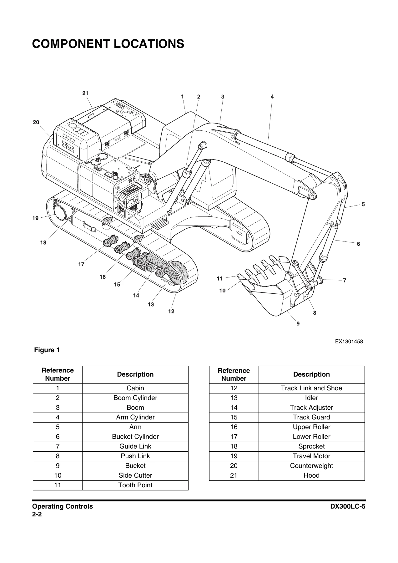
Component Locationsp. 94
Operator's Areap. 98
Operational Controls and Panelsp. 100
1. Starter Switchp. 102
2. Heater and Air Conditioner Control Panelp. 103
3. Power Socket for 12 Voltp. 103
4. Cigarette Lighterp. 103
5. Smart Power Control Switchp. 104
6. Engine Speed Control Dialp. 104
7. Travel Speed Selector Switchp. 104
8. Light Switchp. 105
9. Intelligent Floating Boom Switch (Optional)p. 105
10. Cabin Work Light Switch (Optional)p. 105
11. Audio Control Panelp. 106
12. Wiper Control Panelp. 107
13. Quick Coupler Switch (Optional)p. 108
14. Air Compressor Switch (Optional)p. 109
15. Warning Light Switch (Optional)p. 109
16. Lower Wiper Switch (Optional)p. 109
17. Travel/Swing Alarm Switch (Optional)p. 110
18. Overload Warning Switch (Optional)p. 110
19. Power Socket for 12 Volt (Optional)p. 111
20. Horn Button (Left-hand Work Lever)p. 111
21. Breaker/Booster Button (Right-hand Work Lever)p. 111
22. Rotating Switchp. 112
23. Shear Switchp. 112
24. Display Monitorp. 113
25. Photo Sensorp. 113
26. Safety Leverp. 113
27. Auxiliary Mode Switchp. 113
28. Hour Meterp. 114
29. DeSOx Switchp. 114
30. One Touch Deceleration Buttonp. 115
31. Intelligent Floating Boom Temporary Reset Buttonp. 115
32. Selector Switch Control Panelp. 115
33. Jack Assemblyp. 117
34. Micro Phonep. 118
Display Monitorp. 119
Functional Checkp. 119
Password Activatedp. 120
1. Fuel Gaugep. 120
2. DEF (AdBlue) Level Gaugep. 120
3. Engine Coolant Temperature Gaugep. 121
4. Hydraulic Oil Temperature Gaugep. 121
5. Multifunction Gauge and Graphic Information Areap. 122
6. ECO Gaugep. 123
7. Trip Meterp. 123
8. Digital Clockp. 124
9. Display Warning Symbolsp. 124
10. Warning Lightp. 134
11. Function Buttonsp. 135
12. Mode Selector Buttonsp. 137
13. Selector Function Displayp. 138
14. Jog Switchp. 139
15. Camera Mode Selector/ESC Buttonp. 139
16. Multimedia Selector Buttonp. 139
Launch Menup. 140
Warning Pop-up Windowp. 143
Warning Pop-up Windows Listp. 145
User Menup. 146
User Menu – Access and Escape Methodsp. 146
Access Methodp. 146
Escape Methodp. 146
User Menup. 146
Switch Operation Indicationp. 185
Heater and Air Conditioner Control Panelp. 188
Location of Controls and Ventsp. 188
Control Panelp. 189
1. Automatic Temperature Control Buttonp. 189
2. Off Buttonp. 190
3. Temperature Control Buttonp. 190
4. Temperature Unit Selector Buttonp. 190
5. Mode Selector Buttonp. 190
6. Air Inlet Selector Buttonp. 192
7. Fan Speed Selector Buttonsp. 192
8. Air Conditioner Buttonp. 192
9. Defroster Buttonp. 193
10. LCD Displayp. 193
Memory Functionp. 193
Additional Operating Instructionsp. 193
Stereop. 194
Stereop. 194
Miscellaneous Electrical Devicesp. 195
Cabin Lightp. 195
Pilot Cutoff Switchp. 195
Circuit Breaker (80 A)p. 195
Circuit Breaker (30 A)p. 196
Fuse Boxesp. 196
Seat Adjustmentp. 197
1. Forward/Backward Adjustmentp. 197
2. Adjusting Height of Seat and Depth of Cushionp. 197
Forward Tiltp. 197
Cushion Slidep. 197
Seat Heightp. 197
3. Reclining Position Adjustmentp. 198
4. Lumbar Support Adjustmentp. 198
5. Headrestp. 198
6. Seat Beltp. 198
Seat Belt Locking and Unlockingp. 199
7. Left and Right Control Stand Adjustmentp. 199
8. Left and Right Control Stand Height Adjustmentp. 199
9. Adjusting Height/Angle of Armrestp. 200
10. Heating Operator's Seatp. 200
Engine Emergency Stop Switchp. 201
Emergency Exit Glass Breaking Toolp. 201
Miscellaneous Convenience Devicesp. 202
Ceiling Coverp. 202
Opening Ceiling Coverp. 202
Closing Ceiling Coverp. 202
Front Windowsp. 203
Front Upper Windowp. 203
Front Bottom Windowp. 204
Door Side Latchp. 205
Cabin Storage Compartmentsp. 206
Sunglasses Casep. 206
Sun Visorp. 207
Front Window Visorp. 207
Ceiling Window Visorp. 207
Cup Holderp. 208
Miscellaneous Access Covers and Doorsp. 209
Side Doorp. 209
Storage Box Doorp. 209
Openingp. 209
Closingp. 209
Radiator Coverp. 210
Engine Coverp. 210
Air Gun and Compressor (Optional)p. 211
Air Gun (Optional)p. 211
How to Use Air Compressorp. 211
How to Connect Air Gunp. 213
Operationp. 215
To Operate a New Excavatorp. 215
Starting and Stopping Enginep. 216
Inspection Before Starting Enginep. 216
Walk Around Checksp. 216
Checks Before Starting Enginep. 218
Operational Checks Before Starting Enginep. 219
Engine Startp. 220
Cold Weather Startingp. 222
Engine Pre-heaterp. 222
Engine Coolant Heater (Optional)p. 225
Overviewp. 225
Operating and Settingp. 226
Plug Heater (Optional)p. 235
Starting Engine with a Booster Cablep. 236
Connecting Booster Batteriesp. 236
Disconnecting Booster Batteriesp. 237
Hydraulic System Warm-upp. 237
Hydraulic System Warm-up – Cold Weatherp. 238
Stopping Enginep. 240
Checks and Maintenance After Stopping Enginep. 241
Safety Leverp. 241
Travelp. 242
Automatic Travel Speed Controlp. 242
Travel Control Lever Operationp. 243
General Travel Instructionsp. 244
Straight Travel Pedal (Optional)p. 246
Operatingp. 247
Locking Pedalp. 247
Operating Instructionsp. 248
Engine Speed Controlp. 248
Emission Control Systemp. 248
Reaction at Low Reductant Levelp. 248
Reaction to Faults in SCR System – EPAp. 249
Reaction to Blocked EGR Valve and Malfunction of the Monitoring – EUp. 249
Reaction to Interruption of Dosing and Reagent Quality – EUp. 250
DeSOxp. 251
Active DeSOxp. 252
Manual (Forced) DeSOxp. 253
Mode Selectionp. 254
Power Modep. 254
Work Modep. 255
Auto Idle Modep. 255
Boost Modep. 256
Work Levers (Joysticks) (ISO Pattern)p. 257
Left-hand Work Lever (Joystick) (Figure 96 and Figure 97)p. 257
Right-hand Work Lever (Joystick) (Figure 96 and Figure 99)p. 257
Change Machine Control Pattern By Selector Valve (If Equipped)p. 258
Work Levers (Joysticks) (BHL Pattern)p. 259
Left-hand Work Lever (Joystick) (Figure 100 and Figure 102)p. 259
Right-hand Work Lever (Joystick) (Figure 100 and Figure 103)p. 259
Intelligent Floating Boom Control (Optional)p. 260
Intelligent Floating Boom Modep. 260
Operating a Breakerp. 260
Truck Loadingp. 261
Two-Piece Boom (Optional)p. 262
Smart Power Control (SPC)p. 262
Operating Precautionsp. 263
Working in Waterp. 269
Escaping From Mudp. 269
Track On One Side Stuckp. 269
Tracks On Both Sides Stuckp. 269
Parking Excavatorp. 270
Towing Procedurep. 271
Attachmentsp. 272
Bucket Replacement and Reversalp. 272
Replacementp. 272
Reversal (If Applicable)p. 274
Hydraulic Attachments (Optional)p. 275
Breaker Operationp. 275
Selection of Hydraulic Breakerp. 275
Hydraulic Hoses and Tubing for Breakerp. 275
Breaker Operating Precautionsp. 276
To Activate Breakerp. 278
Hydraulic Oil and Filter Service Intervalsp. 279
Shear Operationp. 280
To Activate Shearp. 281
One-Way/Two-Way Valve Operationp. 283
Activating Shear with Pedal Valvep. 283
Activating Breaker with Pedal Valvep. 283
Stopper Positionsp. 283
Rotating Operationp. 284
Quick Coupler Operationp. 285
To Engage Attachmentp. 285
To Release Attachmentp. 289
Lifting Objectsp. 290
Lifting Unknown Weightp. 291
Lifting Known Weightp. 291
Pick and Carryp. 291
Lifting Objects with Quick Couplerp. 292
Operation Under Abnormal Conditionsp. 294
Operation In Extreme Coldp. 294
Operation in Extreme Heatp. 295
Operation In Dusty and Sandy Areasp. 297
Operation in Rainy or Humid Conditionsp. 297
Operation in Saltwater Areasp. 298
Operation at High Altitudesp. 298
Operation During Electrical Stormsp. 298
Equipment Lowering with Engine Stoppedp. 299
Machine without a Boom Lock Valvep. 299
Machine with a Boom Lock Valvep. 301
Long Term Storagep. 302
Before Storagep. 302
During Storagep. 303
After Storagep. 303
Auto Grease System (Optional)p. 304
Overviewp. 304
Locationp. 306
Lubricantsp. 307
Approved Lubricantsp. 307
Lubricant Hazardsp. 308
Lubricant Fillingp. 308
Filler Couplingp. 309
Filling Cylinder (Optional)p. 309
Cleaningp. 310
Pump Display and Control Elements of Control Screenp. 311
Display and Control Elementsp. 311
Three-digit LED Displayp. 312
LED Displayp. 314
Push Button Operationp. 314
Pump Display Modep. 315
Pump Programmingp. 317
Start Programming Modep. 317
Change Lubrication Interval Timesp. 317
Configure System Monitoringp. 318
Change Operating Modesp. 319
Change Access Codep. 320
Programming Rangesp. 321
Display Rangesp. 321
Maintenancep. 321
General Informationp. 323
Troubleshootingp. 324
Operational Malfunctionsp. 324
Recording Fault Timesp. 326
Maintenance and Repairp. 326
Malfunctions on Pump Unit in Progressive Systemp. 327
Malfunctions on Pump Unitsp. 328
Inspection, Maintenance and Adjustmentp. 331
Maintenance Informationp. 331
Operational Hour Meter Readingp. 331
DOOSAN Genuine Replacement Partsp. 331
DOOSAN Genuine Lubricantsp. 331
Windshield Washer Fluidp. 331
Fresh and Clean Lubricantsp. 331
Check Drained Oil and Used Filterp. 331
Fuel Strainerp. 331
Welding Instructionsp. 332
Do Not Drop Things Inside Machinep. 332
Dusty Work Sitep. 332
Avoid Mixing Lubricantsp. 332
Locking Inspection Coversp. 332
Hydraulic System – Air Bleedingp. 333
Hydraulic Hose Installationp. 333
Checks After Inspection and Maintenance Worksp. 333
Safety Precautionsp. 334
Machine Setup Position for Maintenancep. 335
Maintenance Handling Accessp. 337
Entering/Leaving/Climbing On Machinep. 337
Handling Oil, Fuel, DEF (AdBlue), Coolantp. 338
Oilp. 338
Fuelp. 338
DEF (AdBlue)p. 340
Engine Oilp. 341
Greasep. 341
Coolant and Water for Dilutionp. 341
Filtersp. 342
Electrical System Maintenancep. 343
Recommend Fuel, Coolant, and Lubricantp. 344
Lubricationp. 344
Symbols for "Lubrication and Service Chart"p. 345
Lubrication and Service Chartp. 346
Fluid Capacitiesp. 349
Table of Recommended Lubricantsp. 350
Maintenance Intervalsp. 352
10 Hour / Daily Servicep. 355
Grease Boom, Arm and Front Attachment Pins (for first 100 hours)p. 355
Check Engine Oil Levelp. 355
Check for Leaks in Hydraulic Systemp. 355
Check Level of Hydraulic Oil Tankp. 356
Check for Leaks in Fuel Systemp. 357
Check Fuel Levelp. 357
Check DEF (AdBlue) Tankp. 359
Check Water Separator and Pre Fuel Filter (Fuel Prefilter) and Drain Water As Requiredp. 360
Check Oil Level of Swing Reduction Gearp. 361
Clean Dust Net in Front of Oil Cooler and Radiatorp. 362
Oil Coolerp. 362
Radiatorp. 362
Check Cooling System and Refill As Requiredp. 363
Check Level of Window Washer Liquidp. 363
Inspect Bucket Teeth and Side Cutters for Signs of Wearp. 364
Inspect Cooling Fan Bladep. 364
Check Air Intake System and Emission Control System Componentsp. 365
Inspect Seat Belt for Proper Operationp. 365
Inspect Rear/Side View Camera for Proper Operation (If Equipped)p. 365
Inspect Mirrors for Damage and Adjust and Clean as Requiredp. 366
Inspect Structure for Cracks and Faulty Weldsp. 366
Check Operation of All Switches and Travel Alarm (If Equipped)p. 366
Check the Operation of Pilot Cutoff Switchp. 366
Inspection and Maintenance of the Pilot Cutoff Switchp. 366
Check Operation of All Exterior Lights, Horn and Control Console Indicator and Display Monitorp. 367
Start Engine, Check Starting Ability, and Observe Exhaust Color at Start-up and at Normal Operating Temperature. Listen for Any Abnormal Sounds.p. 367
Check Operation of All Controls and Linkagesp. 368
50 Hour / Weekly Servicep. 369
Perform All Daily Service Checksp. 369
Grease Arm and Bucket Joint Pinsp. 369
Grease Swing Bearingp. 370
Drain Water and Sediment from Fuel Tankp. 371
Check Air Compressor and Drain Water as Requiredp. 371
Check Engine Fan Belt for Cracks and Wear (After First 50 Hours)p. 372
Inspect the Track Assemblies for Proper Tension and Loose, Worn or Damaged Parts (Links, Shoes, Rollers, Idlers)p. 372
250 Hour / Monthly Servicep. 373
Perform All Daily and 50 Hour Service Checksp. 373
Grease Boom and Arm Joint Pinsp. 373
Check Engine Fan and Alternator Belts Wearp. 375
Change Breaker Filter (Optional)p. 376
Check Oil Bath Precleaner (Optional)p. 377
Clean Oil Bath Precleaner (Optional)p. 377
Clean Air Compressor Filter (Optional)p. 379
Replace Hydraulic Oil Return Filter (After First 250 Hours)p. 380
Change Pilot Filter (After First 250 Hours)p. 380
Inspect Pins and Bushings of the Front End Attachments for Signs of Wearp. 380
Check Fluid Levels in Batteriesp. 380
Inspect for Any Loose or Missing Nuts and Boltsp. 380
Inspect Fuel System Hose Clampsp. 380
500 Hour / 3 Month Servicep. 381
Perform All Daily, 50 and 250 Hour Service Checksp. 381
Grease Swing Gear and Pinionp. 381
Change Engine Oil and Filterp. 382
Clean Air-conditioning Outer Filterp. 384
Check and Clean Air-conditioning Inner Filterp. 385
Clean Radiator, Oil Cooler, Intercooler, Fuel Cooler and Air Conditioner Condenser Coresp. 386
Clean Outer Filter of Air Cleanerp. 387
Change of Water Separator and Pre Fuel Filter (Fuel Prefilter)p. 389
Change Main Fuel Filterp. 390
Bleeding Fuel Systemp. 390
Change Air Compressor Filter (Optional)p. 391
Check Oil Level in Travel Reduction Gear (One on Each Side of Unit)p. 392
Change Oil in Travel Reduction Gear (One on Each Side of Unit) (After First 500 Hours)p. 392
Change Oil in Swing Reduction Gear (Drain and Refill After First 500 Hours)p. 392
1,000 Hour / 6 Month Servicep. 393
Perform All Daily, 50, 250 and 500 Hour Service Checksp. 393
Grease Swing Reduction Gearp. 393
Change Hydraulic Oil Tank Breather Filterp. 393
Replace Hydraulic Oil Return Filterp. 394
Change Pilot Filterp. 395
Change Oil in Travel Reduction Gear (One on Each Side of Unit)p. 396
Change Oil in Swing Reduction Gearp. 397
Change Air-conditioning Outer Filterp. 398
Change Air-conditioning Inner Filterp. 399
Check Air Conditioner Refrigerantp. 400
Change Fuel Cap Filterp. 401
Check and Adjust Engine**p. 402
2,000 Hour / Yearly Servicep. 403
Perform All Daily, 50, 250, 500 and 1,000 Hour Service Checksp. 403
Replace Outer and Inner Air Cleaner Filtersp. 403
Change Radiator Coolantp. 405
Hydraulic Oil Exchange and Suction Strainer Cleaningp. 407
Check Alternator and Starter**p. 409
Check All Rubber Antivibration Shock Mountsp. 409
Perform and Record Results of Cycle Time Testsp. 409
Inspect Machine to Check for Cracked or Broken Welds or other Structural Damagep. 409
Check, Adjust Valve Clearance**p. 409
Check Head Bolt Torquesp. 409
4,000 Hour / Biennial Servicep. 410
Major Parts – Periodic Replacementp. 410
4,500 Hour / Biennial Servicep. 411
Change DEF (AdBlue) Filterp. 411
12,000 Hour / 6 Year Servicep. 414
Hose In-service Lifetime Limit (European Standard ISO 8331 and EN982 (CEN))p. 414
Air-conditioning Systemp. 415
Check Control Panelp. 415
Check Air Conditioner Hosesp. 415
Check Condenserp. 415
Check Magnetic Clutchp. 415
Bolt and Nut Inspectionp. 416
Bucketp. 425
Bucket Tooth Replacementp. 425
Bucket O-ring Replacementp. 426
Electrical Systemp. 427
Batteryp. 427
Batteries in Cold Weatherp. 427
Inspection of Battery Electrolyte Levelp. 428
Check Charging Statep. 428
Check Battery Terminalsp. 428
Battery Replacementp. 428
Fusesp. 429
Fuse Boxesp. 429
Fuse Identificationp. 430
Engine Cooling Systemp. 431
Generalp. 431
Types of Antifreezep. 432
Antifreeze Concentration Tablesp. 433
Table of Standards for Allowed Tap Waterp. 433
Fuel Transfer Pump (Optional)p. 434
Handling of Accumulatorp. 437
Track Tensionp. 438
Venting and Priming Hydraulic Systemp. 440
Main System Pumpp. 440
Hydraulic Cylindersp. 440
Swing Motorp. 441
Travel Motorp. 441
General Ventingp. 441
Maintenance in Special Conditionsp. 442
Transportationp. 443
Loading and Unloadingp. 444
Warning for Counterweight and Front Attachment Removalp. 444
Counterweightp. 444
Removalp. 445
Installationp. 446
Lifting Machinep. 451
Troubleshootingp. 453
Electrical Systemp. 453
Enginep. 454
Variable Geometry turbocharger (VGT)p. 458
Lubrication Systemp. 459
Hydraulic Systemp. 460
Air Compressor (Optional)p. 461
Swing Systemp. 462
Travel Systemp. 462
Cooling Fanp. 462
Hydraulic Fan Drive Systemp. 463
Specificationp. 465
Standard Specificationp. 465
Overall Dimensionsp. 466
One – Piece Boomp. 466
Two – Piece Boomp. 467
Disassembled Parts, Dimension and Weightp. 468
Componentsp. 468
Boomp. 468
Armp. 469
Counterweightp. 470
Ground Pressurep. 470
Digging Forcep. 471
Working Rangep. 472
One – Piece Boomp. 472
Two – Piece Boomp. 474
Excavator Rated Lift Capacity Tablesp. 476
Approximate Weight of Workload Materialsp. 496
Indexp. 499

This Doosan DX300LC-5 Operation and Maintenance Manual 2017 gives a technician the structure to work through the machine systematically. The early safety chapters establish the correct procedures for leaving the operator’s seat, locking out controls, and working around high-pressure hydraulic systems. The operating controls section explains the display monitor, user menu, heater and air conditioner panel, and the various switches and levers that control the DX300LC-5. The operation chapters cover travel, digging, lifting, attachment use, and abnormal conditions such as extreme cold, extreme heat, dusty areas, and working in water. The maintenance chapters are especially detailed, with daily, weekly, monthly, yearly, and biennial service tasks, fluid capacities, recommended lubricants, and component-specific inspection steps. The troubleshooting section helps diagnose electrical, engine, hydraulic, swing, travel, and cooling fan issues. The specification section provides dimensions, digging forces, working ranges, and rated lift capacity tables for the DX300LC-5.

Safety and Compliance Information

The manual includes extensive safety content, including signal words, safety decals, roll-over protective structure information, seat belt inspection, pressurized fluid warnings, fire and explosion prevention, battery hazards, and track tension adjustment precautions. It also covers federal and California emission control system requirements and owner warranty responsibilities. This is important reference material for anyone who needs to understand the required maintenance and safe operation of the DX300LC-5.

Maintenance and Troubleshooting Coverage

For the DX300LC-5, the maintenance section details grease points on the boom, arm, bucket, swing bearing, and front attachment pins. It explains how to check engine oil, hydraulic oil, coolant, fuel, DEF (AdBlue), swing reduction gear oil, travel reduction gear oil, and battery electrolyte. Service intervals are laid out from 10-hour daily checks through 50-hour weekly, 250-hour monthly, 500-hour quarterly, 1,000-hour six-month, 2,000-hour yearly, 4,000-hour biennial, 4,500-hour biennial DEF filter service, and 12,000-hour hose replacement guidance. Troubleshooting tables cover common problems such as a starter that does not operate, engine that cranks but does not start, low power, overheating, hydraulic controls that do not function, swing and travel issues, and cooling fan faults.

IMAGES PREVIEW

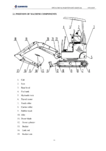
Doosan DX300LC-5 Excavator Operation and Maintenance Manual 2017 - Serial 20001 and Up — PDF page 1 preview
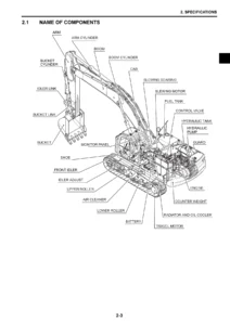
Doosan DX300LC-5 Excavator Operation and Maintenance Manual 2017 - Serial 20001 and Up — PDF page 94 preview
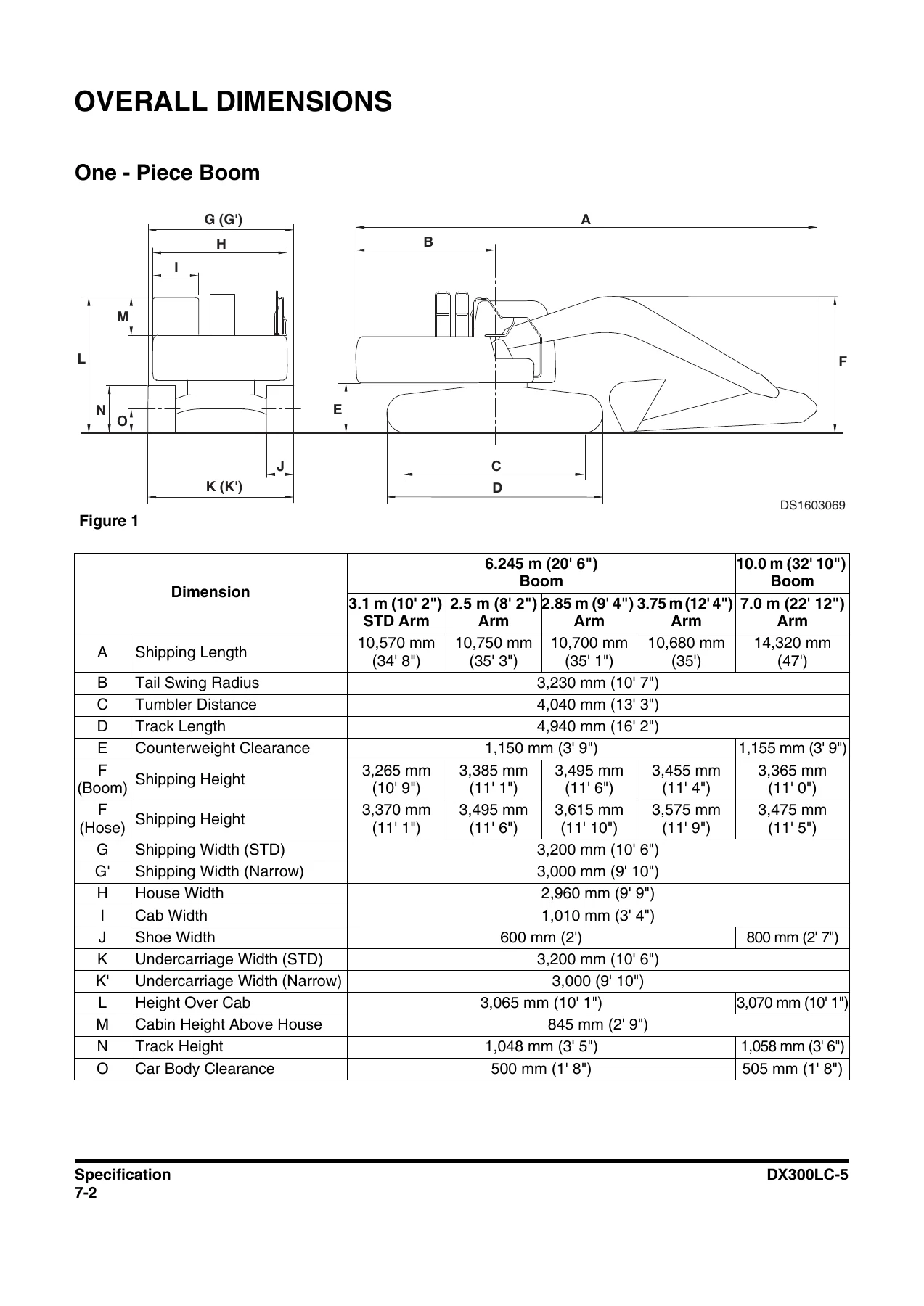
Doosan DX300LC-5 Excavator Operation and Maintenance Manual 2017 - Serial 20001 and Up — PDF page 466 preview

Specifications and Lift Capacity

The specification section gives the DX300LC-5 standard configuration data, including the DL08P engine, hydraulic pump details, digging capability, swing speed, travel speed, traction force, gradeability, ground pressure, track shoe width, and roller quantities. It also includes overall dimensions for one-piece and two-piece boom configurations, disassembled component weights, digging forces in SAE and ISO ratings, working range diagrams, and rated lift capacity tables. These tables are essential when the excavator is used for lifting objects, as they show how capacity changes with reach, boom length, arm length, counterweight, and track width.

Why This Doosan DX300LC-5 Manual Matters

Having the correct Doosan DX300LC-5 Excavator Operation and Maintenance Manual 2017 – Serial 20001 and Up means you can perform daily checks, scheduled maintenance, and troubleshooting with the exact procedures and values intended for this machine. It helps avoid guesswork when checking hydraulic pressures, adjusting track tension, servicing the cooling system, replacing filters, or diagnosing an electrical fault. The manual also supports safe operation by reinforcing lockout procedures, seat belt use, lifting limits, and hazard awareness. For a 506-page document, this PDF provides deep coverage that is useful for both routine ownership and more involved repair planning.

Instant PDF Access

This Doosan DX300LC-5 Operation and Maintenance Manual is delivered as an instant PDF download after purchase. There is no shipping and no waiting for a physical book. You can view it on a computer, tablet, or smartphone, print only the pages you need for the shop, and keep the file on hand for quick reference. Whether you are servicing a DX300LC-5 in the field, maintaining a fleet, or preparing for a repair, this PDF manual gives you the information in a convenient, portable format.
Reviews

There are no reviews yet.

Be the first to review “Doosan DX300LC-5 Excavator Operation and Maintenance Manual 2017 – Serial 20001 and Up”

What Our Customers Say

★★★★★ Live reviews from customers
Loading customer reviews...
0
    0
    Your Cart
    Your cart is emptyReturn to Shop
    🛒
    Recently Purchased
    🕒 verified order