★ TRUSTED BY 321,897+ PROFESSIONALS WORLDWIDE
🏢
Trusted Business
Verified & Licensed
🛡️
Virus Free Files
100% Safe Downloads
🔒
Secure Payment
SSL Protected
Instant Delivery
Available Immediately
Sale!

Hitachi EX200-2 EX200LC-2 Technical and Workshop Manual – Hydraulic Excavator PDF

Original price was: $41.95.Current price is: $25.95.

Combined technical and workshop manuals for the Hitachi EX200-2 and EX200LC-2 hydraulic excavators, covering machine systems, performance testing, troubleshooting, component overhaul, and the Isuzu 6BD1T engine family.

Instant PDF Download
Available immediately
💾
Save to Your Device
Download & keep forever
🛡️
Antivirus Scanned
100% virus-free
🌍
Trusted Worldwide
175,000+ customers

Description

Hitachi EX200-2 EX200LC-2 Technical and Workshop Manual – Hydraulic Excavator PDF

This download brings together the Hitachi EX200-2 technical manual and the matching EX200-2 workshop manual in one PDF. The first half explains how the machine is built and how the hydraulic, electrical, and travel systems work. The second half walks through removal, disassembly, inspection, assembly, and maintenance standards for the same components, plus a full engine-and-accessory workshop section for the Isuzu industrial diesel family used on this model. Serial applicability shown in the weight tables starts at 147-60001- for both the standard EX200-2 and long-undercarriage EX200LC-2.

File Details

  • Manual type: Technical Manual and Workshop Manual (combined)
  • Brand / models: Hitachi EX200-2, EX200LC-2
  • Language: English
  • Page count: 1151
  • File format: PDF
  • Internal numbering: T-series technical pages and W-series workshop pages (examples: 107T-01-01, 107W-01-01)

Machines and Configuration Shown in the Manual

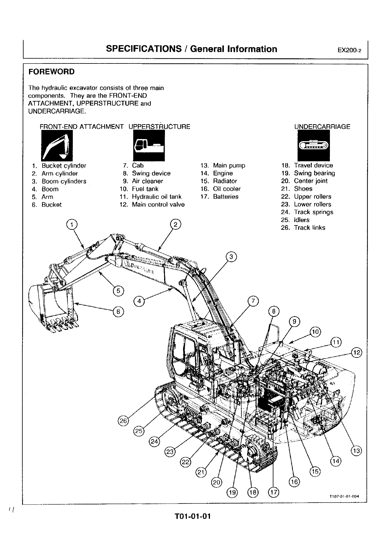
The specifications group treats the excavator as three assemblies: front-end attachment, upperstructure, and undercarriage. Standard specification data is written around a backhoe with a 2.91 m (9 ft 7 in.) arm and a 0.8 m³ PCSA/SAE (0.7 m³ CECE/JIS) bucket. Operating weight is listed as 18 500 kg (40 800 lb) for the EX200-2 and 19 000 kg (41 900 lb) for the EX200LC-2. Basic machine weight is 15 000 kg and 15 500 kg respectively. The engine line in the machine specification table is ISUZU 6BD1T, 99 kW (135 ps) at 2050 min⁻¹ (rpm).

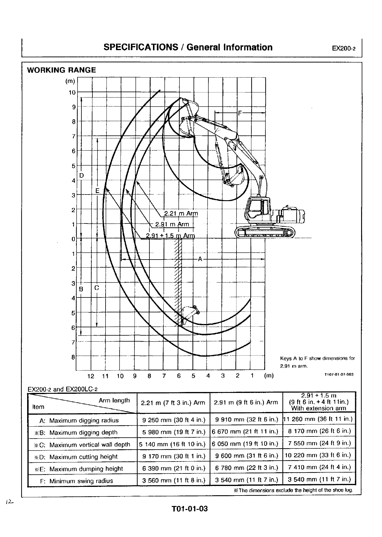
Working-range charts cover three arm lengths used on both models: 2.21 m, 2.91 m, and 2.91 m plus a 1.5 m extension. With the 2.91 m arm, maximum digging radius is 9 910 mm and maximum digging depth is 6 670 mm (shoe-lug height excluded). Lifting-capacity tables follow SAE J1097 and are given separately for EX200-2 and EX200LC-2 with the 5.68 m boom, 2.91 m arm, 3900 kg counterweight, 0.8 m³ bucket, and 600 mm shoes. Travel speeds are 2.5 / 3.5 / 5.5 km/h. Swing speed is 11 min⁻¹. Gradeability is 35° (tan θ = 0.70). Ground pressure with 600 mm grouser shoes is 0.41 bar on EX200-2 and 0.39 bar on EX200LC-2.

Service refill figures include a 310 liter fuel tank, 21 liters of engine coolant, 25 liters of engine oil, 8.2 liters in the swing reduction gears, 5.5 liters in each travel reduction gear, 200 liters in the hydraulic system, and 130 liters in the hydraulic oil tank. Recommended fuel is ASTM D 975 No. 2D diesel; kerosene is not permitted. Grease, engine oil, gear oil, hydraulic oil, and coolant recommendations sit in their own group with service-hour intervals from 8 through 2000 hours.

Chapters Covered

Technical Manual

  • Section 01 Specifications — general information, working range, lifting capacities, refill capacities, transportation dimensions and weights, fuels and lubricants, interchangeability with EX200 and attachment installation notes
  • Section 02 Upperstructure — layout; hydraulic oil and fuel tanks; main pump, regulator, and gear pump; swing motor, brake valve, parking brake, swing dampener valve, and reduction device; main and pilot piping; three-spool and four-spool control valve, system pressure regulator, surge and overload relief, variable pressure compensated valve, shuttle and holding valves; pilot valve; lock valve
  • Section 03 Undercarriage — component location, swing bearing, center joint, travel reduction device, travel motor, travel brake valve, parking brake, track adjuster
  • Section 04 Electrical System — component location, monitor and switch panels, relays, wiring diagram and connectors; engine control system and EC motor; monitor functions and check procedure; power, preheat, start, charging, accessory, auto-idle, and engine-stop circuits; fuse, fusible-link, A-sensor, and EC-sensor inspection
  • Section 05 Hydraulic System — main, suction, delivery, return, drain, and pilot circuits; load sensing, speed sensing, flow dividing, job-mode selector, 3-speed propel, swing parking brake, warm-up, and power-boost control; neutral, swing, arm-in, combined, and relief circuits
  • Section 06 Operational Performance Test — performance standards; engine speed and compression tests; travel, swing, cylinder cycle, drift, lever force/stroke, and combined-function checks; pilot, PC, PI, main-pump, regulator, overload-relief, flow, and motor-drain tests; Dr. EX basic performance checks
  • Section 07 Troubleshooting — diagnosing procedure and Dr. EX start-up/self-diagnosis; connector maps; EC- and PVC-related fault codes; machine-malfunction cause charts; monitor, gauge, and level-indicator faults; harness continuity and circuit tests on the 24-volt system

Complete PDF Bookmark Tree

Complete Bookmarks

The complete bookmarks in the “Hitachi EX200-2 EX200LC-2 Technical and Workshop Manual – Hydraulic Excavator PDF” are as follows:

Back
INTRODUCTIONp. 1
SAFETYp. 3
TECHNICAL MANUAL EX200-2p. 14
SECTION 01p. 15
Group 01 General Informationp. 16
Forwordp. 16
Specificationsp. 17
Working Rangep. 18
Lifting Capacitiesp. 19
Service Refill Capacitiesp. 21
Group 02 Dimensions and Weightsp. 22
Transportationp. 22
Weightp. 23
Group 03 Fuels and Lubricantsp. 24
Fuelp. 24
Greasep. 25
Engine Oilp. 26
Gear Oilp. 27
Hydraulic Systemp. 28
Engine Coolantp. 29
Group 04 Interchangeabilityp. 31
Interchangeabilityp. 31
Installation of Attachmentsp. 32
SECTION 02 UPPERSTRUCTUREp. 33
Group 01 Layoutp. 35
Layout of Upperstructurep. 35
Group 02 Tanksp. 36
Hydraulic Oil Tankp. 36
Fuel Tankp. 36
Group 03 Pump Devicep. 37
Construction and Functionp. 37
Main Pumpp. 38
Regulatorp. 42
Gear Pumpp. 46
Group 04 Swing Devicep. 47
Construction and Functionp. 47
Swing Motorp. 48
Brake Valvep. 49
Parking Brakep. 52
Swing Dampener Valvep. 54
Swing Reduction Devicep. 58
Group 05 Pipingsp. 59
Construction and Functionp. 59
Main Pipingsp. 60
Pilot Pipingsp. 64
Group 06 Control Valvep. 68
Constructionp. 68
No.1 Valve (Three Spools Side)p. 69
No.2 Valve (Four Spools Side)p. 70
Main Relief Systemp. 71
Surge Relief Valvep. 72
Overload Relief Valve with Anti-Cavitation Featurep. 74
Variable Pressure Compensated Valvep. 75
Shuttle Valvep. 77
Holding Valvep. 78
Operation(Lever in Neutral)p. 79
Operation(Single)p. 80
Operation(Combined)p. 81
Hydraulic Pilot Warm Up Circuitp. 82
Auxiliary Spool Speed Adjustmentp. 83
Group 07 Pilot Valvep. 84
Construction and Functionp. 84
Pilot Valvep. 84
Shuttle Valvep. 93
Group 08 Lock Valvep. 94
Construction and Functionp. 94
Group 09 Shockless Valvep. 95
Construction and Functionp. 95
Group 10 Accumulatorp. 96
Constructionp. 96
Functionp. 97
Caoutions for Handlingp. 98
Group 11 Solenoid Valvep. 100
Construction and Functionp. 100
Pump Displacement Solenoid Valvep. 101
Solenoid Valve Assemblyp. 102
SECTION 03 UNDERCARRIAGEp. 106
Group 01 Component Locationp. 107
Component Locationp. 107
Group 02 Swing Bearingp. 108
Construction and Operationp. 108
Group 03 Center Jointp. 109
Construction and Operationp. 109
Group 04 Travel Devicep. 110
Construction and Operationp. 110
Travel Reduction Devicep. 111
Travel Motorp. 112
Travel Brake Valvep. 117
Parking Brakep. 121
Group 05 Adjusterp. 123
Construction and Operationp. 123
SECTION 04 ELECTRICAL SYSTEMp. 124
Group 01 Component Locationp. 125
Component Loationp. 125
Monitor and Switch Panelp. 127
Monitor Panelp. 128
Switch Panel (1)p. 129
Switch Panel (2)p. 130
Relaysp. 131
Electric Wiring Diagramp. 132
Connectorp. 133
Group 02 Engine Control Systemp. 148
Outline of Control Systemp. 148
Summary of Control Circuitp. 149
Outline of the Engine Contorl Systemp. 156
Operation of the Engine Contol Motorp. 157
Engine Control Circuitp. 158
Setting Engine Mode Speeds and Engine Speed Programingp. 159
Engine Stop Double Functionp. 160
Function of the Main Electrical Equipmentp. 161
Group 03 Monitorp. 169
Outline of the Monitorp. 169
Monitor Panelp. 170
Monitor Functionp. 171
Monitor Check Procedurep. 177
Group 04 Circuit Operationp. 178
Characteristics of the Electrical Systemp. 178
Power Circuitp. 179
Preheat Circuitp. 181
Engine Start Circuitp. 183
Changing Circuitp. 185
Operation of the Requlatorp. 187
Voltage Adjustmentp. 188
How to Troubleshoot Malfunction in the Circuitp. 189
Surge Voltage Prevention Circuitp. 191
Accessory Circuitp. 193
E.C. Motor Engine Stopp. 195
Stop Motor Engine Stopp. 197
Key Switch Engine Stopp. 198
Emergency Engine Stopp. 199
Auto Idle Functionp. 200
Group 05 Inspection and Maintenancep. 201
Precautions for Inspection and Maintenancep. 201
Fuse Continuity Testp. 202
Taking Apart Connectorsp. 203
Inspection and Replacement of Fusible Linksp. 205
Inspection and Adjustment of the A-sensorp. 206
Positioning the E.C. Sensorp. 207
SECTION 05 HYDRAULIC SYSTEMp. 208
Group 01 Generalp. 209
Generalp. 209
Main Circuitp. 210
Suction Circuit and Delivery Circuitp. 210
Return Circuitp. 211
Drain Circuitp. 212
System Pressure Regulate Controlp. 213
Pilot Circuitp. 214
Suction, Delivery and Return Circuitp. 215
Contorl Systemp. 216
Control System Layoutp. 216
Group 02 Control Systemp. 218
Pump Control Systemp. 218
Load Sensing Systemp. 218
Speed Sensing Systemp. 222
Valve Control Systemp. 224
Flow Dividing Control Systemp. 224
Job Mode Selector Systemp. 225
Travel Motor Control Systemp. 226
3-Speed Propel Controlp. 226
Other Control Systemp. 227
Warming-Up Contorlp. 227
Power Boost Systemp. 228
Group 03 Control Circuitp. 231
Main Hydraulic Circuitp. 231
Neutral Circuitp. 231
Single Operationp. 232
Arm in Operationp. 232
Swing Circuitp. 233
Combined Operationp. 234
Conbined Boom and swing Circuitp. 234
Relief Circuitp. 235
SECTION 06 OPERATIONAL PERFORMANCE TESTp. 236
Group 00 Standardp. 238
Operational Performance standardp. 238
Group 01 Introductionp. 248
Purposep. 248
Terminologyp. 249
Preparation for Performance Testsp. 250
Group 02 Engien Testp. 251
2-1.Engine Speedp. 251
2-2. Engine Compresssion Pressurep. 253
Group 03 Excavator Testp. 254
3-1.Travel Speedp. 254
3-2.Track Revolution Speedp. 255
3-3.Mistrack Checkp. 256
3-4.Travel Parking Function Checkp. 257
3-5.Swing Speedp. 258
3-6.Swing Function Drift Checkp. 259
3-7.Swing Motor Leakagep. 260
3-8.Swing Bearing Playp. 261
3-9.Hydraulic Cylinder Cycle Timep. 262
3-10.Dig Function Drift Checkp. 263
3-11.Control Lever Operating Forcep. 264
3-12.Control Lever Strokep. 265
3-13.Conbined Boom Raise/Arm Roll-In Functions Checkp. 266
3-14.Combined Boom Raise/Swing Functions Checkp. 267
Group 04 Hydraulic Component Testp. 268
4-1.Pilot Primary Pressurep. 268
4-2. Pilot Secondary Pressurep. 270
4-3.Proportional Solenoid Valve Pressure Setting (PC Pressure)p. 271
4-4.Swing Paring Brake Releasing Pressurep. 275
4-5.Reducing Valve Presure Setting (PI Pressure)p. 276
4-6.Main Pump Delivery Pressure (Control Levers in Neutral)p. 278
4-7.System Pressure Regulator Relief Settingp. 279
4-8.Overload Relief Valve Pressure Settingp. 285
4-9.Maing Pump Flow Testp. 287
4-10.Swing Motor Drainagep. 289
4-11.Travel Motor Drainagep. 291
Group 05 Basic Performance Checkp. 293
Basic Operational Performance Check with the Dr.EX.p. 293
5-1.Pressure (P) Switch Checkp. 294
5-2.Performance Check with Control Lever in the Neutral Positon, and at Relief Pressurep. 295
5-3.A Sensor (Pump Displacement Angle Sensor) Checkp. 297
5-4.Single Operation Checkp. 297
Combined Operaionp. 299
5-5.Combined Boom Raise and Arm Roll-In Operationp. 299
5-6.Combined Bucket Roll-In Relief and Boom Raise Checkp. 301
5-7.Combined Bucket Roll-In and Boom Raise Checkp. 303
5-8.Combined Travel and Arm Roll-In Relief Checkp. 304
5-9.Swing Check with Precision Mode (M4)p. 307
SECTION 07 TROUBLESHOOTINGp. 311
Group 01 Diagnosing Procedurep. 313
Introductionp. 313
Diagnosing Procedurep. 314
Dr.EXp. 317
Start-Up Procedure of Dr.EXp. 317
Self-Diagnosing Functionp. 318
Clearing the Self-Diagnosis Functionp. 319
Retrial "A"p. 319
Retrial "B"p. 320
Dr.EX Monitor Functionp. 321
Check Battery Voltage and Fusesp. 323
Check Fusible Linkp. 324
Group 02 Connectorp. 325
Connector Locationp. 325
Type of Each Connectorp. 327
Group 03 Troubleshooting Ap. 336
List of EC-Related Fault Codesp. 336
List of PVC-Relating Fault Codesp. 337
Fault Codes 01, 02, 03, 04 and 06p. 338
Fault Codes 05p. 339
Fault Codes 09 and 10p. 341
Fault Codes 13p. 343
Fault Codes 17, 18, 19 and 21p. 345
Fault Codes 20p. 346
Fault Codes 22p. 347
Fault Codes 25 and 26p. 351
Fault Codes 27 and 28p. 353
Fault Codes 29 and 30p. 355
Fault Codes 31and 32p. 357
Group 04 Troubleshooting Bp. 359
Outlinep. 359
Effects of Electronic Component Malfunctions on Machine Operationsp. 360
Machine Mlfunctions and Possible Causesp. 365
Dr.EX Monitoring Items and Reference Valuesp. 367
Engine Troubleshootingp. 372
Actuator Troubleshootingp. 382
From Attachment Troubleshootingp. 386
Swing Troubleshootingp. 392
Travel Troubleshootingp. 396
Others Troubleshootingp. 405
Group 05 Troubleshooting Cp. 410
Monitor Panel. Switch and Sensor Locationp. 410
Malfunction of Coolant Temperature Gaugep. 411
Malfunction of Fuel Gaugep. 413
Malfunction of Level Check Switchp. 415
Malfunction of Engine Oil Lvel Indicatorp. 417
Malfunction of Coolant Level Indicatorp. 419
Malfunction of Hydraulic Oil Level Indicatorp. 421
Malfunction of Alternator Indicatorp. 423
Malfunction of Engine Oil Pressure Indicatorp. 425
Malfunction of Overheat Indicatorp. 427
Malfunction of Fuel Level Indicatorp. 429
Malfunction of Air Filter Restriction Indicatorp. 431
Malfunction of Buzzerp. 433
Malfunction of Hour Meterp. 435
Group 06 Harness Checkp. 437
Wiring Harness Testp. 437
Test 1. Battery Circuit Testp. 439
Test 2. 5 Volt Sensor Circuit Testp. 440
Test 3. Branchless Harness Testp. 442
Test 4. Test harnesses Between Switch Panel 2 & PVC/ECp. 444
Test 5. T Sensor Harness Testp. 447
Test 6. Pressure Switch Harness Testp. 448
Test 7. Solenoid Valve Harness Testp. 450
Test 8. Pump Displacement Solenoid Valve Harness Testp. 451
Test 9. Swing Dampener Valve Harness Testp. 452
Test 10. Directional Solenoid Valve Harness Testp. 453
Test 11. EC Motor Circuit Testp. 454
Test 12. Engine Stop Motor Circuit Testp. 455
Test 13. Emergency Relay Circuit Testp. 456
Test 14. Relay Circuit Testp. 458
WORKSHOP MANUAL EX200-2p. 460
SECTION 01 SPECIFICATIONSp. 461
Group 01 Tightening Torquep. 462
Tightening Torque Specificationsp. 462
Group 02 Painteing Standardsp. 468
Painting Standardsp. 468
SECTION 02 UPPERSTRUCTUREp. 469
Group 01 Cabp. 471
Remove and Install Cabp. 471
Group 02 Counterweightp. 475
Remove and Install Counterweightp. 475
Group 03 Main Framep. 477
Remove and Install Main Framep. 477
Group 04 Pump Devicep. 482
Remove and Install Pump Devicep. 482
Disassemble Pump Devicep. 484
Assemble Pump Devicep. 495
Group 05 Control Valvep. 519
Remove and Installationp. 519
Disassemble Four Section Control Valvep. 526
Assemble Four Section Control Valvep. 538
Disassemble Three Section Conrol Valvep. 543
Assemble Three Section Control Valvep. 550
Group 06 Swing Devicep. 566
Remove and Install Swing Devicep. 566
Disassemble Swing Reduction Gearp. 568
Assemble Swing Reduction Gearp. 576
Remove and Install Swing Motorp. 583
Disassemble Swing Motorp. 585
Assemble Swing Motorp. 593
Maintenance Standardp. 609
Group 07 Pilot Valvep. 612
Remove and Install Left Pilot Valvep. 612
Remove and Install Right Pilot Valvep. 613
Disassembly of Pilot Valve for frontp. 614
Assembly of Pilot Valve for Frontp. 622
Remove and Install Travel Pilot Valvep. 632
Disassemble Travel Pilot Valvep. 633
Assemble Travel Pilot Valvep. 641
Group 08 Shut-Off Valvep. 652
Remove and Install Pilot Shut-Off Valvep. 652
Disassemblyp. 654
Assemblyp. 655
Group 09 Shockless Valvep. 657
Remove and Install Shockless Valvep. 657
Disassemblyp. 658
Assemblyp. 664
Group 10 Accumulatorp. 667
Remove and Install Accumulatorp. 667
Group 11 Solenoid Valvep. 668
Remove and Install Solenoid Valvep. 668
Disassembly of Solenoid Valvep. 670
Assembley of Solenoid Valvep. 673
Disassemble Propotional Solenoid Valvep. 677
Assemble Propotional Solenoid Valvep. 679
Disassemble Relife Valvep. 682
Assemble Relife Valvep. 685
Disassemble Reducing Valvep. 689
Assemble Reducing Valvep. 691
Group 12 Shuttle Valvep. 693
Remove and Install Travel Shuttle Valvep. 693
Disassemble and Assemble Travel Shuttle Valvep. 695
Remove and Install Swing/Bucket Shuttle Valvep. 696
Disassemble and Assemble Swing/Bucket Shuttle Valvep. 698
Group 13 Swing Dampener Valvep. 699
Remove and Install Swing Dampener Valvep. 699
Disassemble Swing Dampener Valvep. 700
Assemble Swing Dampener Valvep. 704
Disassemble Valvep. 709
Assemble Valvep. 711
SECTION 03 UNDERCARRIAGEp. 713
Group 01 Swing Bearingp. 714
Remove and Install Swing Bearingp. 714
Disassemble Swing Bearingp. 716
Assemble Swing Bearingp. 718
Group 02 Travel Devicep. 720
Remove and Install Travel Devicep. 720
Disassemble and Assemble Travel Devicep. 721
Assemble Travel Devicep. 731
Remove and Install Travel Motorp. 745
Disasseble Travel Motorp. 747
Assemble Travel Motorp. 754
Disassemble Brake Valvep. 770
Assemble Brake Valvep. 776
Maintenance Standardsp. 781
Group 03 Center Jointp. 783
Remove and Install Center Jointp. 783
Disassemblyp. 788
Assemble Center Jointp. 792
Maintenance Standardp. 796
Group 04 Track Adjusterp. 798
Remove and Install Track Adjusterp. 798
Disassemble Track Adjusterp. 799
Assemble Track Adjusterp. 805
Group 05 Front Idlerp. 810
Remove and Install Front Idlerp. 810
Disassemble Front Idlerp. 812
Assemble Front Idlerp. 815
Maintenance Stanardp. 817
Group 06 Upper and Lower Rollerp. 818
Remove and Install Upper Rollerp. 818
Remove and Install Lower Rollerp. 820
Disassemble Upper Rollerp. 822
Assemble Upper Rollerp. 825
Disassemble Lower Rollerp. 828
Assemble Lower Rollerp. 831
Maintenance Standardp. 834
Group 07 Track Linkp. 836
Track Linkp. 836
Removal and Installationp. 837
Maintenance Standardp. 841
SECTION 04 FRONT ATTACHMENTp. 844
Group 01 Front Attachmentp. 845
Remove Front Attachmentp. 845
Install Front Attachmentp. 848
Maintenance Stanardsp. 850
Group 02 Cylinderp. 853
Remove Bucket Cylindersp. 853
Install Bucket Cylinderp. 855
Remove Arm Cylinderp. 856
Install Arm Cylinderp. 859
Remove Boom Cylinderp. 860
Install Boom Cylinderp. 863
Disassemble Cylindersp. 866
Assemble Cylindersp. 872
Inspection Cylinderp. 877
Maintenance Standardsp. 879
SECTION 05 SPECIAL TOOLp. 880
Group 01 Special Tool Listp. 881
Special Tool Listp. 881
Group 02 Drawing of Special Toolp. 889
Drawing of Special Toolp. 889
SECTION 06 ENGINE AND ACCESSORYp. 967
Group 01 General Informationp. 969
General Repair Instructionsp. 969
Notes on the Format of Engine Sectionp. 969
Main Data & Specificatonsp. 973
Desing Features & General Outlinep. 977
Tightening Torque Specificationsp. 980
Angular Nut and Bolt Tightening Methodp. 981
Major Part Fixing Nuts and Boltsp. 983
Identificationsp. 994
Group 02 Maintenancep. 995
Lubiricating Systemp. 995
Fuel Systemp. 996
Cooling Systemp. 1000
Valve Clearance and Adjustmentp. 1000
Injection Timingp. 1002
Compression Pressure Measurementp. 1008
Turbocharger Inspectionp. 1009
Engine Repair Kitp. 1010
Recommended Lubricantsp. 1012
Engine Oil Viscosity Chartp. 1012
Group 03 Engine Disassemblyp. 1013
External Partsp. 1013
Major Componentsp. 1021
Rocker Arim & Rocker Arm Shaftp. 1023
Cylinder Headp. 1024
Piston & Connecting Rodp. 1025
Group 04 Inspection & Repairp. 1027
Cylinder Headp. 1027
Valve Guidep. 1028
Valve Springp. 1031
Tappetp. 1032
Push Rodp. 1033
Rocker Arm Shaft and Rocker Armp. 1033
Idler Gear & Idler Gear Shaftp. 1034
Cam Shaftp. 1035
Cylinder Body & Linerp. 1036
Piston & Piston Ringp. 1041
Piston Pinp. 1042
Connecting Rodp. 1043
Crank Shaftp. 1045
Flywheel and Flywheel Housingp. 1053
Timing Gear Case Coverp. 1054
Group 05 Engine Assemblyp. 1055
Piston and Connecting Rod Reassembly Stepsp. 1055
Cylinder Headp. 1057
Rocker Arm and Rocker Arm Shaftp. 1061
Major Cmponentsp. 1062
External Partsp. 1072
Engine Tuning Operationp. 1079
Engine Sectional Viewp. 1081
Group 06 Lubricating Systemp. 1082
General Descriptionp. 1082
Oil Pumpp. 1083
Main Oil Filterp. 1085
Oil Coolerp. 1087
Group 07 Cooling Systemp. 1089
General Descriptionp. 1089
Water Pumpp. 1090
Thermostatp. 1095
Group 08 Fuel Systemp. 1096
General Descriptionp. 1096
Fuel Filterp. 1097
Injection Nozzlep. 1099
Injection Pump Calibration Datap. 1104
Group 09 Turbo Chargerp. 1108
General Descriptionp. 1108
Identificationp. 1109
Roter Shaft Play Inspectionp. 1110
Group 10 Air Compressorp. 1111
General Descriptionp. 1111
Dissasemblyp. 1112
Inspection & Repairp. 1113
Assemblyp. 1115
Group 11 Engine Electricalsp. 1117
Starter Motorp. 1117
Alternatorp. 1122
Group 12 Troubleshootingp. 1128
Hard Startingp. 1128
Unstable Low Idlingp. 1132
Insufficient Powerp. 1135
Excessive Fuel Consumptionp. 1138
Overheatingp. 1141
White Exhauset Smokep. 1143
Darkish Exhaust Smokep. 1144
Not Rising Oil Pressurep. 1145
Abnormal Engine Noisep. 1147
Group 13 Special Toolp. 1150
Special Tool Listp. 1150

Workshop Manual

  • Section 01 Specifications — tightening-torque charts and painting standard
  • Section 02 Upperstructure — cab, counterweight, and main-frame R&I; pump device; four-section and three-section control valves; swing device and swing motor with maintenance standards; front and travel pilot valves; shut-off valve, shockless valve, accumulator; solenoid, proportional solenoid, relief, and reducing valves; travel and swing/bucket shuttle valves; swing dampener valve
  • Section 03 Undercarriage — swing bearing; travel device, travel motor, and brake valve; center joint; track adjuster; front idler; upper and lower rollers; track link — each with R&I, disassembly/assembly, and wear limits where listed
  • Section 04 Front-End Attachments — boom/arm/bucket attachment R&I and pin-bushing limits; bucket, arm, and boom cylinder R&I, cylinder overhaul, inspection, and rod maintenance standards
  • Section 05 Special Tool — special-tool list and drawings (ST-numbered tools used throughout the tests and overhauls)
  • Section 06 Engine and Accessory — general repair rules and main data; maintenance (lube, fuel, cooling, valve clearance, injection timing, compression, turbocharger); engine disassembly; inspection and repair of head, valves, cam, pistons, crank, flywheel, and timing cover; engine assembly and tuning; lubricating, cooling, and fuel systems including injection-pump calibration; turbocharger; air compressor; starter and alternator; engine troubleshooting; engine special tools

Taken as a whole, the Hitachi EX200-2 EX200LC-2 Technical and Workshop Manual – Hydraulic Excavator PDF gives a technician both the system theory needed to interpret a fault and the bench procedures needed to take a pump, valve, motor, travel unit, cylinder, or engine apart and put it back together to the printed limits.

Performance Testing and Dr. EX Diagnostics

Section 06 is written as a measured checkout, not a narrative. Engine tests cover speed (including auto-idle) and compression. Machine tests cover travel speed and track revolution time, mistrack, travel parking, swing speed and drift, swing-motor leakage, swing-bearing play, cylinder cycle times, dig-function drift, lever operating force and stroke, and combined boom-raise/arm-roll-in and boom-raise/swing checks. Hydraulic component tests set and confirm pilot primary and secondary pressure, proportional-solenoid PC pressure, swing-parking-brake release pressure, reducing-valve PI pressure, main-pump delivery pressure, system-pressure-regulator relief, overload-relief settings, main-pump flow against a PQ curve, and swing- and travel-motor drain oil. Several relief-adjustment tables distinguish machines around EX200-2 S/NO. 68710 and EX200LC-2 S/NO. 6649, and notes address 1100-version and later machines and 1200-version Dr. EX power-boost display.

Troubleshooting Section 07 then uses those same numbers. After a six-step diagnosing method and Dr. EX start-up, the book lists EC-related and PVC-related fault codes, maps how electronic failures change machine behavior, and walks harness tests on the battery circuit, sensors, switch panels, EC motor, engine-stop motor, emergency relay, and related 24-volt wiring. Two 12-volt batteries in series supply the system.

IMAGES PREVIEW

Hitachi EX200-2 EX200LC-2 Technical and Workshop Manual - Hydraulic Excavator PDF — PDF page 14 preview
Hitachi EX200-2 EX200LC-2 Technical and Workshop Manual - Hydraulic Excavator PDF — PDF page 16 preview
Hitachi EX200-2 EX200LC-2 Technical and Workshop Manual - Hydraulic Excavator PDF — PDF page 18 preview

Engine Workshop Note

The engine section states that the workshop pages apply to the 4BD1, 4BD1T, 6BB1, 6BD1, and 6BD1T industrial diesel family, with illustrations based on 6BD1 and 6BD1T. The 4BD1T and 6BD1T are turbocharged. For the excavator itself the specification pages and the engine data table mark 6BD1T EX200-2: water-cooled four-cycle vertical in-line OHV, direct injection, dry liners, 6 cylinders, 102.0 × 118.0 mm bore × stroke, 5,785 cm³ displacement, 17.5:1 compression, injection order 1-5-3-6-2-4, Bosch A-type in-line plunger pump with RSV mechanical governor, and injection timing 16° BTDC on 6BD1T. Compression pressure is given as 31 kg/cm² at 200 rpm (warm). Valve clearance (cold) is 0.40 mm intake and exhaust. Where workshop main-data figures and the machine instruction book disagree, the engine pages say the instruction book takes precedence.

Safety Content in the Front Matter

The opening safety pages cover parking and supporting the machine, high-pressure fluid injection, battery explosion and acid burns, exhaust fumes, cooling-system pressure, welding near paint or pressurized lines, moving parts, power lines (keep any part of the machine or load farther than 3 m plus twice the insulator length from the line), and the requirement to attach a “Do Not Operate” tag on the right-side controller lever before service. Those rules sit in front of both the technical and workshop material.

Use This Manual on the Job

With the Hitachi EX200-2 EX200LC-2 Technical and Workshop Manual – Hydraulic Excavator PDF a shop can identify the machine configuration, pick the correct oil and grease, run a full operational performance test, read Dr. EX and harness results, then overhaul the main pump, control valve, swing and travel units, center joint, undercarriage, front cylinders, and the 6BD1T engine to the published maintenance standards and torque charts. Using the printed pressures, cycle times, wear limits, and special-tool list keeps adjustments inside the values the book uses for evaluation instead of guesswork. The file is delivered as an instant PDF after payment — no shipping wait — and can be opened on a computer, tablet, or phone and printed for the bench or the machine.
Reviews

There are no reviews yet.

Be the first to review “Hitachi EX200-2 EX200LC-2 Technical and Workshop Manual – Hydraulic Excavator PDF”

What Our Customers Say

★★★★★ Live reviews from customers
Loading customer reviews...
0
    0
    Your Cart
    Your cart is emptyReturn to Shop
    🛒
    Recently Purchased
    🕒 verified order