★ TRUSTED BY 321,897+ PROFESSIONALS WORLDWIDE
🏒
Trusted Business
Verified & Licensed
πŸ›‘οΈ
Virus Free Files
100% Safe Downloads
πŸ”’
Secure Payment
SSL Protected
⚑
Instant Delivery
Available Immediately
Sale!

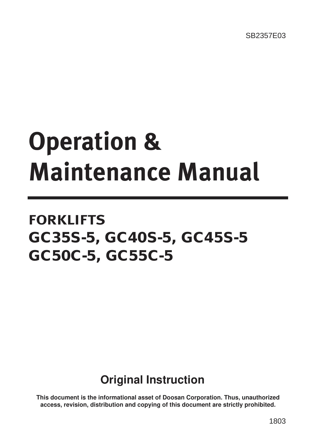
Doosan GC35S-5 GC40S-5 GC45S-5 GC50C-5 GC55C-5 Forklift Operation & Maintenance Manual

Original price was: $39.95.Current price is: $24.95.

Complete Doosan GC35S-5, GC40S-5, GC45S-5, GC50C-5 and GC55C-5 lift truck Operation & Maintenance Manual – safety, operation, lubrication, maintenance intervals, service procedures, torque specs and PSI 4.3L LP engine diagnostics in one PDF.

⚑
Instant PDF Download
Available immediately
πŸ’Ύ
Save to Your Device
Download & keep forever
πŸ›‘οΈ
Antivirus Scanned
100% virus-free
🌍
Trusted Worldwide
175,000+ customers

Description

Doosan GC35S-5 / GC40S-5 / GC45S-5 / GC50C-5 / GC55C-5 Lift Truck Operation & Maintenance Manual

This is the full Doosan Operation & Maintenance Manual for the GC40S-5 Series counterbalanced LPG lift trucks, covering the GC35S-5, GC40S-5, GC45S-5, GC50C-5 and GC55C-5 models. It is the same document that ships with the truck, reproduced here as a single PDF you can open on a laptop in the workshop, a tablet on the shop floor, or print and keep in the operator’s compartment. Everything from the daily walk-around check to engine oil and filter change intervals, mast and lift chain adjustment, tilt cylinder servicing and PSI 4.3L LP engine diagnostic trouble codes is contained in the one file.

File Details

  • Manual type: Operation & Maintenance Manual (Original Instruction)
  • Brand / manufacturer: Doosan Corporation Industrial Vehicle BG
  • Models covered: GC35S-5, GC40S-5, GC45S-5, GC50C-5, GC55C-5
  • Document numbers: SB2357E03, SB2443E02
  • Language: English
  • Page count: 2533 pages
  • File format: PDF

Chapters Covered

  • Information Section – foreword, literature information, how to use the manual
  • Safety Section – important safety information, warning signs and labels, general hazard information, parking brake, burn prevention, fire or explosion prevention, operator restraint system, avoiding lift truck tipovers, safety rules, surviving a tipover
  • General Section – Declaration of Conformity, specifications, noise and vibration, capacity charts, capacity charts with side shifter, serial number locations, operator’s warning and identification plate, mast and attachment abbreviations
  • Operation Section – operator’s station and monitoring systems, instrument panel, seat switch system, lift truck controls, refueling and changing LP tanks, before starting the engine, starting the engine, starting from a 12 volt external source, electronic controlled spark-ignition engines (PSI 4.3L LP engine), basic troubleshooting (LP), advanced diagnostics, lift truck operation, inching, steering knob, mono-ped control system, Auto Shift Controller ASC-206, operating techniques, parking the lift truck, lift fork adjustment, storage information, transportation hints, towing information
  • Maintenance Section – inspection, maintenance and repair of lift truck forks, torque specifications, cooling system specifications, fuel specifications, lubricant specifications, lubricant viscosities and refill capacities, maintenance intervals, quick reference maintenance schedule
  • When Required – fuel system leak test, seat, hood latch and support cylinder, fuses, bulbs and circuit breaker, tires and wheels, carriage roller extrusion, battery terminal
  • Every 10 Service Hours or Daily – engine fluid leaks, engine oil level, coolant level, air cleaner indicator, accelerator pedal operation, exhaust leaks, walk-around inspection, mast channels, transmission oil level, hydraulic oil level, drive axle oil level, brake oil level
  • First 50 – 100 Service Hours or a Week – transmission oil, oil filter and strainer, drive axle oil, parking brake test and adjust
  • Every 250 Service Hours or Monthly – engine oil and filter change (LP engine crankcase)
  • Every 500 Service Hours or 3 Months – air intake system check and clean, tilt cylinders, mast hinge pins, crosshead rollers, carriage side rollers thrust, carriage sideshifter, mast/carriage/lift chains and attachments, carriage side rollers, parking brake, circulation pump belt, drive axle oil and strainer (OCDB), horn and lights, vacuum lines and fittings, fuel trim valve inspection, electrical system, overhead guard, steer suspension, steering mechanism, wheel bolts and nuts
  • Every 1000 Service Hours or 6 Months – air intake system change, coolant hoses, LP regulator/converter, fuel lines and fittings, mixer assembly, throttle assembly, hydraulic return filter, air breather, transmission oil/oil filter/strainer, lift chains test/check/adjust, universal joint
  • Every 1500 Service Hours or 9 Months – drive axle oil (shoe brake only), ignition system, spark plugs, LP fuel filter element, fuel filter disassembly, fuel lock-off operation test
  • Every 2000 Service Hours or Yearly – steer wheel bearings reassembly, cooling system clean and change, fork inspection
  • Every 2500 Service Hours or 15 Months – hydraulic oil check/clean/change, battery system, TMAP sensor, intake leaks, PCV valve and breather element, oxygen sensor
  • Environment Protection Section and Index Section

Read as a whole, the document is a complete maintenance and operating reference for the GC40S-5 family rather than a collection of unrelated bulletins. The safety section sets out the warning decals fitted to the truck, the correct mounting and dismounting technique, the stability triangle and how the combined centre of gravity shifts with load, tilt and lift height, and the tipover survival procedure for trucks fitted with the operator restraint system. The general section then gives you the truck’s own specification tables, capacity charts for standard, full free lift and full free triple masts (both with and without the side shifter), and the location of the lift truck, engine, transmission and drive axle serial numbers. From there the operation section walks through every control in the operator’s station, the instrument panel warning lights and gauges, LP tank changing, the seat switch system, the inching pedal technique, the ASC-206 auto shift controller, and full lift, tilt, travel, unloading and turning technique. The maintenance section is the working heart of the manual: it groups every job by service hour interval and gives the illustrated step-by-step procedure, the torque value, the fluid specification and the adjustment tolerance for each one.

What This Manual Covers In Depth

PSI 4.3L LP Engine and G643E Engine Content

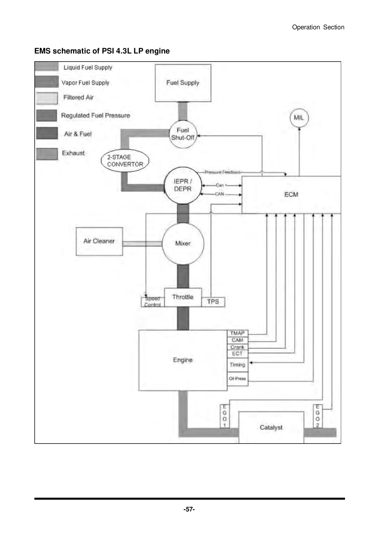
The spark-ignition engine coverage is substantial. The manual describes the closed-loop fuel system with heated exhaust gas oxygen sensors, the direct electronic pressure regulator, fuel mixer, electronic throttle control, two-stage converter, engine control module and catalytic converter. There are full diagnostics chapters: the MI-07 flash code tables and the PSI 4.3L Diagnostic Trouble Code charts, along with the procedure for entering blink code mode by jumping pins 1 and 4 at the DLC connector. Fault codes are listed by number and by SPN:FMI with the probable fault and the corrective action for each. There are also symptom-based troubleshooting tables covering no start, hard start, cuts out and misses, hesitation and sag, backfire, lack of power, rough or unstable idle, and stalling.

Maintenance and Adjustment Procedures

Alongside the interval schedule you get the actual procedures: air intake system filter element cleaning and replacement including the secondary element, tilt cylinder rod extension adjustment with the clevis thread overlap minimum, mast chain adjustment for STD, FF and FFT masts with the anchor nut procedure and Loctite application, lift chain wear measurement using the ten-link pin-centre method and the 2% wear limit, carriage roller extrusion measurement, parking brake testing on a 15% grade and the full clevis and adjustment screw procedure, steering mechanism lubrication points, wheel bolt torque sequence, and the cooling system cleaning and neutralising procedure.

Torque Values and Service Specifications

The torque section gives tables for metric hardware, standard bolts, nuts and taperlock studs, worm drive hose clamps, and metric ISO threads from M6 through M36. Individual job torque values appear inside their procedures, for example the tilt cylinder clevis pinch bolts, overhead guard mounting bolts, steer suspension mounting bolts, steer wheel bearing locknut, drive wheel nuts and spark plug torque. Lubricant viscosities are tabulated by ambient temperature for the engine crankcase, lift chains, power shift transmission, hydraulic and power steering system, drive axle housing and brake reservoir, together with refill capacities.

Complete PDF Bookmark Tree

Complete Bookmarks

The complete bookmarks in the β€œDoosan GC35S-5 GC40S-5 GC45S-5 GC50C-5 GC55C-5 Forklift Operation & Maintenance Manual” are as follows:

01. D(G)35S-5_Contents_SB4260E10p. 2
02. Safety_SB2003E01p. 3
03. Spec_SB2004E00p. 5
04. Alternator_SB4261E00p. 13
HC45 Series Alternators_SB4261E00p. 13
Indexp. 17
Specificationsp. 19
Alternatorp. 19
Systems Operationp. 20
Alternatorp. 20
Introductionp. 20
HC45 Alternator Operationp. 20
Alternator Componentsp. 21
Alternator Operation Schematicp. 23
Testing And Adjustingp. 24
Troubleshootingp. 24
Troubleshooting Problem Listp. 24
Troubleshooting Problemsp. 24
Alternatorp. 25
Alternator Output Testp. 25
Machine Testp. 25
05. S Motor_SB4262E00p. 27
Reduction Starting Motor_SB4262E00p. 27
Indexp. 31
Specificationp. 33
Starting Motorp. 33
Systems Operationp. 35
Starting Motorp. 35
Introductionp. 35
Starting Motor Componentsp. 36
Starting Motor Operation Diagramsp. 38
General Informationp. 38
Operationp. 39
Testing And Adjustingp. 41
Troubleshootingp. 41
Troubleshooting Problem Listp. 41
Troubleshooting Problemsp. 41
Starting Motorp. 42
On Machine Starting Motor DiagnosisProcedurep. 42
Off Machine No Load Testp. 45
Starting Motor Component Testsp. 46
Field Winding Continuity Testp. 47
Armature Testsp. 47
Armature Short Circuit Testp. 47
Armature Ground Testp. 48
Armature Continuity Testp. 48
Armature Runout Checkp. 48
Commutator Outside Diameter Checkp. 48
Brush and Brush Holder Checksp. 49
Brush Holder Testp. 49
Brush Length Checkp. 50
Overrunning Clutch Checkp. 50
Disassembly AndAssemblyp. 51
Starting Motorp. 51
Disassemble Starting Motorp. 51
Assemble Starting Motorp. 54
06. G643(E)_SB4263E02p. 59
G643(E)_SB4263E02.pdfp. 59
1. ImportantSafety Information.pdfp. 61
2. SB4263E02 index.pdfp. 63
3. SB4263E02 1,2μž₯.pdfp. 67
4. SB4263E02 3μž₯.pdfp. 91
5. SB4263E02 4μž₯.pdfp. 170
6. SB4263E02 5μž₯.pdfp. 200
7. SB4263E02 6μž₯.pdfp. 253
8. SB4263E02 7μž₯.pdfp. 291
9. SB4263E02 8μž₯.pdfp. 314
10. SB4263E02 appendix.pdfp. 316
07. DB58S_SB4118E01p. 322
G35/50S-5, Diesel Engine 5.8 Liter (DB58S), SB4118E01p. 322
FOREWORDp. 326
CONTENTSp. 328
1. GENERAL INFORMATIONp. 330
1.1. Engine specificationsp. 330
1. 2. Performance curvep. 331
1. 2.1. Performance curve (ECRFA), D50/60/70/80/90S-5 (3 speed)p. 331
1. 2.2. Performance curve (ECRFD), D35/40/45S-5, D50/55C-5p. 332
1. 2.3. Performance curve (ECRFE), D50/60/70S-5 (2 speed)p. 333
1.3. Engine assemblyp. 334
1.3.1. Engine assembly view (ECRFA), D50/60/70/80/90S-5 (3 speed)p. 334
1.3.2. Engine assembly view (ECRFD), D35/40/45S-5, D50/55C-5p. 335
1.3.3. Engine assembly views (ECRFE), D50/60/70S-5 (2 speed)p. 336
1.4. Safety regulationsp. 337
1.4.1. General notesp. 337
1.4.2. Regulations designed to prevent accidentsp. 337
1.4.3. Regulations designed to prevent damage to engine and premature wearp. 338
1.4.4. Regulations designed to prevent pollutionp. 339
1.4.5. Notes on safety in handling used engine oilp. 339
1.4.5. General repair instructionsp. 340
2. TECHNICAL INFORMATIONp. 341
2.1. Engine model and serial numberp. 341
2.2. Engine typep. 342
2.2.1. Cylinder blockp. 342
2.2.2. Piston con-rod / crankshaftp. 342
2.3. Engine timingp. 342
2.4. Valvesp. 343
2.5. Lubrication systemp. 343
2.5.1. Recommend of lubricating oilp. 344
2.5.2. Oil coolerp. 345
2.5.3. Oil filterp. 345
2.6. Air cleanerp. 346
2.7. Fuel systemp. 346
2.7.1. Injection pumpp. 347
2.7.2. Fuel filterp. 347
2.7.3. Fuel requirementsp. 347
2.7.4. How to select fuel oilp. 348
2.8. Cooling systemp. 349
2.8.1. Anti-freezep. 350
2.8.2. Cooling waterp. 350
2.9. V-belt tension check and adjustp. 352
2.10. Valve clearance andadjustmentp. 353
2.11. Cylinder compressionpressurep. 354
2.12. Injection nozzlep. 355
2.13. Batteryp. 355
2.14. Starting motorp. 355
2.15. Diagnosis and remedyp. 356
2.16. Engine inspectionp. 365
2.16.1. Stopping enginep. 365
2.16.2. General engine inspection cyclep. 365
2.17. Use of original parts for repair and replacementp. 366
3. Maintenancep. 367
3.1. Engine Disassemblyp. 367
3.1.1. Major part fixing nuts and boltsp. 367
3.1.2. Main structure parts (1)p. 378
3.1.3. Main structure parts (2)p. 380
3.1.4. Rocker arm disassemblyp. 382
3.1.5. Cylinder head disassemblyp. 383
3.1.6. Piston and connecting rod disassemblyp. 384
3.2. Engine Inspectionp. 386
3.2.1. Cylinder blockp. 386
3.2.2. Cylinder headp. 386
3.2.3. Valve stem and valve guideclearancep. 387
3.2.4. Valve springp. 391
3.2.5. Tappetp. 392
3.2.6. Push rodp. 392
3.2.7. Rocker arm correctionp. 393
3.2.8. Idler gear and shaftp. 394
3.2.9. Camshaftp. 394
3.2.10. Cylinder linerp. 396
3.2.11. Cylinder blockp. 397
3.2.12. Pistonp. 400
3.2.13. Maintenance of cylinder block, cylinder liner and pistonp. 403
3.2.14. Connecting rodp. 404
3.2.15. Crankshaftp. 406
3.2.16. Flywheel and flywheel housingp. 410
3.3. Engine Reassemblyp. 411
3.3.1. Piston and connecting rod assemblyp. 411
3.3.2. Cylinder head assembly partsp. 413
3.3.3. Rocker arm and shaft assemblyp. 416
3.3.4. Main componentsp. 417
3.3.5. Major component assemblyp. 423
3.3.6. External partsp. 427
4. Commissioning and Operationp. 432
4.1. Preparationp. 432
4.1.1. Startingp. 432
4.2. Starting and operationp. 433
4.2.1. Operation of a new engine (Break-In)p. 433
4.2.2. Check points for break-inp. 433
4.3. Inspections after startingp. 435
4.4. Operation in winter timep. 435
4.4.1. Prevention against the freeze of cooling waterp. 435
4.4.2. Prevention against excessive coolingp. 435
4.4.3. Lubricating oilp. 436
4.4.4. Starting of engine in winterp. 436
4.4.5. Tuning the enginep. 436
4.5. Maintenance and carep. 437
4.5.1. Periodical inspection and maintenancep. 437
4.5.2. Exchanging of lubrication oilp. 437
4.5.3. Oil levelp. 437
4.5.4. Oil exchange procedurep. 437
4.5.5. Replacement of oil filter cartridgep. 438
4.6. Cooling systemp. 439
4.6.1. Coolant drainingp. 439
4.6.2. Cleaning of the cooling inside system circuitp. 440
4.7. Valve clearance and adjustmentp. 440
4.8. Injection timingp. 442
4.9. Tightening the cylinder head boltsp. 445
4.10. Fuel injection pumpp. 445
4.11. Feed pump strainerp. 446
4.12. Separator (Add if necessary)p. 446
4.13. Air bleedingp. 446
4.14. Beltsp. 447
5. Maintenance of Major Componentsp. 450
5.1. Lubrication systemp. 450
5.1.1. Oil pumpp. 450
5.1.2. Oil coolerp. 452
5.2. Cooling systemp. 453
5.2.1. Water pumpp. 453
5.2.2. Thermostatp. 457
5.3. Fuel systemp. 458
5.3.1. Fuel filterp. 458
5.3.2. Injection nozzlep. 459
5.3.3. Injection Pump Calibrationp. 463
5.3.4. Precautions for operationp. 466
5.3.5. Walk-around check and servicingp. 467
5.3.6. Diagnostics and troubleshootingp. 468
6. Special Tool Listp. 469
β€’ Appendixp. 471
08. D439E_SB4323E01p. 474
G35/50S-5, D439E Diesel Engine, SB4323E00p. 474
Indexp. 478
1. General Informationp. 482
Generalp. 482
Generalp. 482
General Precautions for Servicingp. 486
2. Engine MechanicalSystem (D439E)p. 491
Generalp. 491
Descriptionp. 491
Specificationp. 495
Tightening Torquep. 499
Special Toolp. 503
Diagnosisp. 505
Adjustmentp. 507
Timing Systemp. 508
Timing Gear Assemblyp. 508
Removalp. 510
Inspectionp. 514
Replacementp. 517
Installationp. 518
Cylinder head Assemblyp. 524
Componentsp. 524
Removalp. 526
Disassemblyp. 529
Inspectionp. 530
Replacementp. 534
Reassemblyp. 536
Installationp. 538
Crankcasep. 540
Flywheelp. 540
Removalp. 541
Inspectionp. 541
Installationp. 542
Cylinder Block Assemblyp. 544
Componentsp. 544
Removalp. 546
Disassemblyp. 549
Inspectionp. 550
Reassemblyp. 556
Installationp. 557
Intake and Exhaust Systemp. 561
Specificationsp. 561
Troubleshootingp. 562
Turbochargerp. 564
Componentsp. 564
Removalp. 566
Inspectionp. 567
Installationp. 568
Intake Manifoldp. 570
Componentsp. 570
Removalp. 571
Installationp. 572
Exhaust Manifoldp. 573
Componentsp. 573
Removalp. 574
Installationp. 575
Lubrication Systemp. 576
Descriptionp. 576
Specificationp. 580
Troubleshootingp. 582
Adjustmentp. 584
Oil Pumpp. 586
Componentsp. 586
Disassemblyp. 588
Inspectionp. 590
Oil Coolerp. 589
Componentsp. 589
Disassemblyp. 590
Cooling Systemp. 592
Descriptionp. 592
Specificationp. 593
Trouble Shootingp. 595
Water pumpp. 597
Componentsp. 597
Removalp. 598
Inspectionp. 599
Installationp. 600
3. Engine Electrical System (D439E)p. 601
Generalp. 601
Specificationp. 601
Service Standardsp. 603
Troubleshootingp. 604
Charging Systemp. 606
Descriptionp. 606
Adjustmentp. 607
Alternatorp. 611
Componentsp. 611
Disassemblyp. 612
Inspectionp. 614
Reassemblyp. 615
Starting Systemp. 616
Descriptionp. 616
Inspectionp. 617
Preheating Systemp. 619
Preheating Plugp. 619
4. Fuel Systemp. 620
Generalp. 620
Specificationp. 620
Sealantp. 621
Tightening Torquep. 621
Troubleshootingp. 621
Engine controlp. 623
Engine Starting Systemp. 623
Fuel Tank and Fuel Linep. 624
Troubleshooting Procedurep. 625
Troubleshooting Procedurep. 629
Engine Control System-Electronicp. 642
Descriptionp. 642
Engine Control Unit (ECU)p. 645
ECU Pin Connectorp. 645
ECU Circuit Diagramp. 650
Removalp. 652
Inspectionp. 653
Intake Air Temperature Sensorp. 659
Inspectionp. 659
Intake Air Pressure Sensorp. 660
Inspectionp. 660
Coolant Temperature Sensorp. 661
Inspectionp. 661
Installationp. 662
Camshaft Position Sensorp. 663
Inspectionp. 663
Crankshaft Position Sensorp. 664
Inspectionp. 664
Rail Pressure Sensorp. 665
Inspectionp. 665
Supply Control Valvep. 666
Inspectionp. 666
Fuel Delivery System-Electronicp. 667
Componentsp. 667
Fuel Filterp. 668
Replacementp. 668
Inspectionp. 668
Assemblyp. 668
Injectorp. 669
Componentsp. 669
Cleaningp. 670
Removalp. 670
Replacementp. 671
Injector Replacementp. 672
ECU Replacementp. 672
Installationp. 673
Common Rail Assemblyp. 674
Removalp. 674
Installationp. 674
Injection Pump-Electronicp. 675
Supply pumpp. 675
5. Service Toolp. 678
Check before usep. 678
Read me firstp. 678
Safety Warning and Caution before Usep. 679
Hardwarep. 683
Specificationp. 683
Introduction of Componentsp. 686
Basic Usage of G-scanp. 687
Power supplyp. 687
Power ON/OFFp. 690
Description for Main Components of H/Wp. 692
Description for layout of S/W screenp. 697
Connecting the DLC cablep. 701
Self Test Adapterp. 704
Configurationp. 705
Setupp. 705
User Informationp. 713
Versionp. 716
Self Testp. 718
STEP-B Testp. 722
Vehicle Communication Functionp. 725
Vehicle Selectionp. 725
Fault Code Searchingp. 732
DTC Analysisp. 735
Actuation Testp. 755
Vehicle S/W Managementp. 757
ECU Upgradep. 761
CARB OBD-IIp. 774
Flight Recordp. 780
PC Utilityp. 800
PC Utility Installationp. 800
How to use PC Utilityp. 809
Appendixp. 827
Optional Item Installation and Expenditure Exchangep. 827
O/S Updatep. 831
6. DTC Troubleshooting proceduresp. 838
09. V3800 T4_SB4401E01p. 885
Service ManualV3800 Diesel Engine (Tier-β…£ Interim) SB4401E01p. 885
Indexp. 889
Specificationsp. 893
Preformance Curvesp. 894
Wiring Diagramp. 896
Engine Intermediate Harness (Engine Side Harness)p. 896
Injector Intermediate Harness (Engine Side Harness)p. 898
ECU Intermediate Harness (One Side Harness)p. 899
System Wiring Diagramp. 904
Generalp. 905
Engine Identificationp. 905
Model Name and Engine Serial Numberp. 905
E4B Enginep. 906
Cylinder Numberp. 906
Muffler Full Assembly Identificationp. 907
Part Number and Serial Numberp. 907
General Precautionsp. 908
Maintenance Check Listp. 909
Check and Maintenancep. 913
Daily Check Pointsp. 913
Initial 50 Hoursp. 916
Every 50 Hoursp. 917
Every 250 Hoursp. 917
Every 500 Hoursp. 919
Every 1000 Hoursp. 922
Every 1500 Hoursp. 923
Every 3000 Hoursp. 925
Every 1 Yearp. 930
Every 2 Yearsp. 931
Special Toolsp. 935
Enginep. 943
Enginep. 943
Cylinder Blockp. 943
Cylinder Headp. 943
Pistonp. 944
Lubricating Systemp. 945
Oil Coolerp. 945
Cooling Systemp. 946
Thermostatp. 946
Bottom Bypass Systemp. 947
Common Rail System (CRS)p. 948
Overviewp. 948
Supply Pumpp. 949
Railp. 952
Injectorp. 953
Engine Control Systemp. 956
EGR Systemp. 960
Overviewp. 960
EGR Valvep. 960
Reed Valvep. 961
After Treatment Systemp. 962
After Treatment Devicesp. 962
Troubleshootingp. 967
Servicing Specificationsp. 971
Tightening Torquesp. 977
Tightening Torques Of Screws, Bolts And Nuts for General Usep. 977
Tightening Torques Of Screws, Bolts And Nuts For Special Usep. 978
Checking, Disassembling and Servicingp. 980
Checking and Adjustingp. 980
Disassembling and Assemblingp. 988
Engine Body and Servicingp. 1025
DPF (Diesel Particulate Filter)p. 1045
Function of Diesel Particulate Filter (DPF)p. 1045
DPF Regeneration and DPF Cleaningp. 1046
DPF Cleaning Flowp. 1047
DPF Cleaning Procedurep. 1048
To Ensure Safety And Good Performance In DPF Cleaning Procedurep. 1048
Separation Of DPF Muffler Full Assyp. 1048
Disassembly Of DPF MufflerFull Assyp. 1050
Judgement Of Reuse Of DPF Filter Comp Before Cleaningp. 1051
Preparation Of "After-Treatment Device Exchange Report Form"p. 1052
Preparation Of "DPF Cleaning Order Form"p. 1052
Packing, Delivering, And Handling Standard Of DPF Filter Compp. 1053
Judgement Of Reuse Of DPF Filter CompAfter Cleaningp. 1054
Assembly of DPF Muffler Full Assyp. 1055
Mounting of DPF Muffler Full Assyp. 1057
Resetting By Using Diagnosis Tool(When Installing Cleaned DPF)p. 1058
Resetting By Using Diagnosis Tool(When Installing New DPF)p. 1063
Execution Condition For Manual Regenerationp. 1065
Attached Formp. 1066
Common Rail Systemp. 1069
Basic System Informationp. 1069
System Configurationp. 1069
Fuel Systemp. 1069
Intake and Exhaust Systemp. 1070
Wiring Diagramp. 1070
Engine Intermediate Harness (Engine Side Harness)p. 1070
Injector Intermediate Harness (Engine Side Harness)p. 1071
ECU Intermediate Harness (One Side Harness)p. 1072
System Wiring Diagramp. 1074
Available Data Monitor Signals (Level 1)p. 1075
Monitor Itemsp. 1075
Normal Valuep. 1076
ECU Terminal Layoutp. 1078
ECU Terminal Layout 1 (Engine Side)p. 1078
ECU Terminal Layout 2 (Machine Side)p. 1079
General Servicep. 1081
Overall Diagnostic Procedurep. 1081
Questioningp. 1081
List of Malfunction Symptomp. 1083
Actions for Non-Reoccurring Malfunctionsp. 1083
Diagnostic Tool Connection Procedurep. 1084
Diagnostic Connector Positionsp. 1084
Diagnostic Tool Connection Procedurep. 1084
Checking the Communication Operation of the Interface (DST-i)p. 1085
Checking the Operation of the ECUp. 1085
Starting Diagmasterp. 1085
DST-i Communication Settingsp. 1086
Active Test and Supply Pump Difference Learningp. 1088
Diagnosis by Malfunction Symptomp. 1089
List of Malfunction Causes by Symptomp. 1089
Diagnosis by Malfunction Symptomp. 1091
Engine Warning Light Comes Onp. 1091
Engine Does Not Startp. 1091
Takes A Long Time Before Engine Startsp. 1093
Idle Failurep. 1096
Engine Noisep. 1098
High fuel consumptionp. 1099
Poor Acceleration (Insufficient Output)p. 1102
Abnormal Black Smoke Emittedp. 1104
Abnormal White Smoke Emittedp. 1107
Engine Stalls on Decelerationp. 1109
Diagnostic Procedure by DTCp. 1111
DTC Listp. 1111
Diagnostic Procedure by DTCp. 1147
NE – G Phase Shift (DTC P0016 / 636-7)p. 1148
Intake Air Temperature Built-in MAF Sensor: Abnormality (DTC P0072 / 171-4, DTCP0073 / 171-3)p. 1149
Pressure Limiter Emergency Open (DTC P0087 / 633-7)p. 1150
High Rail Pressure (DTC P0088 / 157-0)p. 1153
SCV Stuck (DTC P0089 / 1347-7)p. 1155
Fuel Leak (in High Pressured Fuel System) (DTC P0093 / 1239-1)p. 1158
MAF Sensor Power Supply: High (24 V-System Only) (DTC P0100 / 132-16)p. 1161
Intake Air Volume: Low (DTC P0101 / 132-1)p. 1162
MAF Sensor Abnormality (DTC P0102 / 132-4, P0103 / 132-3)p. 1162
MAF Sensor Power Supply: Low (24 V-System Only) (DTC P0104 / 132-18)p. 1163
Intake Air Temperature: High (Inter Cooler Model Only) (DTC P0111 / 172-0)p. 1164
Intake Air Temperature Error (DTC P0112 / 172-4, P0113 / 172-3)p. 1165
Coolant Temperature Sensor Abnormality (DTC P0117 / 110-4, P0118 / 110-3)p. 1166
Fuel High Temperature (DTC P0181 / 174-0)p. 1168
Fuel Temperature Sensor Abnormality (DTC P0182 / 174-4, P0183 / 174-3)p. 1168
Rail Pressure Sensor Abnormality (DTC P0192 / 157-4, P0193 / 157-3)p. 1170
Injector Charge Voltage: High (DTC P0200 / 523535-0)p. 1172
Open Circuit of Harness/Coil (DTC P0201 / 651-3, P0202 / 653-3, P0203 / 654-3, P0204 /652-3)p. 1173
Engine Overheat (DTC P0217 / 110-0)p. 1174
Engine Overrun (DTC P0219 / 190-0)p. 1175
Boost Pressure Sensor Abnormality (DTC P0237 / 102-4, P0238 / 102-3)p. 1176
Crankshaft Position Sensor (NE Sensor) Abnormality (DTC P0335 / 636-8, P0336 /636-2)p. 1178
Camshaft Position Sensor (G Sensor) Abnormality (DTC P0340 / 723-8, P0341 / 723-2)p. 1180
Air Heater Relay Driving Circuit Abnormality (DTC P0380 / 523544-3 / 523544-4)p. 1183
EGR Actuator Abnormality (DTC P0403 / 523574-3, DTC P0404 / 523574-4, P0409 /523572-4)p. 1185
Oil Pressure Error (P0524 / 100-1)p. 1186
Exhaust Gas Temperature Sensor 1 (T1) Abnormality (DTC P0543 / 3242-4, P0544 /3242-3)p. 1187
Exhaust Gas Temperature Sensor 0 (T0) Abnormality (DTC P0546 / 4765-4, P0547 /4765-3)p. 1189
Battery Voltage Abnormality (DTC P0562 / 168-4, P0563 / 168-3)p. 1190
QR Data Abnormality (DTC P0602/523538-2, P0602/523538-7)p. 1192
ECU Flash-ROM and CPU Abnormality (DTC P0605 / 628-2, P0606 / 1077-2, P0606/523527-2)p. 1193
Injector Charge Voltage Abnormality (DTC P0611 / 523525-1)p. 1194
SCV Drive System Abnormality (DTC P0628 / 1347-4, P0629 / 1347-3)p. 1195
Sensor Supply Voltage 1 Abnormality (DTC P0642 / 3509-4, P0643 / 3509-3)p. 1197
Sensor Supply Voltage 2 Abnormality (DTC P0652 / 3510-4, P0653 / 3510-3)p. 1198
Sensor Supply Voltage 3 Abnormality (DTC P0662 / 3511-4, P0663 / 3511-3)p. 1199
Sensor Supply Voltage 4 Abnormality (DTC P0672 / 3512-4, P0673 / 3512-3)p. 1200
Main Relay is Locked in Closed Position (DTC P0687 / 1485-2)p. 1201
Pump Seizing (DTC P1274 / 523539-2, P1275 / 523540-2)p. 1202
EEPROM Check Sum Error (DTC P1990 / 523700-13)p. 1205
Intake Throttle Feedback Error (DTC P2108 / 523580-2)p. 1205
Accelerator Position Sensor 1 Abnormality (DTC P2122 / 91-4, P2123 / 91-3)p. 1206
Accelerator Position Sensor 2 Abnormality (DTC P2127 / 29-4, P2128 / 29-3)p. 1208
Accelerator Position Sensor Error (CAN) (DTC P2131 / 523543-2)p. 1210
Accelerator Position Sensor Correlation Error (DTC P2135 / 91-2)p. 1211
Common 1 System Injector Drive Circuit Open (DTC P2146 / 523523-2)p. 1212
Common 1 TWV Actuation System Short (DTC P2147 / 523523-4, P2148 / 523523-3)p. 1213
Common 2 TWV Actuation System Short (DTC P2150 / 523524-4, P2151 / 523524-3)p. 1217
Barometric Pressure Sensor Error (DTC P2228 / 108-4, P2229 / 108-3)p. 1219
EGR (DC Motor) Abnormality (DTC P2413 / 523575-7, P2414 / 523576-2, P2415 /523577-2)p. 1220
Exhaust Gas Temperature Sensor 2 (T2) Abnormality (DTC P242C / 3246-4, P242D /3246-3)p. 1222
Differential Pressure Sensor 1 Abnormality (DTC P2454 / 3251-4, P2455 / 3251-3)p. 1223
Intake Throttle Lift Sensor Abnormality (DTC P2621 / 523583-4, P2622 / 523582-3)p. 1225
Emission Deterioration (DTC P3001 / 3252-0)p. 1226
Exhaust Gas Temperature Sensor 0: Emergency High (DTC P3002 / 4765-0)p. 1227
Exhaust Gas Temperature Sensor 1: Emergency High (DTC P3003 / 3242-0)p. 1228
Exhaust Gas Temperature Sensor 2: Emergency High (DTC P3004 / 3246-0)p. 1229
Excessive PM3 (DTC P3006 / 3701-15)p. 1231
Excessive PM4 (DTC P3007 / 3701-16)p. 1231
Excessive PM5 (DTC P3008 / 3701-0)p. 1232
Boost Pressure Low (DTC P3011 / 132-15)p. 1232
Low Coolant Temperature in Parked Regeneration (DTC P3012 / 523589-17)p. 1233
Parked Regeneration Time Out (DTC P3013 / 523590-16)p. 1234
All Exhaust Gas Temperature Sensor Failure (DTC P3018 / 523599-0)p. 1235
Initial Pump-calibration Incomplete (DTC P3019 / 523600-0)p. 1235
High Exhaust Gas Temperature After Emergency High Temperature DTC (DTC P3023/ 523601-0)p. 1236
High Frequency of Regeneration (DTC P3024 / 523602-0)p. 1236
Over Heat Pre-caution (DTC P3025 / 523603-15)p. 1237
CAN2 Bus Off (DTC U0075 / 523547-2)p. 1238
No Communication with EGR (DTC U0076 / 523578-2)p. 1239
CAN1 Bus Off (DTC U0077 / 523604-2)p. 1240
CAN2 Frame Error (DTC U0081 / 523548-2, U0082 / 523591-2, U0083 / 523592-2, U0084/ 523593-2, U0085 / 523594-2, U0086 / 523595-2, U0087 / 523596-2, U0089 / 523598-2)p. 1240
Inspection Procedure for Each Systemp. 1242
Air Intake System Inspection Procedurep. 1242
Fuel System Inspection Procedurep. 1243
Electric System Inspection Procedurep. 1245
Basics of Checking Electrical / Electronic Circuit Systemsp. 1245
Connector Connection Fault Verification Methodp. 1247
Checking the Power and Ground System (Main Relay, ECU Circuit)p. 1247
10. PSI 4.3 Engine service manual_SB4460E00p. 1250
PSI 4.3L LP Engine Service Manual(SB4460E00)p. 1250
CONTENTSp. 1250
Important Safety Informationp. 1252
Indexp. 1254
Chapter 1. General Informationp. 1260
The Specification of PSI 4.3L SI Enginep. 1260
PSI 4.3L LP Engine Performancep. 1262
PSI 4.3L Certified LP Engine Emission – EPA Certification Levelsp. 1262
PSI 4.3L LP Engine Power & Torque Curvep. 1263
PSI 4.3L LP Engine BSFC Curve:p. 1263
Engine Mechanical – 4.3Lp. 1264
Fastener Tightening Specificationsp. 1264
Engine Mechanical Specificationsp. 1265
Tier 3 Certified Mobile Engine Maintenance Requirementsp. 1268
Chapter 2. Engine Mechanicalp. 1269
Diagnostic Information and Proceduresp. 1269
Base Engine Misfire Diagnosisp. 1269
Engine Compression Testp. 1271
Engine Noise Diagnosisp. 1272
Valve Train Diagnosisp. 1274
Oil Consumptionp. 1277
Oil Pressure Diagnosis and Testingp. 1277
Symptoms – Drive Beltp. 1280
Drive Belt Chirping Diagnosisp. 1281
Drive Belt Squeal Diagnosisp. 1283
Drive Belt Whine Diagnosisp. 1285
Drive Belt Rumbling Diagnosisp. 1286
Drive Belt Vibration Diagnosisp. 1288
Drive Belt Falls Off Diagnosisp. 1290
Drive Belt Excessive Wear Diagnosisp. 1292
Drive Belt Tensioner Diagnosisp. 1293
Engine Identificationp. 1294
Special Tools and Equipmentp. 1295
Draining Fluids and Oil Filter Removalp. 1298
Engine Flywheel Removalp. 1299
Clutch Pilot Bearing Removalp. 1300
Exhaust Manifold Removal (Left)p. 1301
Exhaust Manifold Removal (Right)p. 1302
Oil Level Indicator and Tube Removalp. 1303
Water Pump Removalp. 1304
Crankshaft Balancer Removalp. 1305
Valve Rocker Arm Cover Removal (Left)p. 1307
Valve Rocker Arm Cover Removal(Right)p. 1308
Distributor Removalp. 1309
Intake Manifold Removalp. 1310
Valve Rocker Arm and Push RodRemovalp. 1311
Cylinder Head Removal (Left)p. 1312
Cylinder Head Removal (Right)p. 1315
Valve Lifter Removalp. 1317
Oil Pan Removalp. 1318
Oil Pump Removalp. 1319
Engine Front Cover Removalp. 1320
Timing Chain and Sprockets Removalp. 1321
Balance Shaft Removalp. 1324
Camshaft Removalp. 1326
Piston, Connecting Rod, and BearingRemovalp. 1327
Crankshaft Rear Oil Seal and HousingRemovalp. 1329
Crankshaft and Bearings Removalp. 1331
Engine Block Plug Removalp. 1333
Engine Block Clean and Inspectp. 1337
Cylinder Boring and Honingp. 1339
Boring Procedurep. 1341
Piston and Connecting RodDisassemblep. 1342
Piston, Connecting Rod and BearingsClean/ Inspectp. 1343
Piston Selectionp. 1347
Piston and Connecting Rod Assemblep. 1348
Crankshaft and Bearings Clean andInspectp. 1350
Measuring Crankshaft BearingClearancesp. 1354
Micrometer Method for CrankshaftBearingsp. 1355
Measuring Connecting Rod BearingClearances (J 43690 Method)p. 1356
Measuring Crankshaft BearingClearances (Plastic Gauge Method)p. 1363
Measuring Connecting Rod Bearing SideClearancep. 1365
Crankshaft Balancer Clean and Inspectp. 1365
Engine Flywheel Clean and Inspectp. 1366
Camshaft and Bearings Clean andInspectp. 1368
Camshaft Bearing Removalp. 1370
Camshaft Bearing Installationp. 1372
Balance Shaft Bearing and/or BushingRemovalp. 1375
Balance Shaft Clean and Inspectp. 1376
Balance Shaft Bearing and/or BushingInstallationp. 1377
Timing Chain and Sprockets Clean andInspectp. 1378
Valve Rocker Arm and Push Rods Cleanand Inspectp. 1379
Valve Lifters and Guides Clean andInspectp. 1380
Cylinder Head Disassemblep. 1381
Cylinder Head Clean and Inspectp. 1382
Valve Guide Reaming/Valve and SeatGrindingp. 1385
Cylinder Head Assemblep. 1387
Oil Pump Disassemblep. 1389
Oil Pump Clean and Inspectp. 1391
Oil Pump Assemblep. 1392
Valve Rocker Arm Cover Clean andInspectp. 1394
Oil Pan Clean and Inspectp. 1395
Exhaust Manifold Clean and Inspectp. 1396
Water Pump Clean and Inspectp. 1397
Thread Repairp. 1398
Service Prior to Assemblyp. 1399
Engine Block Plug Installationp. 1400
Crankshaft and Bearings Installationp. 1405
Specificationp. 1407
Crankshaft Rear Oil Seal and HousingInstallationp. 1408
Piston, Connecting Rod and BearingInstallationp. 1410
Camshaft Installationp. 1414
Balance Shaft Installationp. 1415
Timing Chain and Sprockets Installationp. 1419
Engine Front Cover Installationp. 1421
Oil Pump Installationp. 1422
Oil Pan Installationp. 1423
Crankshaft Balancer Installationp. 1425
Valve Lifter Installationp. 1428
Cylinder Head Installation (Left)p. 1429
Cylinder Head Installation (Right)p. 1432
Valve Rocker Arm and Push RodInstallationp. 1435
Intake Manifold Installationp. 1437
Distributor Installationp. 1439
Valve Rocker Arm Cover Installation(Left)p. 1442
Valve Rocker Arm Cover Installation(Right)p. 1443
Oil Level Indicator and Tube Installationp. 1444
Water Pump Installationp. 1445
Exhaust Manifold Installation (Left)p. 1446
Exhaust Manifold Installation (Right)p. 1447
Clutch Pilot Bearing Installationp. 1447
Engine Flywheel Installationp. 1448
Engine Set-Up and Testingp. 1449
Description and Operationp. 1450
Engine Component Descriptionp. 1450
Drive Belt System Descriptionp. 1450
New Product Informationp. 1451
Lubricationp. 1452
Cleanliness and Carep. 1453
Replacing Engine Gasketsp. 1453
Use of RTV and Anaerobic Sealerp. 1453
Separating Partsp. 1456
Tools and Equipmentp. 1456
General Informationp. 1457
Introductionp. 1457
Servicing Your Emissions CertifiedEnginep. 1457
Fuel Qualityp. 1457
Fuel System Cautionsp. 1457
Warnings, Cautions and Notesp. 1457
Proper Use of This Service Manual,Tools and Equipmentp. 1457
Maintenancep. 1459
Serpentine Belt Systemp. 1459
Cooling Systemp. 1459
Coolantp. 1459
Engine Electrical System Maintenancep. 1460
Engine Crankcase Oilp. 1460
Oil Recommendationp. 1460
Synthetic Oilsp. 1460
Checking/Filling Engine Oil Levelp. 1461
Changing the Engine Oilp. 1461
Fuel System Inspection andMaintenancep. 1462
Gasoline and LPG Fuel Systemp. 1462
Inspection and Maintenance of the FuelStorage Cylinderp. 1462
Inspection and Replacement of the FuelFilterp. 1462
Replacing the Fuel Filter:p. 1462
Direct Electronic Pressure Regulator(DEPR) Maintenance and Inspectionp. 1463
Checking/Draining Oil Build-Up in theVaporizer Regulatorp. 1463
Air Fuel Mixer/Throttle Control DeviceMaintenance and Inspectionp. 1464
Exhaust System and Catalytic ConverterInspection and Maintenancep. 1464
Chapter 3. Fuel Systemp. 1465
LPG Fuel Systemp. 1465
Description and Operation of the FuelSystemsp. 1466
LP Fuel Systemp. 1466
Service Linesp. 1466
Fuel Filterp. 1466
Electric Fuel Lock-Off Valvep. 1466
Direct Electronic Pressure Regulator(DEPR)p. 1466
Air Fuel Mixerp. 1467
Light Duty 2-Stage Vaporizerp. 1468
Electronic Throttle Control Device (ETC)p. 1468
Three-Way Catalytic Converterp. 1468
Engine Control Modulep. 1469
Heated Exhaust Gas Oxygen Sensorsp. 1469
TMAP Sensorp. 1470
Coolant Temperature Sensorp. 1470
Oil Pressure Senderp. 1470
LD 2-Stage Regulator Nominal PressureSpecificationsp. 1470
Fuel System Diagnosisp. 1471
Fuel System Descriptionp. 1471
Diagnostic Aidsp. 1471
Test Descriptionp. 1471
How the Correction Factors Workp. 1472
Determining Total Fuel Correctionp. 1472
Normal & Abnormal Fuel Correctionp. 1472
Fuel System Symptom Diagnosticsp. 1473
Intermittentp. 1474
No Startp. 1475
No Startp. 1476
Hard Startp. 1477
Hard Startp. 1478
Cuts Out, Missesp. 1479
Hesitation, Sag, Stumblep. 1480
Backfirep. 1481
Lack of Power, Sluggishness, or Sponginessp. 1482
Rough, Unstable, or Incorrect Idle, Stallingp. 1483
Electrical Sectionp. 1485
PSI 4.3L LPGp. 1485
Diagnostic Scan Tool (DST)p. 1486
Contentsp. 1486
DST Installation Instructionsp. 1486
Password Loginp. 1488
Password Dialog Box Functionsp. 1488
Connecting the PC to the Engine WireHarnessp. 1489
DST Service Pagesp. 1490
DBW Test Modep. 1491
External Power Testp. 1491
Plot/Log Menu Functionsp. 1492
DST Plot Interface Functionsp. 1494
Snapshot Hot Key Functionsp. 1494
DST Loggerp. 1495
Malfunction Indicator Lamp (MIL)p. 1495
Diagnostic Trouble Codes (DTC)p. 1495
DLC Communication Errorp. 1496
Blink Code Functionp. 1496
Intermittent Problemsp. 1497
Engine Wire Harness Repairp. 1498
ON-Vehicle Service Wire Harness Repairp. 1498
Connectors and Terminalsp. 1498
Micro-Packp. 1499
Metri-Packp. 1499
Weather-Packp. 1499
Weather-Pack Terminal Repairp. 1500
Diagnostic Trouble Codes (DTCs)p. 1501
Malfunction Indicator Lamp (MIL) Operationp. 1501
Diagnostic Trouble Code (DTC) Chart – Sorted By DTC # (1 Of 4)p. 1502
Diagnostic Trouble Code (DTC) Chart – Sorted By DTC # (2 Of 4)p. 1503
Diagnostic Trouble Code (DTC) Chart – Sorted By DTC # (3 Of 4)p. 1504
Diagnostic Trouble Code (DTC) Chart – Sorted By DTC # (4 Of 4)p. 1505
Diagnostic Trouble Code (DTC) Chart – Sorted By SPN:FMI (1 Of 4)p. 1506
Diagnostic Trouble Code (DTC) Chart – Sorted By SPN:FMI (2 Of 4)p. 1507
Diagnostic Trouble Code (DTC) Chart – Sorted By SPN:FMI (3 Of 4)p. 1508
Diagnostic Trouble Code (DTC) Chart – Sorted By SPN:FMI (4 Of 4)p. 1509
OBD System Check/MIL (Malfunction Indicator Lamp)p. 1510
OBD System Checkp. 1511
Starter Circuit System Diagnosticsp. 1512
HVS Ignition Control System Diagnosticsp. 1513
Ignition Control System Diagnostic Chartp. 1514
DTC 11 – Intake Cam / Distributor Position Error (SPN 520800:FMI 7)p. 1516
DTC 107-MAP Low Voltage (SPN 106:FMI 4)p. 1517
DTC 108-MAP High Pressure (SPN 106:FMI 16)p. 1521
DTC 111-IAT Higher Than Expected 1 (SPN 105:FMI 15)p. 1524
DTC 112-Iat Low Voltage (SPN 105:FMI 4)p. 1526
DTC 113-Iat High Voltage (SPN 105:FMI 3)p. 1529
DTC 116-Ect Higher Than Expected 1 (SPN 110:FMI 15)p. 1532
DTC 117-Ect/Cht Low Voltage (SPN 110:FMI 4)p. 1534
DTC 118-Ect/Cht High Voltage (SPN 110:FMI 3)p. 1537
DTC 121-TPS 1 Lower Than TPS 2 (TPS 51:FMI 1)p. 1540
DTC 122-TPS 1 Low Voltage (TPS 51:FMI 4)p. 1543
DTC 123-TPS 1 High Voltage (TPS 51:FMI 3)p. 1546
DTC 127-IAT Higher Than Expected 2 (TPS 105:FMI 0)p. 1549
DTC 129-BP Low Pressure (TPS 108: FMI 1)p. 1551
DTC 134-EGO 1 Pre Cat Open/Lazy (TPS 724:FMI 10)p. 1555
DTC 154-EGO 2 Pre Cat Open/Lazy (TPS 520208:FMI 10)p. 1558
DTC 217-ECT Higher Than Expected 2 (TPS 110:FMI 0)p. 1561
DTC 219-Max Govern Speed Override (TPS 515:FMI 15)p. 1563
DTC 221-TPS 1 Higher Than TPS 2 (TPS 51:FMI 0)p. 1565
DTC 222-TPS 2 Signal Voltage Low (TPS 520251:FMI 4)p. 1568
DTC 223-TPS 2 Signal Voltage High (TPS 520251:FMI 3)p. 1571
DTC 336-Crank Sync Noise (TPS 636:FMI 2)p. 1574
DTC 337-Crank Loss (TPS 636:FMI 4)p. 1577
DTC 341-Camshaft Sync Noise (TPS 723:FMI 2)p. 1580
DTC 342-Camshaft Sensor Loss (TPS 723:FMI 4)p. 1583
DTC-359 Fuel Run-Out Longer Than Expected (SPN 1239:FMI 7)p. 1586
DTC 502 – Loss of Road Speed (SPN 84:FMI 1)p. 1588
DTC 520-Oil Pressure Low Stage 1 (TPS 100:FMI 18)p. 1590
DTC 521- Oil Pressure High (SPN 100:FMI 0)p. 1592
DTC 522- Oil Pressure Sender Low Voltage (SPN 100:FMI 4)p. 1594
DTC 523- Oil Pressure Sender High Voltage (SPN 100:FMI 3)p. 1596
DTC 524-Oil Pressure Low Stage 2 (TPS 100:FMI 1)p. 1598
DTC 562-System Voltage Low (TPS 168:FMI 17)p. 1601
DTC 563-System Voltage High (TPS 168:FMI 15)p. 1603
DTC 601-Flash Checksum Invalid (TPS 628:FMI 13)p. 1605
DTC 604-Ram Failure (TPS 630:FMI 12)p. 1607
DTC 606-Cop Failure (TPS 629:FMI 31)p. 1609
DTC 642-External 5 Volt 1 Reference Low (TPS 1079:FMI 4)p. 1611
DTC 643-External 5 Volt 1 Reference High (TPS 1079:FMI 3)p. 1614
DTC 650-MIL Control Open (TPS:1213:FMI 5)p. 1616
DTC 652-External 5 Volt 2 Reference Low (SPN 1080:FMI 4)p. 1619
DTC 653-External 5 Volt 2 Reference High (SPN 1080:FMI 3)p. 1621
DTC 685-Relay Coil Open (SPN 1485:FMI 5)p. 1623
DTC 686-Relay Control Ground Short (SPN 1485:FMI 4)p. 1626
DTC 687-Relay Coil Short to Power (SPN 1485:FMI 3)p. 1628
DTC 1111-Fuel Rev Limit (SPN 515:FMI 16)p. 1631
DTC 1112-Spark Rev Limit (SPN 515: FMI 0)p. 1633
DTC 1121 FPP 1 and 2 Redundancy Lost (SPN 91: FMI 31)p. 1635
DTC 1151-Closed Loop Multiplier High LPG (SPN 520206:FMI 0)p. 1637
DTC 1152-Closed Loop Multiplier Low LPG (SPN 520206:FMI 1)p. 1640
DTC 1161-Adaptive Learn High LPG (SPN 520202:FMI 0)p. 1642
DTC 1162-Adaptive Learn Low (LPG) (SPN 520202:FMI 1)p. 1645
DTC 1165-LPG Catalyst Monitor (SPN 520213:FMI 10)p. 1647
DTC 1171-EPR Pressure Higher Than Expected (SPN 520260:FMI 0)p. 1648
DTC 1172-EPR Pressure Lower Than Expected (SPN 520260:FMI 1)p. 1650
DTC 1173-EPR Communication Lost (SPN 520260:FMI 31)p. 1652
DTC 1174-EPR Supply Voltage High (SPN 520260:FMI 3)p. 1655
DTC 1175-EPR Supply Voltage Low (SPN 520260:FMI 4)p. 1657
DTC 1176-EPR Internal Actuator Fault (SPN 520260:FMI 12)p. 1660
DTC 1177-EPR internal Circuitry Fault (SPN 520260:FMI 12)p. 1662
DTC 1178-EPR Internal Communication Error (SPN 520260:FMI 12)p. 1664
DTC 1511 – Auxiliary Analog PU 1 High Voltage (SPN 520216:FMI 3)p. 1666
DTC 1552: AUX digital 1 low voltage (SPN 520222: FMI 04)p. 1668
DTC 1612-RTI 1 Loss (SPN 629:FMI 31)p. 1670
DTC 1613-RTI 2 Loss (SPN 629:FMI 31)p. 1672
DTC 1614-RTI 3 Loss (SPN 629:FMI 31)p. 1674
DTC 1615-A/D Loss (SPN 629:FMI 31)p. 1676
DTC 1616-Invalid Interrupt (SPN 629:FMI 31)p. 1678
DTC 1625 – J1939 Shutdown Request (SPN 1384:FMI 31)p. 1680
DTC 1626-CAN Tx Failurep. 1681
DTC 1627-CAN Rx Failure (SPN 639:FMI 12)p. 1684
DTC 1628-CAN Address Conflict (SPN 639:FMI 13)p. 1686
DTC 1644-MIL Control Ground Short (SPN 1213:FMI 4)p. 1688
DTC 1645-MIL Control Ground Short To Power (SPN 1213:FMI 3)p. 1691
DTC 2111-Unable To Reach Lower TPS (SPN 51:FMI 7)p. 1694
DTC 2112-Unable To Reach Higher TPS (SPN 51:FMI 7)p. 1697
DTC 2121-FPP 1 Lower Than FPP 2 (SPN 91:FMI 18)p. 1700
DTC 2122-FPP 1 High Voltage (SPN 91:FMI 3)p. 1703
DTC 2123-FPP 1 Low Voltage (SPN 91:FMI 4)p. 1706
DTC 2126-FPP 1 Higher Than FPP 2 (SPN 91:FMI 16)p. 1709
DTC 2127-FPP 2 Low Voltage (SPN 29:FMI 4)p. 1712
DTC 2128-FPP 2 High Voltage (SPN 29:FMI 3)p. 1715
DTC 2135: TPS1/2 Simultaneous Voltages Out-of-range (SPN 51:FMI 31)p. 1718
DTC 2229-BP High Pressure (SPN 108:FMI 0)p. 1721
Definitionsp. 1723
Electric Schematicp. 1728
11. D(G)35S-5_PT Transmission_SB4264E03p. 1729
12. D(G)35S-5_PT Drive Axle_SB4265E02p. 1775
D35S-5, Power Train-Drive Axle, Brake, SB4265E02p. 1775
Indexp. 1779
Specificationp. 1781
General Tightening Torquep. 1781
Drive Axle – OCDB Typep. 1782
General Operationp. 1782
Diff. Carrier Ass'yp. 1783
Disc Brakep. 1784
Specificationp. 1785
Tightening Torquep. 1785
Diff. Carrier Ass’y Dimensionp. 1785
Basic Specificationp. 1785
Disassemblyp. 1786
Removing the Axle from the Vehiclep. 1786
Torque for Drive Wheel Installationp. 1786
Torque for mounting Drive Axlep. 1786
Disassembly of Axlep. 1787
Axle Housingp. 1789
Prepare Parts for Assemblyp. 1791
Inspecting Partsp. 1793
Tapered Roller Bearingsp. 1793
Pinions and Gearsp. 1794
Main Differential Assemblyp. 1794
Axle Shaftsp. 1794
Welding Repairp. 1794
Removing Dri-Loc Fastenersp. 1795
Installing Fastenersp. 1795
Reassemblyp. 1796
Adjustment of Bevel Pinion Shaftp. 1796
Adjustment of Pinion Shaftp. 1797
Assembly of Differential Ass'yp. 1799
Assembly of Carrierp. 1800
Assembly of Wheel Hub Ass'yp. 1800
Adjustment after Assemblyp. 1804
Checking the Ring Gear Back faceRunoutp. 1804
Adjusting Gear set Backlashp. 1804
Adjusting Tooth Contact Pattern ofGear setp. 1805
Trouble shootingp. 1808
Brake Systemp. 1809
System Operationp. 1809
Booster-Brakep. 1810
Brake System Air Removalp. 1810
Removal and Installation of BrakeBoosterp. 1811
Functional Test of Hydraulic appliedBrakep. 1812
Shoe Brakep. 1813
Operationp. 1813
Automatic Adjustmentp. 1813
Wheel Brake Adjustmentp. 1814
Adjustment of Parking Brakep. 1815
Trouble shootingp. 1816
Drive Axle – Shoe Brake Typep. 1818
General Operationp. 1818
Basic Specificationp. 1819
Diff Carrier Ass'yp. 1820
Tightening Torquep. 1821
Trouble shootingp. 1822
Disassemblyp. 1823
Removal of Wheel Endp. 1823
Removal of Brakep. 1825
Removal of Axle housingp. 1825
Reassemblyp. 1827
Adjustment of Bevel Pinion Shaftp. 1827
Measuring play of bevel pinion shaftp. 1828
Adjustment of Pinion Shaftp. 1828
Assembly of Differentialp. 1829
Assembling Carrierp. 1831
Assembling Brakep. 1831
Wheel Brakep. 1831
Brake Drum Diameterp. 1832
Assembling Wheel Hubp. 1832
13. D(G)35S-5_Vehicle_SB4266E01p. 1837
D35S-5, Vehicle System, SB4266E01p. 1837
Indexp. 1841
Vehicle Systemsp. 1843
Specificationsp. 1843
Hydraulic Pumpp. 1843
Booster-Brakep. 1843
Specificationsp. 1844
Hydraulic control valvep. 1844
Hydraulic Pumpp. 1845
D35S/40S/45S/50CS/55CS-5p. 1845
G35S/40S/45S/50CS/55CS-5 GC35S/40S/45S/50CS/55CS-5p. 1845
Tilt Cylinderp. 1845
Tilt Cylinder Installationp. 1846
Booster-Brakep. 1846
Steering Wheel and Gear Groupp. 1846
Steering Gearp. 1846
Steer Wheels and Steer Axlep. 1847
System Operationp. 1848
Hydraulic Operationp. 1848
Hydraulic Schematicp. 1848
Brake Operationp. 1850
Brake Systemp. 1850
Control Valvep. 1851
Neutral Position of Leverp. 1851
RELIEF VALVEp. 1851
ACTUATORp. 1852
PRIORITY VALVEp. 1855
Controlled flow of tilt cylinder andattachment (auxiliary actuator)p. 1855
Flow control of tilt and attachment in neutral spool positionp. 1856
Lift spool sectionp. 1857
TILT SECTIONp. 1860
Power Master cylinder(Brake valve)p. 1861
Steering Systemp. 1863
Hydraulic Operationp. 1863
Hydraulic Schematicp. 1863
Steering Unitp. 1865
Brake Systemp. 1868
Testing and Adjustingp. 1869
Brake System Air Removalp. 1869
Parking Brake Testp. 1870
Tilt Cylinder Alignmentp. 1870
Hydraulic Systemp. 1871
Relief Valve Pressure Checkp. 1871
Steering Systemp. 1873
Steer Wheel Bearing Adjustmentp. 1873
Steer Axle Stop Adjustmentp. 1873
Steering System Air Removalp. 1875
Steering System Pressure Checkp. 1876
Troubleshootingp. 1877
Visual Checksp. 1877
Performance Testsp. 1877
Hydraulic System And Mastp. 1878
Brake Systemp. 1885
14. D(G)35S-5_D&A_SB4267E00p. 1887
D35S-5, Vehicle System D&A, SB4267E00p. 1887
Indexp. 1891
Disassembly & Assemblyp. 1893
Hood (with seat)p. 1893
Remove & Install Hood (with seat)Assemblyp. 1893
Overhead Guardp. 1894
Remove & Install Overhead Guardp. 1894
Tilt Cylindersp. 1895
Remove & Install Tilt Cylindersp. 1895
Disassemble & Assemble Tilt Cylindersp. 1896
Secondary Lift Cylindersp. 1897
Disassemble Secondary Lift Cylindersp. 1897
Assemble Secondary Lift Cylindersp. 1899
Primary Lift Cylinderp. 1900
Remove & Install Primary Lift Cylinderp. 1900
Disassemble Primary Lift Cylinderp. 1901
Assemble Primary Lift Cylinderp. 1902
Hydraulic Control Valuep. 1903
Disassemblingp. 1903
Disassembling Valve Assemblyp. 1903
Disassembling the Inlet SectionAssemblyp. 1903
Disassembling the Spool SectionAssembly for Tiltingp. 1904
Disassembling the Spool SectionAssembly for Attachmentp. 1905
Washingp. 1905
Inspectionp. 1905
Assemblingp. 1906
Assembling the Valve Housingp. 1906
Spool Subassemblyp. 1906
Assembling Inlet Section Assemblyp. 1907
Assembling Spool Section Assemblyp. 1908
Confirmation of Assembly Workp. 1908
Pressure Adjustment after Assemblingp. 1908
Relief Valve Maintenancep. 1908
Main Relief Valve, Second Relief Valvep. 1908
Steering Wheelp. 1917
Remove & Install Steering Wheelp. 1917
Steering Unitp. 1918
Remove & Install Steering Unitp. 1918
Disassemble Steering Unitp. 1919
Assemble Steering Unitp. 1922
Brake Hydraulic Boosterp. 1927
Remove and Install Brake HydraulicBoosterp. 1927
Disassemble & assemble brake valvep. 1928
Tie Rodsp. 1931
Remove And Install Tie Rodsp. 1931
Steering Knuckles, Kingpins,And Bearingsp. 1932
Remove And Install Steering Knuckles,King Pins And Bearingsp. 1932
Steer Axlep. 1933
Remove & Install Steer Axlep. 1933
Steering Cylinderp. 1934
Remove & Install Steering Cylinderp. 1934
Disassemble And Assemble SteeringCylinderp. 1935
Tires And Rims (Steer)p. 1936
Remove And Install Tires And Rims(Steer)p. 1936
Hydraulic Control Valvesp. 1937
Remove And Install Hydraulic ControlValvesp. 1937
Hydraulic Pumpp. 1938
Remove and Install Hydraulic Pumpp. 1938
General Instructionp. 1939
Cleanlinessp. 1939
Lubrication of moving partsp. 1939
Tools required for assemblyp. 1939
Disassembly Processp. 1939
Rear sectionp. 1939
Center sectionp. 1940
Front sectionp. 1940
Reassembly Processp. 1941
Front cover areap. 1941
Center sectionp. 1941
Referencep. 1944
Counterweightp. 1944
Remove And Install Counterweightp. 1944
Hydraulic Oil Filter Assemblyp. 1945
Remove And Install Hydraulic Oil FilterAssemblyp. 1945
Drive Axle and T/Mp. 1945
Remove & Install Transaxlep. 1945
Enginep. 1946
Remove & Install Enginep. 1946
15. D35S-7_Mast_SB4270E02p. 1949
9. D35S-7_Mast_SB4270E02p. 1949
Indexp. 1953
Disassembly & Assemblyp. 1955
Forksp. 1955
Remove & Install Forksp. 1955
Backrestp. 1955
Remove & Install Backrestp. 1955
Carriagep. 1955
Remove & Install Carriagep. 1955
Disassemble Carriagep. 1957
Assemble Carriagep. 1958
Mastp. 1959
Remove & Install Mastp. 1959
Disassemble Mastp. 1960
Assemble Mastp. 1963
FFT Mast (Two-Cylinder Type)p. 1968
Remove & Installation Carriagep. 1968
Disassemble & Assemble Mastp. 1970
Weight of Each Component by Mast MFHp. 1972
Testing & Adjustingp. 1973
Carriage Adjustmentp. 1973
Chain Adjustmentsp. 1973
Chain Adjustment Checkp. 1973
Chain Wear Testp. 1974
Carriage and Mast Height Adjustmentp. 1974
Forks Parallel Checkp. 1975
Tilt Cylinder Alignmentp. 1975
Drift Testp. 1976
Tilt Cylinder Adjustmentp. 1976
Lift & Tilt Mounting GroupAdjustmentp. 1977
Mast Mounting Group Adjustmentp. 1977
16. D(G)35S-5_Hyd_SB4268E02p. 1981
17. D(G)35S-5_Ele_SB4269E03p. 1982
18. G35S-5_Ele_SB4463E00_PSI_A3p. 1993
D35S-5_SB2355E10_180918p. 1997
GC35S-5_SB2357E03_160602p. 2206
GC35S-5_SB2443E02_180131p. 2366

Who This Manual Is For

This is written for the operator, the fleet maintenance technician and the workshop that services Doosan counterbalanced LPG trucks. If you are responsible for a GC35S-5, GC40S-5, GC45S-5, GC50C-5 or GC55C-5, this manual tells you the correct procedure, the correct fluid, the correct torque and the correct adjustment tolerance instead of leaving you to guess. That matters most on jobs where a wrong figure causes real damage – steering knuckle bearing preload, tilt cylinder stroke matching, lift chain tension balance, parking brake adjustment, wheel nut torque sequence. It also matters for diagnostics: the flash code and DTC tables let you read a fault from the dash lamp and go straight to the suspect circuit instead of replacing parts on suspicion.

IMAGES PREVIEW

Doosan GC35S-5 GC40S-5 GC45S-5 GC50C-5 GC55C-5 Forklift Operation & Maintenance Manual β€” PDF page 2206 preview
Doosan GC35S-5 GC40S-5 GC45S-5 GC50C-5 GC55C-5 Forklift Operation & Maintenance Manual β€” PDF page 2424 preview
Doosan GC35S-5 GC40S-5 GC45S-5 GC50C-5 GC55C-5 Forklift Operation & Maintenance Manual β€” PDF page 2469 preview

Instant PDF Delivery

The Doosan GC35S-5, GC40S-5, GC45S-5, GC50C-5 and GC55C-5 Operation & Maintenance Manual is delivered as a PDF the moment your payment is processed – no shipping, no waiting for a disc, no printing charges. Open it in any PDF reader on a Windows laptop, a Mac, an Android or iOS tablet or phone, or send it to the shop printer and keep a paper copy in the truck. Use the contents and index to jump straight to the service hour interval you are working on, or read the safety and operation sections before putting a new operator on the machine.
Reviews

There are no reviews yet.

Be the first to review “Doosan GC35S-5 GC40S-5 GC45S-5 GC50C-5 GC55C-5 Forklift Operation & Maintenance Manual”

What Our Customers Say

β˜…β˜…β˜…β˜…β˜… Live reviews from customers
Loading customer reviews...
0
    0
    Your Cart
    Your cart is emptyReturn to Shop
    πŸ›’
    Recently Purchased
    πŸ•’ verified order