
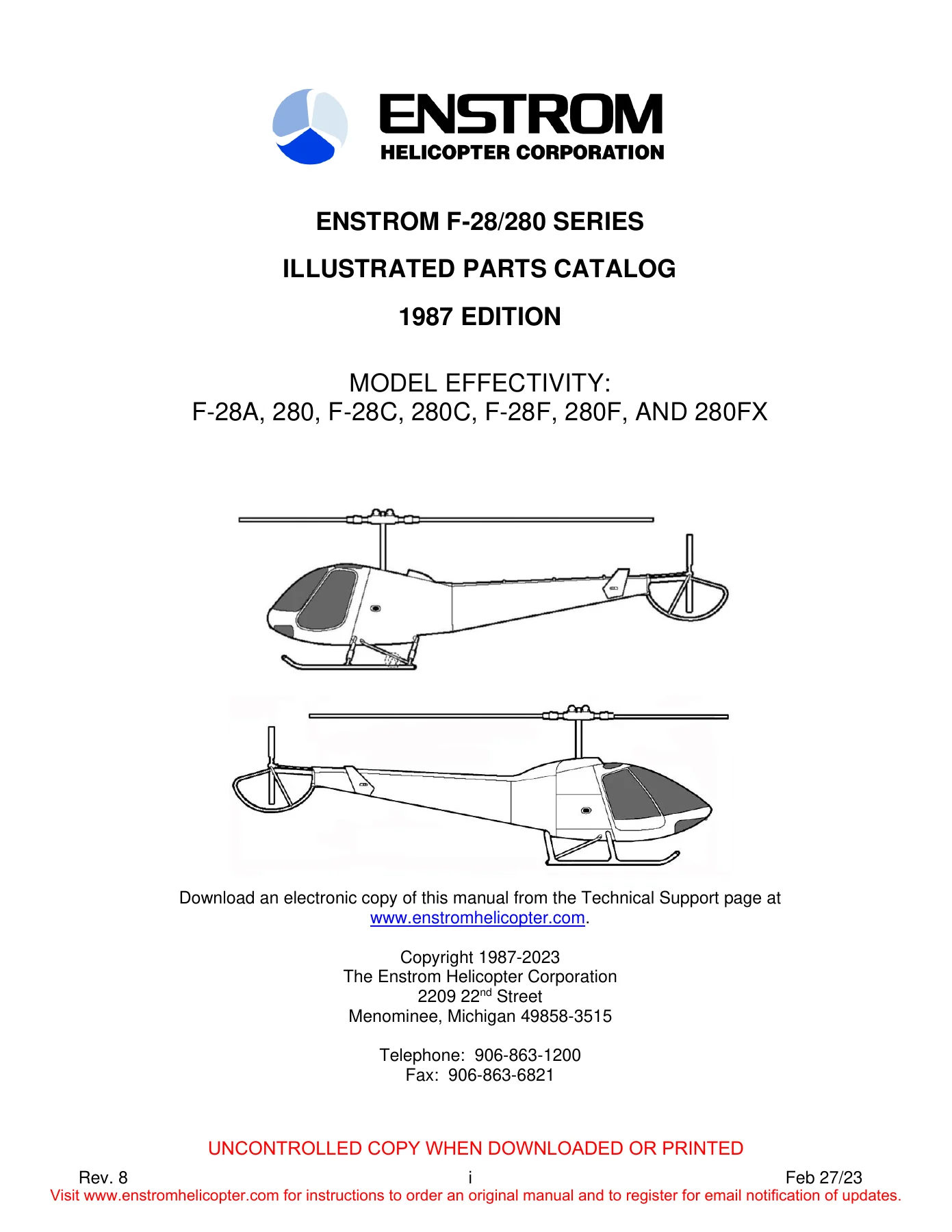
Enstrom F-28 and 280 Series Helicopter Illustrated Parts Catalog (F-28A, 280, F-28C, 280C, F-28F, 280F, 280FX)
Original price was: $39.95.$24.95Current price is: $24.95.
Comprehensive factory Illustrated Parts Catalog for the Enstrom F-28 and 280 series helicopters, covering models F-28A, 280, F-28C, 280C, F-28F, 280F, and 280FX. Features complete exploded-view diagrams, detailed parts lists, serial number effectivity, standard hardware substitution tables, and equivalent parts cross-references.
Description
Enstrom F-28 and 280 Series Helicopter Illustrated Parts Catalog (F-28A, 280, F-28C, 280C, F-28F, 280F, 280FX)
The Enstrom F-28 and 280 Series Helicopter Illustrated Parts Catalog (F-28A, 280, F-28C, 280C, F-28F, 280F, 280FX) is the definitive technical parts reference manual issued by The Enstrom Helicopter Corporation for maintenance personnel, operators, and aviation repair stations. Encompassing both naturally aspirated and turbocharged piston models across multiple production generations, this comprehensive manual provides complete definitions of all replacement parts, detail subassemblies, dynamic components, structural airframe elements, and installation hardware. Every illustrated breakdown is accompanied by manufacturer part numbers, standard hardware nomenclature, quantity requirements per assembly, and aircraft serial-number effectivity to guarantee accurate parts procurement and precise maintenance operations.
Document & File Details
- Manual Type: Illustrated Parts Catalog (IPC)
- Brand: Enstrom Helicopter Corporation
- Applicable Models: Enstrom F-28A, 280, F-28C, 280C, F-28F, 280F, and 280FX
- Publication Edition: 1987 Edition
- Latest Revision Level: Revision 8 / Revision 9 (through May 2023)
- Corporate Source: The Enstrom Helicopter Corporation, Menominee, Michigan, USA
- Language: English
- Page Count: 792 pages
- Document Features: Fully detailed exploded-view illustrations, numerical part indexes, standard hardware tables, and STC conversion data
- File Format: Portable Document Format (PDF)
Comprehensive Power Plant & Induction System Breakdown
Section 3 of the Enstrom F-28 and 280 Series Helicopter Illustrated Parts Catalog (F-28A, 280, F-28C, 280C, F-28F, 280F, 280FX) provides complete coverage of engine installations, mounting geometry, cooling airflow management, exhaust systems, and fuel delivery. The catalog details distinct air induction system configurations, separating the early F-28A atmospheric ducting from the refined air boxes and silicone/fiberglass ducting of the turbocharged 280C, F-28F, and 280FX airframes. Components cataloged include air filter assemblies (fram, foam inserts, and screen elements), adapter flanges, clamp configurations, and sealing boots. For turbocharged variants, the manual breaks down the complete turbocharger induction system, including turbo mount brackets, Rajay turbocharger units, blast tubes, heat-resistant turbo blankets, and bypass assemblies.
Exhaust system breakdowns clearly differentiate between naturally aspirated riser manifolds with cabin heat muffs and turbocharged exhaust systems featuring wastegate linkages, ball plungers, clevis pins, expansion joints, and optional exhaust muffler installations. Engine cooling management is thoroughly represented through multiple generations of engine fan shrouds, cooling fan assemblies, stator vanes, alternator blast cooling ducts, and starter shroud baffles accommodating Prestolite, B&C, and lightweight Skytec starters. Fuel plumbing is fully cataloged from the airframe tanks down to the Lycoming injector fuel servo, flow divider, fuel pressure sensor switches, booster pumps, fuel shutoff valve assemblies, and airframe-mounted fuel strainer and drain valves.
Main Rotor Hub, Dynamic Components & Rotor Drive
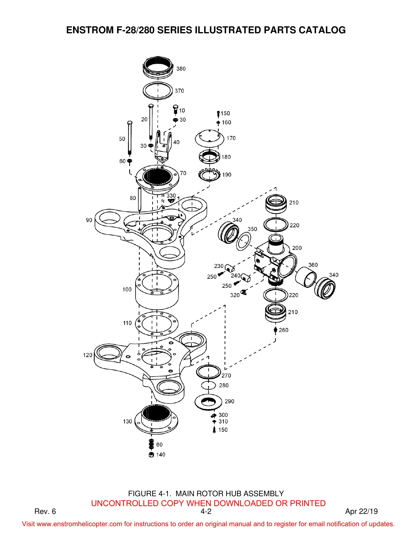
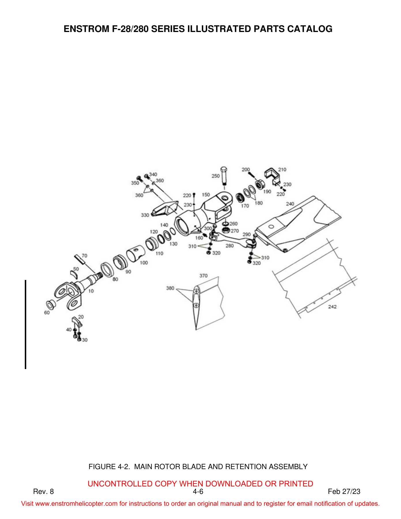
Section 4 and Section 5 provide comprehensive exploded views and numerical parts tracking for the core lifting and drive systems. The main rotor hub assembly is illustrated down to individual upper and lower hub plates, hub center spacers, universal block assemblies, needle bearings, flapping stop pads, flapping pins, and laminated alignment shims. The catalog includes complete breakdowns for the classic main rotor blade retention spindle assembly with its thrust bearing packs, drag links, blade grips, and retention pins, alongside dedicated coverage for modern retrofits including Supplemental Type Certificate (STC SR03465CH) tension-torsion (TT) strap retention conversions.
For vibration management and rotor blade lead-lag stability, the manual provides full component-level breakdowns for the hydraulic damper assemblies, including the P/N 28-14375-101 configuration. Technicians can reference exploded views of the damper cylinder housing, internal pistons, metering sleeves, relief valve capsules, wiper rings, high-pressure O-rings, and rod-end rod attachments. The belt drive transmission chapter details the belt tension actuator mechanism, spring housing assemblies, idler pulleys, jack struts, engagement control linkages, main rotor transmission gearbox mountings, and lower mast seal retainer assemblies.
Flight Controls, Tail Rotor Drive & Airframe Systems
Precision flight control linkages are fully detailed across Section 8, illustrating the entire cyclic and collective kinematic chain. Mechanics have instant access to part numbers for upper and lower swashplate assemblies, cyclic control sticks, torque shafts, reversing bellcranks, push-pull rods, collective friction clutches, and electric longitudinal and lateral trim actuator capsules. Section 12 complements the directional control system with exhaustive illustrations of the tail rotor transmission gearbox, intermediate hanger bearings, flexible driveshaft couplings, tail rotor pitch links, pitch change mechanisms for both right-hand and left-hand gearboxes, and multiple tail rotor blade assemblies across early ‘A’ models, ‘C’ models, and advanced ‘F’/’FX’ configurations.
Structural and interior systems are meticulously cataloged in Sections 6, 7, 9, 10, and 11. These sections cover the tubular pylon framework, tailcone bulkheads, skin panels, horizontal stabilizer extensions, oleo strut landing gear assemblies, aerodynamic fairings, cabin door hinges, bubble windows, cabin interior furnishings, restraint harnesses, cabin combustion and bleed heating ducts, and comprehensive instrument panel layouts spanning classic round-dial configurations up to contemporary electronic engine monitoring installations.
Chapters & Major Sections Covered
- Section 1 — Introduction: Scope of publication, revision methods, detailed parts list format, period/dot indentation system, and user change reporting procedures.
- Section 2 — Parts Ordering Information: Factory ordering instructions, dealer network coordination, AOG emergency handling, shipping criteria, and aircraft data plate location guidelines.
- Section 3 — Power Plant:
- Air Induction Systems (F-28A, 280, F-28C, 280C, F-28F, 280F, 280FX)
- Turbocharger Induction System & Blast Tube Routing
- Fuel Nozzle Air Vent System & Manifold Lines
- Engine Crankcase Breather Vent & Sniffer Valve Installation
- Magneto Cooling Shrouds & Silicone Duct Installations
- Oil Cooler Installations (Standard & Auxiliary Systems)
- Turbocharger Oil Supply, Scavenge Pump & Return Lines
- Engine Oil Fill Tube, Dipstick & Scupper Drain Assembly
- Throttle & Mixture Control Linkages (A and C Models)
- Throttle Correlator Assemblies & Cable Installation (F and FX Models)
- Dual Throttle Control Bellcranks & Tie Rods
- Firewall Curtain Assembly, Baffles & Perimeter Mounting Strips
- Engine Fan Shroud Assemblies (Generations A, C, F, and FX)
- Cooling Fan Disk, Stator Blades, Alternator Drive & Balancing Hardware
- Engine Fuel Plumbings, Boost Pumps & Fuel Pressure Transducers
- Main Airframe Fuel Tanks, Venting Lines & Sump Drain Hardware
- Fuel Level Sender Units & Fuel Quantity Sight Gauges
- Fuel Shutoff Cock Valve Disassembly & Remote Cockpit Cable Controls
- Exhaust Risers, Turbo Manifolds, Collectors & Cabin Heat Shrouds
- Wastegate Actuation Linkage, Plungers & Adjusting Rods
- Turbocharger Mount Tubular Structures & Engine Vibration Isolators
- Engine Accessory Interface Components & Ignition Harnesses
- Section 4 — Main Rotor System:
- Main Rotor Hub Center Section, Upper/Lower Hub Plates & Spacers
- Universal Blocks, Flapping Stop Pads & Trunnion Bearings
- Main Rotor Blade Grip, Retention Spindle & Thrust Bearing Assemblies
- STC SR03465CH Tension-Torsion (TT) Strap Retention Retrofit Assembly
- Flapping Pin Bushings, Retaining Nuts & Alignment Washers
- Hydraulic Lead-Lag Damper Assembly (28-14375-101 Series Breakdown)
- Main Rotor Blades, Trim Tabs & Balancing Tip Plugs
- Section 5 — Belt Drive Assembly:
- Drive Belt Tensioner Mechanism, Electric Actuator & Over-Travel Switches
- Belt Tension Spring Housing Assembly & Internal Preload Hardware
- Idler Pulley, Support Housing & Pivot Arm Assemblies
- Transmission Jack Strut, Guide Pulleys & Turnbuckle Brackets
- Main Rotor Drive Engagement Control Levers & Linkages
- Main Rotor Transmission Gearbox Mounting & Isolation Hardpoints
- Transmission Lower Mast Seal Retainer Assembly
- Section 6 — Electrical System: Circuit breaker panels, forward landing light assemblies, night flight lighting kits, position strobe beacons, 12-volt battery boxes, 24-volt electrical systems, annunciator relay panels, and electric pitch/roll trim circuitry.
- Section 7 — Structures: Forward cabin structure, pilot and copilot doors, door latch hardware, bubble windshield and door glazing, engine cowlings, 280FX three-piece airscoop, center pylon assembly, monocoque tailcone, horizontal stabilizer fins, tail rotor driveshaft tunnels, and skid landing gear with oleo shock struts.
- Section 8 — Flight Controls: Lower and upper swashplates, collective torque tubes, pilot/copilot collective sticks, cyclic control sticks, mixer bellcranks, push-pull control tubes, collective friction locks, and electrical trim bias spring assemblies.
- Section 9 — Furnishings: Cabin seating frameworks, upholstery cushions, soundproofing insulation, shoulder harness restraints, and cockpit fire extinguisher brackets.
- Section 10 — Utility Systems: Muffler heat muffs, cabin heating distribution ducts, flapper control valves, and firewall shutoff controls.
- Section 11 — Instruments: Flight and navigation instrument panels, pitot-static plumbing, turbine inlet temperature (TIT) gauges, graphic engine monitors, digital tachometer drives, and warning placards.
- Section 12 — Tail Rotor: 90-degree tail rotor gearbox transmission, hanger bearing supports, Thomas-coupling drive shafts, pedal control assemblies, control cables, pitch links, pitch change mechanisms, and tail rotor blades.
- Section 13 — Shims: Master thickness index and part numbering matrix for all airframe, rotor, and drive alignment shims.
- Appendix A — Equivalent Parts: Cross-reference catalog linking engineering part numbers with commercial aviation supplier designations.
- Appendix B — Standard Hardware Substitutions: Comprehensive engineering substitution tables covering AN, MS, and NAS bolts, machine screws, locknuts, nutplates, solid/blind rivets, washers, grommets, cotter pins, and cushioned clamps.
Together, these thirteen chapters and dual technical appendices provide aircraft maintenance technicians, aviation sheet metal specialists, and Enstrom helicopter owners with an indispensable engineering parts breakdown. By illustrating the relationship between high-level assemblies and individual internal components, the catalog eliminates guesswork during scheduled inspections, annual overhauls, major dynamic rebuilds, and routine component replacements.
Model Effectivity & Serial Number Tracking
Because Enstrom helicopters have evolved across decades of aerodynamic and mechanical refinement, this parts catalog incorporates meticulous model effectivity indicators across every single parts table. Specific columns and callout notes detail whether an individual part applies to the atmospheric F-28A and 280, the turbocharged F-28C and 280C, or the high-performance F-28F, 280F, and 280FX configurations. Serial number breakpoints are tracked down to individual airframes, highlighting critical transitions such as the relocation of the fuel strainer assembly on F-28F S/N 746 and 280FX S/N 2012, the introduction of upgraded starter shrouds for lightweight starters, tail rotor control revisions between left-hand and right-hand gearbox mountings, and the transition between different door latch and cabin door assemblies.
Essential Parts Catalog for Maintenance, Restoration & Procurement
Having access to the official Enstrom F-28 and 280 Series Helicopter Illustrated Parts Catalog (F-28A, 280, F-28C, 280C, F-28F, 280F, 280FX) is vital for maintaining the airworthiness, safety, and regulatory compliance of your rotorcraft. In aviation maintenance, ordering parts based on visual estimates or generic dimensions leads to costly downtime, incorrectly configured assemblies, and potential safety hazards. This manual provides the exact manufacturer part numbers, superseded references, and approved AN/MS/NAS hardware callouts required when ordering directly from Enstrom service centers or certified aviation distributors.
Delivered as a pristine, high-resolution digital PDF download, this manual is immediately accessible upon payment. It can be stored on your workshop computer, loaded onto an iPad or tablet for hands-on reference directly inside the hangar, or printed out in full or individual section binders. Protect your investment, streamline periodic inspections, and maintain your Enstrom helicopter to exacting factory standards with this complete, authoritative illustrated parts catalog.
Reviews
There are no reviews yet.