
Epiroc SmartROC D50 D55 D60 D65 Operation Manual – TIS0003617.001 PDF
Original price was: $29.95.$17.95Current price is: $17.95.
Complete English operation manual for the Epiroc SmartROC D50, D55, D60 and D65 rock drill rigs running RCS version 6.20. Covers controls, tramming, positioning, rod handling, drilling, shutdown, transport, daily maintenance and full technical data in a 124-page PDF.
Description
The Epiroc SmartROC D50 D55 D60 D65 Operation Manual is the full operator’s guide for the SmartROC D50, D55, D60 and D65 surface rock drill rigs running Epiroc Rig Control System (RCS) version 6.20. Released under document number TIS0003617.001 and dated 2021-07-05, this English-language PDF follows the machine’s own control layout rather than a generic textbook order, so every procedure maps directly to a lever, button or menu the operator actually uses.
File Details
- Manual type: Operation manual
- Brand: Epiroc
- Covered models: SmartROC D50, SmartROC D55, SmartROC D60, SmartROC D65
- Document number: TIS0003617.001
- Publication date: 2021-07-05
- Control system: RCS version 6.20
- Language: English (en-US)
- Page count: 124
- File format: PDF
Chapters Covered
- Introduction – safety first, RCS version, purpose of the publication, target group, feedback and contact information, access levels
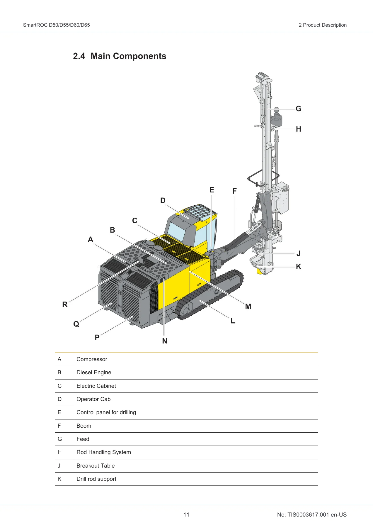
- Product Description – intended use, misuse of the product, data plate, main components, protective feed guard
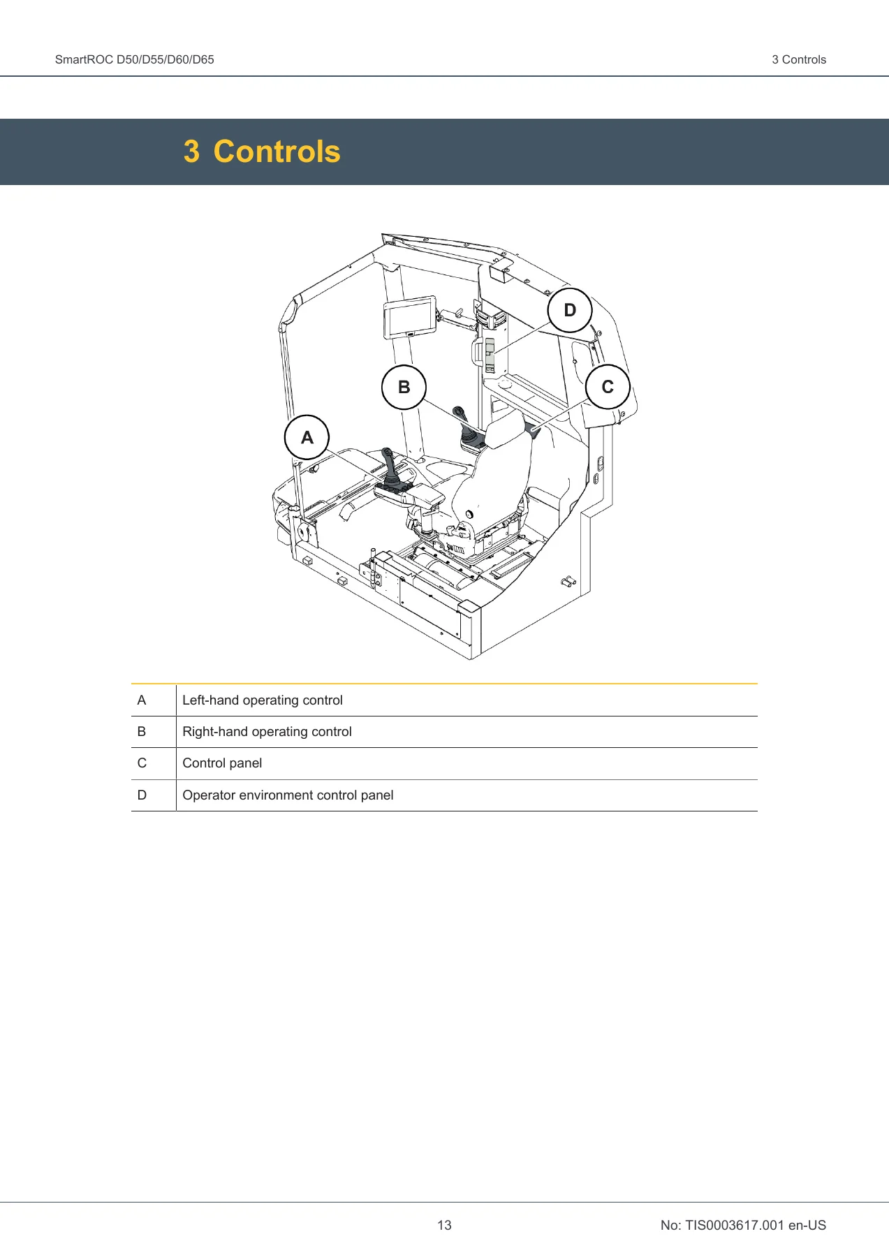
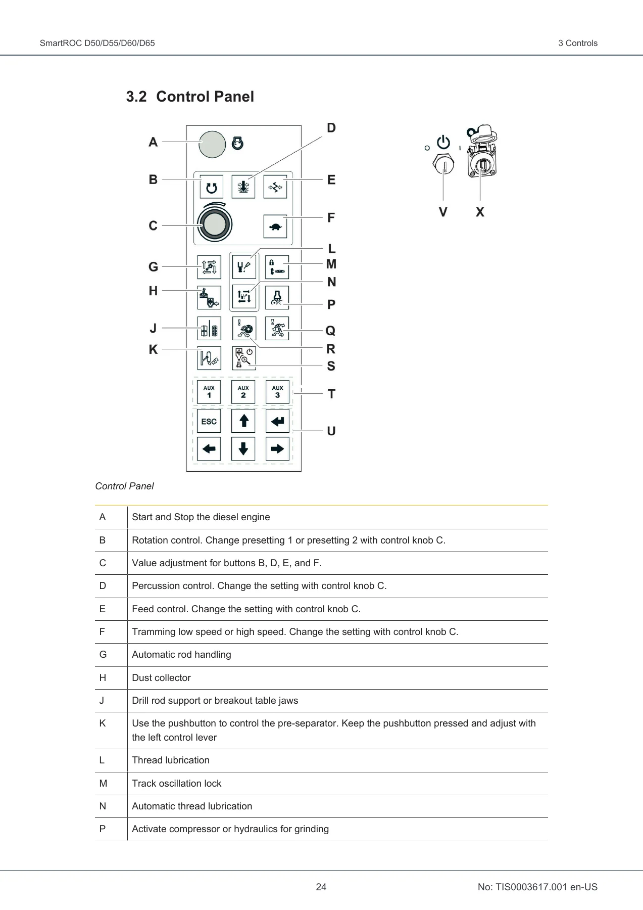
- Controls – operating controls, tramming levers, track oscillation levers, left lever in tram/positioning/drill mode, right lever in tram/positioning/drill mode, control panel, operator environment control panel
- Start and Stop the Control System – starting and stopping the control system
- Login Menu – logging in to a higher access level
- Display Settings – brightness, automatic menu change, units of measurement
- Operation – before startup, startup and shutdown, engine start protection, battery power on/off, starting and stopping the diesel engine, warming up the system, tramming, positioning, rod handling, drilling, service winch on feed
- Transport – preparations before hoisting, loading the machine onto a transport vehicle, hoisting a drill rig, before transporting the loaded drill rig
- Daily Maintenance – maintenance tables, visual check, washing the machine, emergency stops, work lights, fire suppression system, fire extinguishers, breakout table and drill rod support torques, compressor tank condensate, water separation filter, compressor oil level, dryer filter, diesel engine package, engine oil level, hydraulic tank, preliminary fuel filter, track frames, dust collector
- Technical Data – weight, ground pressure, performance, electrical system, air system, capacities, air conditioning unit, miscellaneous, dimensions, coverage area, feed swing angles, feed towards cab, maximum permitted inclination angles for tramming and machine setup
Working through this manual gives an operator a complete, machine-specific route from a cold rig to a drilled hole. It documents how the SmartROC D50 D55 D60 D65 control system is started and stopped, how each access level is unlocked, and how the display is configured before work begins. From there it explains the two hand levers in each of their modes, including the track oscillation, boom, feed and rod-handling functions assigned to each direction, plus the control panel and the operator environment panel that manage lighting, wipers, heating, air conditioning and the diesel engine. The operation chapter is the core of the book, covering a walk-around inspection, battery isolation, diesel engine start protection, hydraulic oil warm-up and the correct tramming and positioning techniques for level ground, uphill, downhill and across slopes. The drilling portion leads the reader through safety precautions, securing the floating adapter, drill settings, collaring and full-drilling, stopping, unthreading and retraction, adding a new drill pipe, changing a drill bit and the water mist system, followed by rod carousel loading and operation of the service winch on the feed.
Controls, Drilling and Machine Setup
Because the SmartROC rigs share a common control architecture, the lever diagrams in the Controls chapter are detailed enough to show what every direction, button and switch does in tram mode, positioning mode, drill mode, remote control mode and RC emergency mode. That includes hard grip and loose grip rod handling, drill steel support open and close, suction hood up and down, breakout table, carousel rotation, rapid feed, percussion, rotation, flush air, blow down, threading and unthreading. The positioning chapter then explains the aiming device, laser plane, GPS compass and drill plan handling, including how to calibrate the coverage area, load a drill plan template, add or remove holes and save a completed plan back to a USB stick.
Maintenance and Transport
The daily maintenance chapter is built around a calendar-time task table backed by a labelled visual check diagram, so a shift-start inspection can be worked through methodically: emergency stops, work lights, fire suppression system and extinguishers, breakout table and drill rod support torque values, compressor tank condensate, water separation filter, compressor oil level, dryer filter, diesel engine package, engine oil level, hydraulic tank, preliminary fuel filter, track frames and dust collector. The transport chapter covers hoisting preparations, positioning the boom, feed and rock drill for maximum stability, locking track oscillation and strapping the loaded rig to a trailer. Technical data at the end gives weights, ground pressure, engine output figures, tramming speeds, electrical system values, air system pressures and free air delivery, fluid capacities and the maximum permitted inclination angles for each feed configuration.
Who This Operation Manual Is For
This is the document for the operator who needs the correct startup sequence, the right lever function at the right moment and the accurate setting before a hole is collared. It also serves as a reference for supervisors, trainers and maintenance planners who need the manufacturer’s own procedures and daily check intervals for the SmartROC D50, D55, D60 and D65 in one place. Because the same rigs appear across different feed lengths and engine packages, the technical data and inclination angle tables are split by model and by Short Feed, Long Feed and XL Feed configuration, so the correct values can be found for the exact machine on site.
What You Can Do With It
With this manual to hand, an operator can start the SmartROC D50 D55 D60 D65 correctly, warm the hydraulic system in cold weather, tram and set up the rig within its permitted inclination limits, load and unload the rod carousel safely, drill and finish a hole, change a drill bit and shut the machine down without risking damage to the diesel exhaust fluid system. It supports the decisions that matter on a drilling site – which speed to tram at, how far the boom can swing, how much pressure the percussion circuit should see, how much torque the breakout table brackets should carry – using the numbers Epiroc published for these rigs rather than guesswork. It also gives a new operator a structured way to learn the control system and the RCS menus before touching the machine.
IMAGES PREVIEW
The Epiroc SmartROC D50 D55 D60 D65 Operation Manual is delivered as an instant PDF download. There is no shipping and no waiting – the file is available immediately after payment, opens on any computer, tablet or smartphone, and can be printed for the cab or the workshop. Keep a copy on the rig, on the office server and on a USB stick, and search the document by chapter whenever a procedure or a setting needs to be checked.
Reviews
There are no reviews yet.