
Description
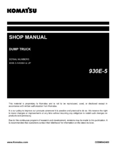
Komatsu 930E-5 Dump Truck Shop Manual – Serial A40004 and Up
The Komatsu 930E-5 Dump Truck Shop Manual is the workshop reference for the 930E-5 electric drive haul truck from serial number A40004 and up, powered by the Komatsu SSDA16V160 engine. Published under form number CEBM032201 by Komatsu America Corp, this shop manual walks the technician through every major system on the truck: steering circuit, hoist circuit, brake circuits, the 24-volt electrical system, cab air conditioning, the automatic lubrication (auto lube) system, and the Tier 4 Final / Stage IV engine emissions after-treatment system with selective catalytic reduction.
Because the 930E-5 is a large electric-drive mining truck, the depth of coverage matters more than the size of the book. This manual supplies that depth: component-level structure and function, standard value tables, testing and adjusting procedures with data sheets, fault code troubleshooting, and full hydraulic and electrical schematics.
File Details
- Manual type: Shop Manual (workshop service, structure, testing and diagnostics)
- Brand / Publisher: Komatsu America Corp
- Machine model: 930E-5 Dump Truck
- Serial number range: 930E-5 A40004 and up
- Engine: 16V160 (Komatsu SSDA16V160)
- Form number: CEBM032201
- Language: English
- File format: PDF
- Page count: 861 pages
Chapters Covered
- 00 Index and foreword β Foreword and how to read the shop manual; general safety; precautions before and while operating; working near batteries; precautions before and while performing service; tires; precautions for repairs; control cabinet capacitor discharge system; welding on the truck; handling electrical equipment and hydraulic components; actions taken to meet exhaust gas regulations; precautions for DEF; standard tightening torques; conversion tables
- 01 Specification β Specification drawing, specifications, weight table, fuel / coolant / lubricants
- 10 Structure and functions β Steering circuit (operation, components, steering/brake pump, flow amplifier); hoist circuit (operation, components, hoist pilot valve); brake circuits (general, service brake, parking brake, wheel brake lock, brake warning); electrical system 24V (battery supply, isolation box, engine starting with prelube, auxiliary control cabinet, body-up switch, hoist limit switch); cab air conditioning; automatic lubrication system; engine emissions after-treatment system
- 20 Standard value table β Standard value table for truck
- 30 Testing and adjusting β Steering, hoist, brake cooling and auxiliary hydraulic systems; brake system; accumulators and suspensions; electrical systems; Interface Module (IM); KOMTRAX Plus II; Payload Meter IV; Komatsu Wireless Bridge (KWB); cab air conditioning; automatic lubrication system; KomVision
- 40 Troubleshooting β Fuse, diode and relay locations (VEC-89, VEC-90, VEC-91, VEC-92, RTMR3, RTMR4, circuit breakers); troubleshooting by fault code Parts 1 through 5 (fault codes A001 through A447); steering system troubleshooting; KomVision fault codes
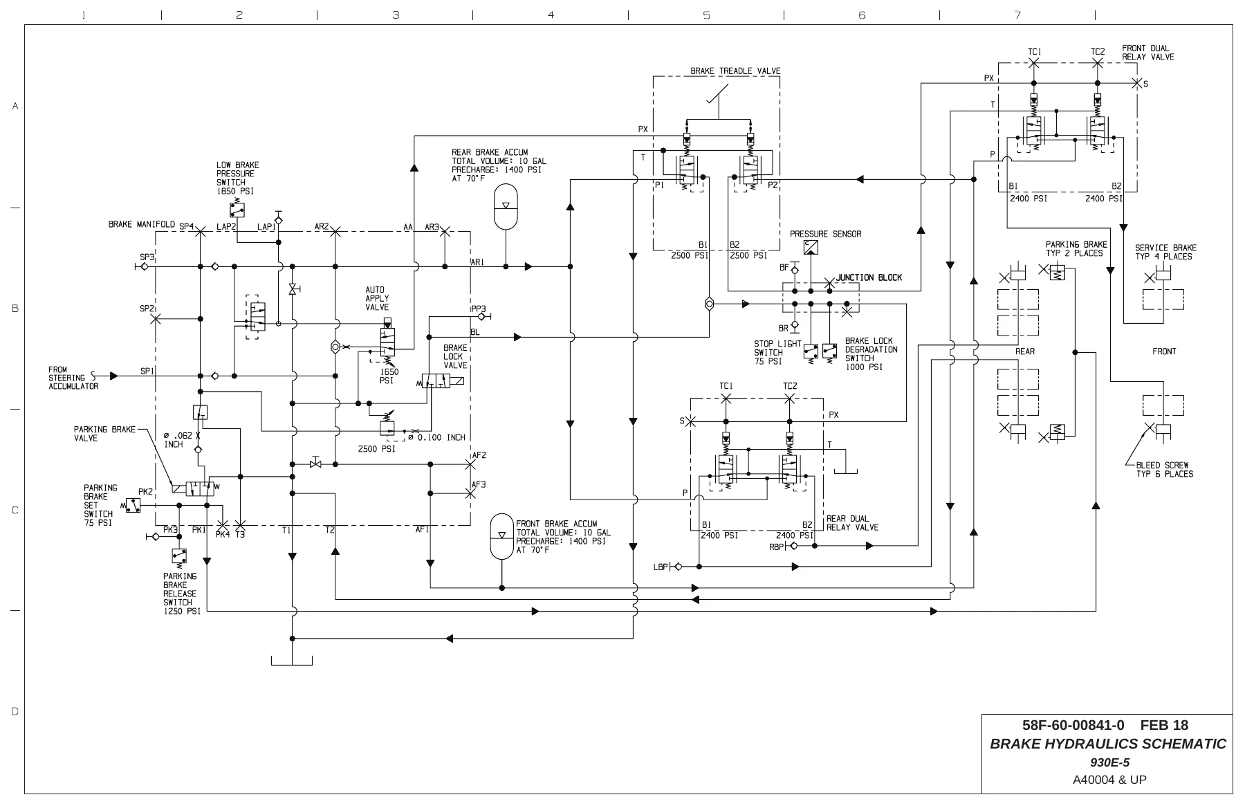
- 90 Diagrams and drawings β Hydraulic circuit diagrams (steering, hoist and brake cooling schematic; brake hydraulic schematic; auxiliary system schematic) and electrical circuit diagrams (main electrical schematic; electrical sub-system schematic)
What makes this Komatsu 930E-5 shop manual genuinely usable in the shop is that the sections are built to work together. Structure and functions explains how the system is supposed to behave. Standard value table fixes the numbers. Testing and adjusting tells you how to measure them. Troubleshooting by fault code closes the loop with a clear path from symptom to component. The 90 Diagrams and drawings section then delivers the schematics needed to trace a circuit or hydraulic line end to end.
Systems and Subsystems Documented
The 930E-5 workshop manual goes well past a general overview. Each of the following systems is covered with its own operation description, components, and testing procedures:
Complete PDF Bookmark Tree
Complete Bookmarks
The complete bookmarks in the βKomatsu 930E-5 Dump Truck Shop Manual – Serial A40004 & Upβ are as follows:
+00 Index and forewordp. 3
+Indexp. 3
Composition of shop manualp. 4
Table of contentsp. 6
+Foreword, safety and general informationp. 17
Forewordp. 20
+How to read the shop manualp. 21
Composition of shop manualp. 21
Revision and distributionp. 21
Symbolsp. 22
+General safetyp. 23
Safety rulesp. 23
Safety featuresp. 23
Fire extinguisher and first aid kitp. 23
Clothing and personal itemsp. 23
Leaving the operator seatp. 24
Mounting and dismountingp. 24
Fire prevention for fuel and oilp. 24
Precautions with high temperature fluidsp. 25
Asbestos dust hazard preventionp. 25
Prevention of injury by work equipmentp. 25
Unauthorized modificationp. 25
Precautions when using ROPSp. 25
Precautions for attachmentsp. 26
Precautions for starting the truckp. 26
+Precautions before operating the truckp. 26
Safety at the worksitep. 26
Fire preventionp. 27
Ventilation in enclosed areasp. 27
Preparing for operationp. 27
Mirrors, windows and lightsp. 27
In operator cab (before starting the engine)p. 27
Seat Beltsp. 27
+Precautions while operating the truckp. 28
When starting the enginep. 28
General truck operationp. 28
Ensuring good visibilityp. 28
Travelingp. 29
Traveling in reversep. 29
Traveling on slopesp. 29
Operating on snow or icep. 29
Avoid damage to dump bodyp. 29
Driving near high voltage cablesp. 30
When dumpingp. 30
When loadingp. 30
Working on loose groundp. 30
Parking the truckp. 30
Towingp. 30
+Working near batteriesp. 31
Battery hazard preventionp. 31
Starting with jumper cablesp. 32
Jump starting with receptaclesp. 32
+Precautions before performing servicep. 33
Warning tagp. 33
Stopping the enginep. 33
Proper toolsp. 33
Use of Tie-Off Anchor During Maintenance and Repairp. 33
Securing the dump bodyp. 34
Jack point locationsp. 35
+Precautions while performing servicep. 36
Keep the truck cleanp. 36
Attachmentsp. 36
Working under the truckp. 36
Rotating fan and beltsp. 36
Adding fuel or oilp. 36
Use of lightingp. 36
Radiator coolant levelp. 37
Precautions with the batteryp. 37
Precautions with high pressure oilp. 37
Handling high pressure hosesp. 37
Precautions when performing maintenance near high temperature or high pressurep. 37
Waste materialsp. 37
+Tiresp. 38
Inspectionp. 38
Maintenancep. 38
Storagep. 39
Handlingp. 40
+Precautions for performing repairsp. 41
Engine shutdown procedure after AC drive system failurep. 41
Precautions for welding on the truckp. 42
Control cabinet capacitor discharge systemp. 43
+Handling electrical equipment and hydraulic componentsp. 45
Points to remember when handling electrical equipmentp. 45
Points to remember when handling hydraulic equipmentp. 51
+Actions taken to meet exhaust gas regulationsp. 53
+Precautions for DEFp. 54
General character and precautions for handlingp. 54
Precautions for addingp. 54
Precautions for storingp. 54
Precautions for fire hazard and leakagep. 54
Other precautionsp. 54
Store AdBlue/DEFp. 55
Handling AdBlue/DEF in cold weatherp. 55
+Standard tightening torquesp. 56
Effect of special lubricants on fasteners and standard torque valuesp. 56
Suggested sources for rust preventive greasep. 56
SAE grade 5 and grade 8 hex head capscrew and nut assembliesp. 57
SAE grade 9 capscrewsp. 58
Class 10.9 capscrews and class 10 nutsp. 58
Standard tightening torques for fittingsp. 59
Standard tightening torques for clampsp. 61
+Conversion tablesp. 62
Common conversion multipliersp. 62
+01 Specificationp. 67
+Specification and technical datap. 67
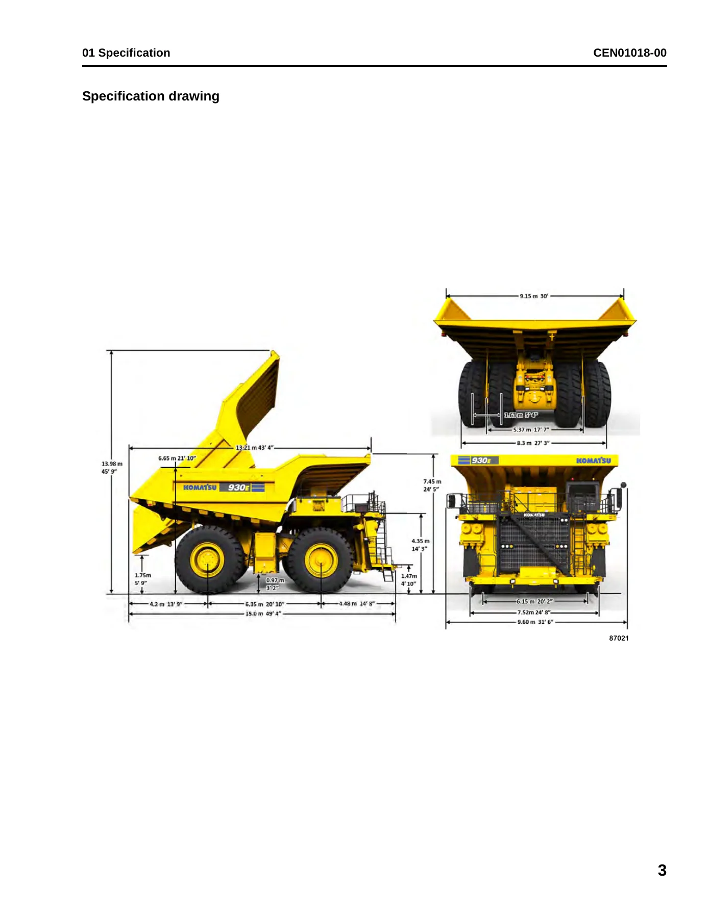
Specification drawingp. 69
Specificationsp. 70
Weight tablep. 72
+Fuel, coolant and lubricantsp. 73
Suspension cylinder oil and nitrogen specificationsp. 74
+10 Structure and functionsp. 77
+Steering circuitp. 77
Steering circuit operationp. 78
+Steering circuit componentsp. 83
Steering control unitp. 83
High pressure filterp. 83
Steering accumulatorsp. 83
Bleeddown manifoldp. 84
Steering accumulator bleeddown solenoidp. 84
Quick disconnect portsp. 84
Flow amplifierp. 84
+Steering/brake pump operationp. 85
High altitude operationp. 85
Neutral positionp. 86
Full pump volumep. 87
Half pump volumep. 87
+Flow amplifier operationp. 88
No steerp. 88
Steering leftp. 90
Steering rightp. 92
No steer, external shock loadp. 94
+Hoist circuitp. 97
Hoist circuit operationp. 98
+Hoist circuit componentsp. 98
Hydraulic tankp. 98
Hoist pumpp. 98
High pressure filtersp. 98
Hoist valvep. 101
Inlet sectionsp. 101
Tank ports (front) spool sectionp. 101
Work ports (rear) spool sectionp. 102
Hoist pilot valvep. 102
Hoist limit solenoidp. 103
Pilot operated check valvep. 103
Overcenter manifoldp. 103
+Hoist pilot valve operationp. 104
Float position with body downp. 104
Power up operationp. 106
Hold operationp. 108
Power down operationp. 110
Float operation with body upp. 112
+Brake circuitsp. 115
General informationp. 117
Service brake circuit operationp. 119
Secondary braking and auto applyp. 120
+Parking brake circuit operationp. 121
Normal operation (key switch ON, engine on)p. 121
Wheel brake lock circuit operationp. 122
Brake warning circuit operationp. 122
+Electrical system, 24 voltp. 125
+Battery supply systemp. 127
Batteriesp. 127
24VDC auxiliary battery receptaclesp. 127
+Isolation boxp. 128
Ground level shutdown switchp. 128
Battery disconnect switchesp. 128
Propel lockout leverp. 128
System busy lightp. 128
LED lightsp. 128
+Engine starting system with prelubep. 129
+Auxiliary control cabinet componentsp. 130
VEC blocksp. 131
24VDC to 12VDC converterp. 131
Circuit breakersp. 131
Engine service light timerp. 131
Ground terminalsp. 131
24VDC power terminalsp. 131
Relaysp. 132
Body-up switchp. 133
Hoist limit switchp. 134
+Cab air conditioningp. 137
+General informationp. 138
Environmental impact of air conditioningp. 138
Air conditioning for off-highway vehiclesp. 138
+Principles of refrigerationp. 139
Air conditioningp. 139
Refrigeration – the act of coolingp. 139
The refrigeration cyclep. 139
+Air conditioning system componentsp. 141
ECU modulep. 141
Fan motor and speed controlp. 141
Cab air filterp. 141
Heater corep. 141
Actuatorsp. 141
Compressor (refrigerant pump)p. 142
Service valvesp. 143
Condenserp. 143
Receiver-drierp. 143
Accumulatorp. 143
Expansion valvep. 144
Evaporator corep. 144
+Air conditioning system electrical circuitp. 145
Thermostatp. 145
Compressor clutchp. 145
Trinaryβ’ switchp. 146
+Automatic lubrication (auto lube) systemp. 149
General informationp. 150
System operationp. 151
+Engine emissions after-treatment systemp. 155
Selective catalytic reduction (SCR)p. 157
DEF injection systemp. 157
Sensorsp. 158
DEF heating systemp. 158
Inducement strategyp. 158
+20 Standard value tablep. 161
+Standard value tablep. 161
Standard value table for truckp. 163
+30 Testing and adjustingp. 169
+Steering, hoist, brake cooling and auxiliary hydraulic systemsp. 169
Hydraulic system bleeddown procedurep. 171
General information on system checkoutp. 173
+Hydraulic system checkout proceduresp. 173
Required equipmentp. 173
Bleeddown procedurep. 173
Preliminary stepsp. 176
Hydraulic system flushing procedurep. 177
Flow amplifier adjustmentp. 180
Steering pump unloader valve adjustmentp. 181
Auxiliary accumulator pressure verificationp. 182
System diagnosticsp. 182
Hoist pilot relief valve adjustmentp. 185
Hoist counterbalance valve adjustmentp. 185
Final stepsp. 186
Oil cleanliness checkp. 186
Hydraulic system checkout data sheetp. 187
Toe-in adjustmentp. 190
Hoist cylinder leakage testp. 191
Steering cylinder leakage testp. 191
+Brake systemp. 193
General information on system checkoutp. 195
+Brake system checkout proceduresp. 195
Required equipmentp. 195
Bleeddown procedurep. 195
Preliminary stepsp. 198
Service brake checkout (front and rear)p. 199
Brake lock system checkoutp. 200
Low brake pressure and auto apply checkoutp. 200
Service brake checkout (left and right)p. 202
Parking brake checkoutp. 203
Parking brake control logic checkoutp. 203
Brake lock control logic checkoutp. 205
Brake system checkout data sheetp. 208
Brake piston leakage testp. 217
Brake seal pressure testp. 217
Oil separator seal pressure testp. 217
Wet disc brake bleeding procedurep. 218
Parking brake bleeding procedurep. 219
Service brake disc wear inspectionp. 220
Parking brake disc wear inspectionp. 221
+Accumulators and suspensionsp. 223
+Accumulator charging and storagep. 224
Temperature during prechargep. 224
+Bladder accumulator charging procedurep. 225
Precharge maintenancep. 227
Bladder accumulator storage procedurep. 227
Bladder storagep. 227
Installing a bladder accumulator from storagep. 228
Bladder accumulator leak testingp. 228
Piston accumulator charging procedurep. 229
Piston accumulator storagep. 232
Piston accumulator leak testingp. 232
Checking for improper suspension chargep. 233
+Suspension oiling and charging proceduresp. 234
Required equipmentp. 234
Installing the charging kitp. 235
Removing the charging kitp. 235
Support blocks for oiling and charging dimensionsp. 236
Front suspensionsp. 237
Rear suspensionsp. 240
Suspension pressure testp. 243
+Electrical systemsp. 245
General information on system checkoutp. 247
Truck shutdown procedurep. 248
Required software and toolsp. 248
+Electrical system checkout proceduresp. 250
Visual inspectionp. 250
Resistance checksp. 250
Voltage checksp. 250
Truck function checksp. 251
Interface module (IM) checksp. 252
KOMTRAX Plus II checksp. 252
Payload meter (PLM) checksp. 252
Drive system checksp. 253
Engine delayed shutdown Smart Timer checkp. 253
Body hoist limit switch checkp. 253
Electrical checkout sheetp. 254
+Interface module (IM)p. 259
Required software and toolsp. 261
+Interface module checkout proceduresp. 262
Initial startupp. 262
Checking digital inputs to the IMp. 262
Checking analog inputs to the IMp. 264
Checking serial communication to the IMp. 264
Checking outputs from the IMp. 265
IM checkout sheetp. 266
+KOMTRAX Plus IIp. 271
Required software and toolsp. 273
Ethernet connection to KOMTRAX Plus II controllerp. 273
KOMTRAX Plus II configurationp. 275
GPS connection testp. 277
Iridium satellite system openingp. 279
Data download over ethernet connection for KOMTRAX Plus II initializationp. 281
+Payload meter IVp. 285
Payload meter IV software and toolsp. 286
+Payload meter IV system configurationp. 286
Connecting to the payload meter IV web serverp. 286
Configuring a static IP addressp. 286
Payload meter IV software installationp. 288
Payload meter IV checkout procedurep. 289
PLM IV system checkout data sheetp. 293
+Komatsu wireless bridge (KWB)p. 295
General informationp. 296
Required software and toolsp. 296
Configuring the Bullet wireless radiop. 297
Installing the Bullet wireless radiop. 300
Configuring the NanoStation access pointp. 301
Testing the connectionp. 304
Changing a service computerβs IP addressp. 305
+Cab air conditioningp. 307
General informationp. 309
+Service tools and equipmentp. 310
Recovery/recycle stationp. 310
Leak detectorp. 310
Manifold gauge setp. 311
Service valvesp. 312
Vacuum pumpp. 312
Detecting leaksp. 313
System performance testp. 314
Checking system oilp. 315
System flushingp. 316
+Installing the manifold gauge setp. 317
Purging air from the service hosesp. 317
+Recovering and recycling refrigerantp. 318
Draining oil from previous recovery cyclep. 319
Recovery cyclep. 319
Recycling procedurep. 319
Evacuating the air conditioning systemp. 320
Charging the air conditioning systemp. 321
+Automatic lubrication (auto lube) systemp. 323
Priming the systemp. 325
Checkout procedurep. 326
Adjusting the lubrication cycle timingp. 327
+KomVisionp. 329
Requirementsp. 330
Initial setupp. 331
KomVision checkout data sheetp. 338
+Calibration sheetsp. 343
Layout and assemblagep. 343
Unfolding a calibration sheetp. 346
Folding a calibration sheetp. 347
Placement of calibration sheetsp. 348
+Camera calibration proceduresp. 350
Automatic 6 camera calibrationp. 350
Manual 6 camera calibrationp. 354
1 camera calibrationp. 357
Radar setting procedurep. 360
+40 Troubleshootingp. 365
+Fuse, diode and relay locationsp. 365
Vehicle Electrical Center (VEC-89)p. 366
Vehicle Electrical Center (VEC-90)p. 368
Vehicle Electrical Center (VEC-91)p. 370
Vehicle Electrical Center (VEC-92)p. 372
Rear Terminal Mini-fuse and Relay (RTMR3)p. 373
Rear Terminal Mini-fuse and Relay (RTMR4)p. 374
Circuit breakersp. 374
+Troubleshooting by fault code, Part 1p. 377
Fault Code A001: Left front suspension pressure sensor signal highp. 380
Fault Code A002: Left front suspension pressure sensor signal lowp. 382
Fault Code A003: Right front suspension pressure sensor signal highp. 384
Fault Code A004: Right front suspension pressure sensor signal lowp. 386
Fault Code A005: Left rear suspension pressure sensor signal highp. 388
Fault Code A006: Left rear suspension pressure sensor signal lowp. 390
Fault Code A007: Right rear suspension pressure sensor signal highp. 392
Fault Code A008: Right rear suspension pressure sensor signal lowp. 394
Fault Code A011: Payload meter speed sensor signal has failedp. 396
Fault Code A013: Body up switch has failedp. 398
Fault Code A014: Payload meter checksum computation has failedp. 400
Fault Code A016: A payload meter write to flash memory has failedp. 401
Fault Code A017: A payload memory flash memory read has failedp. 402
Fault Code A018: Right rear flat suspension cylinder warningp. 404
Fault Code A019: Left rear flat suspension cylinder warningp. 406
Fault Code A022: Carryback load excessivep. 408
Fault Code A101: High pressure detected across a hydraulic pump filterp. 410
Fault Code A103: Hydraulic Oil Temp – Tank Sensor Lowp. 412
Fault Code A104: Hydraulic Oil Temp – Tank Sensor Highp. 413
Fault Code A105: Fuel level sensor shorted to ground, indicating a false high fuel levelp. 414
Fault Code A109: GE has generated a propel system reduced level signalp. 416
Fault Code A111: Low steering pressure warningp. 418
Fault Code A115: Low steering precharge pressure detectedp. 420
Fault Code A117: Low brake accumulator pressure warningp. 422
Fault Code A118: Brake pressure is low while in brake lockp. 424
Fault Code A123: GE has generated a reduced retarding cautionp. 426
Fault Code A124: GE has generated a no propel / no retard or system not running inputp. 428
Fault Code A125: GE has generated a no propel warningp. 432
Fault Code A126: Oil level in the hydraulic tank is lowp. 434
Fault Code A127: IM-furnished +5 volt output for sensors is lowp. 435
Fault Code A128: IM-furnished +5 volt output for sensors is highp. 436
Fault Code A139: Low fuel warningp. 438
+Troubleshooting by fault code, Part 2p. 441
Fault Code A145: Hydraulic temperature sensors cause advance of engine rpm to advance level 1 for cooling of hydraulic oilp. 444
Fault Code A146: Hydraulic temperature sensors cause advance of engine rpm to advance level 2 for cooling of hydraulic oilp. 446
Fault Code A152: Starter failurep. 448
Fault Code A153: Battery voltage is low with the truck in operationp. 450
Fault Code A154: Battery charging voltage is excessivep. 454
Fault Code A155: Battery charging voltage is lowp. 456
Fault Code A158: Fuel level sensor is open or shorted high, indicating a false low fuel levelp. 458
Fault Code A166: Left rear hydraulic oil temperature sensor is lowp. 460
Fault Code A167: Right rear hydraulic oil temperature sensor is lowp. 462
Fault Code A168: Left front hydraulic oil temperature sensor is lowp. 464
Fault Code A169: Right front hydraulic oil temperature sensor is lowp. 466
Fault Code A170: Left rear hydraulic oil temperature sensor is highp. 468
Fault Code A171: Right rear hydraulic oil temperature sensor is highp. 469
Fault Code A172: Left front hydraulic oil temperature sensor is highp. 470
Fault Code A173: Right front hydraulic oil temperature sensor is highp. 471
Fault Code A184: The J1939 data link is not connectedp. 472
Fault Code A190: The auto lube control has detected an incomplete lube cyclep. 474
Fault Code A193: Hydraulic Tank Oil Temperature is highp. 477
Fault Code A194: Left front hydraulic oil temperature is highp. 478
Fault Code A195: Right front hydraulic oil temperature is highp. 480
Fault Code A196: Left rear hydraulic oil temperature is highp. 482
Fault Code A197: Right rear hydraulic oil temperature is highp. 484
Fault Code A198: Hoist Pressure 1 Sensor is highp. 486
Fault Code A199: Hoist Pressure 2 Sensor is highp. 487
Fault Code A200: Steering Pressure Sensor Highp. 488
Fault Code A201: Brake Pressure Sensor Highp. 489
Fault Code A202: Hoist Pressure 1 Sensor Lowp. 490
Fault Code A203: Hoist Pressure 2 Sensor Lowp. 492
Fault Code A204: Steering Pressure Sensor Lowp. 494
Fault Code A205: Brake Pressure Sensor Lowp. 496
Fault Code A206: Ambient Temperature Sensor Highp. 498
Fault Code A207: Ambient Temperature Sensor Lowp. 499
Fault Code A213: The parking brake should have applied but is detected as not having appliedp. 500
Fault Code A214: The parking brake should have released but is detected as not having releasedp. 504
Fault Code A215: Brake auto apply valve circuit is defectivep. 510
Fault Code A216: An open or short to ground has been detected in the park brake command valve circuitp. 514
Fault Code A223: Excessive engine cranking has occurred or a jump start has been attemptedp. 518
Fault Code A230: Park brake has been requested while truck still movingp. 522
Fault Code A231: The body is up while traveling or intending to travelp. 526
Fault Code A233: Drive system CAN/RPC Control Link not connectedp. 530
Fault Code A235: Steering accumulator is in the process of being bled downp. 534
Fault Code A236: The steering accumulator has not properly bled after 90 secondsp. 538
Fault Code A237: The CAN/RPC connection to the Display is openp. 541
Fault Code A240: The keyswitch input to the Interface Module is openp. 542
Fault Code A242: The fuel gauge within the display panel is defectivep. 543
Fault Code A243: The engine coolant temp gauge within the display panel is defectivep. 544
Fault Code A244: Drive system temperature gauge within the dash display panel is defectivep. 545
Fault Code A245: The hydraulic oil temp gauge within the display panel is defectivep. 546
Fault Code A246: PLM reports truck overloadp. 547
+Troubleshooting by fault code, Part 3p. 549
Fault Code A247: Low steering pressure warningp. 552
Fault Code A248: Status module within the dash display panel is defectivep. 554
Fault Code A249: Red warning lamp within the dash display (driven by IM) is shortedp. 556
Fault Code A250: Battery voltage is low with the truck parkedp. 558
Fault Code A251: Sonalert used with the dash display (driven by IM) is open or shorted to groundp. 562
Fault Code A252: Start enable output circuit is either open or shorted to groundp. 564
Fault Code A253: Steering bleed circuit is not open while runningp. 566
Fault Code A256: Red warning lamp in the dash display (driven by IM) is openp. 568
Fault Code A257: Payload CAN/RPC is not connectedp. 570
Fault Code A258: Steering accumulator bleed pressure switch circuit is defectivep. 572
Fault Code A260: Parking brake failurep. 574
Fault Code A261: Low brake accumulator pressure warningp. 578
Fault Code A262: Steering bleed valve circuit open during shutdownp. 580
Fault Code A264: Parking brake relay circuit is defectivep. 584
Fault Code A265: Service brake failurep. 586
Fault Code A266: Shift lever was not in park while attempting to crank enginep. 588
Fault Code A267: Parking brake was not set while attempting to crank enginep. 590
Fault Code A268: Secondary engine shutdown while crankingp. 592
Fault Code A270: Brake lock switch power supply is not on when requiredp. 594
Fault Code A272: Brake lock switch power supply is not off when requiredp. 598
Fault Code A273: A fault has been detected in the hoist or steering pump filter pressure switch circuitp. 602
Fault Code A274: A brake setting fault has been detectedp. 604
Fault Code A275: A starter has been detected as engaged without a cranking attemptp. 606
Fault Code A277: Parking brake applied while loadingp. 608
Fault Code A278: Service brake applied while loadingp. 610
Fault Code A279: Low Steering Pressure Switch badp. 612
Fault Code A280: Steering accumulator bleed down switch is defectivep. 614
Fault Code A281: Brake lock degrade switch is defectivep. 616
Fault Code A282: The number of excessive cranking counts and jump starts without the engine running has reached 7p. 618
Fault Code A283: An engine shutdown delay was aborted because the parking brake was not setp. 622
Fault Code A284: An engine shutdown delay was aborted because the secondary shutdown switch was operatedp. 626
Fault Code A285: The parking brake was not set when the keyswitch was turned offp. 628
Fault Code A286: A fault was detected in the shutdown delay relay circuitp. 630
Fault Code A292: The shutdown delay relay has remained on after the latched key switch circuit is offp. 632
+Troubleshooting by fault code, Part 4p. 635
Fault Code A303: Shift lever is defectivep. 638
Fault Code A304: Auto lube grease level faultp. 640
Fault Code A305: Auto lube circuit is defectivep. 641
Fault Code A307: Both GE inverters are disabledp. 642
Fault Code A309: No brakes applied when expectedp. 644
Fault Code A310: Low fuel warningp. 646
Fault Code A311: Brake lock switch is on when it should not bep. 648
Fault Code A312: DC-DC converter 12 volt circuit sensing is producing low readingsp. 650
Fault Code A313: DCDC converter 12 volt circuit sensing is producing high readingsp. 651
Fault Code A315: DCDC converter 12 volt circuit is lowp. 652
Fault Code A316: Starter engagement has been attempted with engine runningp. 654
Fault Code A317: Operation of brake auto apply circuit without a detected responsep. 656
Fault Code A318: Unexpected power loss to interface modulep. 658
Fault Code A328: Drive system not powered upp. 659
Fault Code A332: Seat belt not buckledp. 660
Fault Code A333: The hydraulic ladder controller has declared a ladder faultp. 662
Fault Code A334: Selector switch not in park when propel was either not ready or at restp. 664
Fault Code A337: Engine Air Filter Circuit Faultp. 666
Fault Code A338: Engine Air Filter Faultp. 667
Fault Code A339: The diesel exhaust fluid level gauge within the display panel is defectivep. 668
Fault Code A340: The shifter controller has declared a faultp. 669
Fault Code A341: The shifter control circuit is defectivep. 670
Fault Code A342: The Accessory Pump Filter Switch has actuatedp. 672
Fault Code A343: Truck speed is limited by GEp. 673
Fault Code A344: GE has posted a No Retarding faultp. 674
Fault Code A345: Engine speed limited by GEp. 675
Fault Code A346: Delayed Shut Down by GEp. 676
Fault Code A347: Operator Override of GE is activep. 677
Fault Code A348: GE has disabled load box operationp. 678
Fault Code A349: GE has limited load box operationp. 679
Fault Code A350: Overload on output 1Bp. 680
Fault Code A351: Overload on output 1Ep. 682
Fault Code A352: Overload on output 1Hp. 684
Fault Code A353: Overload on output 1Jp. 686
Fault Code A354: Overload on output 1Kp. 688
Fault Code A355: Overload on output 1Lp. 689
Fault Code A356: Overload on output 1Mp. 690
Fault Code A357: Overload on output 1Np. 692
Fault Code A358: Overload on output 1Pp. 694
Fault Code A359: Overload on output 1Rp. 696
Fault Code A360: Overload on output 1Sp. 698
Fault Code A361: Overload on output 1Tp. 699
Fault Code A362: Overload on output 1Up. 700
Fault Code A363: Overload on output 1Xp. 701
Fault Code A364: Overload on output 1Yp. 702
Fault Code A365: Overload on output 1Zp. 703
Fault Code A366: Axle box cooling faultp. 704
+Troubleshooting by fault code, Part 5p. 707
Fault Code A400: Tire 1 (Front Left) High Pressure RED Faultp. 710
Fault Code A401: Tire 1 (Front Left) High Pressure AMBER Faultp. 711
Fault Code A402: Tire 1 (Front Left) Low Pressure RED Faultp. 712
Fault Code A403: Tire 1 (Front Left) Low Pressure AMBER Faultp. 713
Fault Code A404: Tire 1 (Front Left) No Data / Sensor Failure / Not Connected Faultp. 714
Fault Code A405: Tire 1 (Front Left) High Temperature RED Faultp. 715
Fault Code A406: Tire 1 (Front Left) High Temperature AMBER Faultp. 716
Fault Code A407: Tire 1 (Front Left) Bad Value Sensor Error / Not Connected Faultp. 717
Fault Code A408: Tire 2 (Front Right) High Pressure RED Faultp. 718
Fault Code A409: Tire 2 (Front Right) High Pressure AMBER Faultp. 719
Fault Code A410: Tire 2 (Front Right) Low Pressure RED Faultp. 720
Fault Code A411: Tire 2 (Front Right) Low Pressure AMBER Faultp. 721
Fault Code A412: Tire 2 (Front Right) No Data / Sensor Failure / Not Connected Faultp. 722
Fault Code A413: Tire 2 (Front Right) High Temperature RED Faultp. 723
Fault Code A414: Tire 2 (Front Right) High Temperature AMBER Faultp. 724
Fault Code A415: Tire 2 (Front Right) Bad Value Sensor Error / Not Connected Faultp. 725
Fault Code A416: Tire 3 (Rear Left Outboard) High Pressure RED Faultp. 726
Fault Code A417: Tire 3 (Rear Left Outboard) High Pressure AMBER Faultp. 727
Fault Code A418: Tire 3 (Rear Left Outboard) Low Pressure RED Faultp. 728
Fault Code A419: Tire 3 (Rear Left Outboard) Low Pressure AMBER Faultp. 729
Fault Code A420: Tire 3 (Rear Left Outboard) No Data / Sensor Failure / Not Connected Faultp. 730
Fault Code A421: Tire 3 (Rear Left Outboard) High Temperature RED Faultp. 731
Fault Code A422: Tire 3 (Rear Left Outboard) High Temperature AMBER Faultp. 732
Fault Code A423: Tire 3 (Rear Left Outboard) Bad Value Sensor Error / Not Connected Faultp. 733
Fault Code A424: Tire 4 (Rear Left Inboard) High Pressure RED Faultp. 734
Fault Code A425: Tire 4 (Rear Left Inboard) High Pressure AMBER Faultp. 735
Fault Code A426: Tire 4 (Rear Left Inboard) Low Pressure RED Faultp. 736
Fault Code A427: Tire 4 (Rear Left Inboard) Low Pressure AMBER Faultp. 737
Fault Code A428: Tire 4 (Rear Left Inboard) No Data / Sensor Failure / Not Connected Faultp. 738
Fault Code A429: Tire 4 (Rear Left Inboard) High Temperature RED Faultp. 739
Fault Code A430: Tire 4 (Rear Left Inboard) High Temperature AMBER Faultp. 740
Fault Code A431: Tire 4 (Rear Left Inboard) Bad Value Sensor Error / Not Connected Faultp. 741
Fault Code A432: Tire 5 (Rear Right Inboard) High Pressure RED Faultp. 742
Fault Code A433: Tire 5 (Rear Right Inboard) High Pressure AMBER Faultp. 743
Fault Code A434: Tire 5 (Rear Right Inboard) Low Pressure RED Faultp. 744
Fault Code A435: Tire 5 (Rear Right Inboard) Low Pressure AMBER Faultp. 745
Fault Code A436: Tire 5 (Rear Right Inboard) No Data / Sensor Failure / Not Connected Faultp. 746
Fault Code A437: Tire 5 (Rear Right Inboard) High Temperature RED Faultp. 747
Fault Code A438: Tire 5 (Rear Right Inboard) High Temperature AMBER Faultp. 748
Fault Code A439: Tire 5 (Rear Right Inboard) Bad Value Sensor Error / Not Connected Faultp. 749
Fault Code A440: Tire 6 (Rear Right Outboard) High Pressure RED Faultp. 750
Fault Code A441: Tire 6 (Rear Right Outboard) High Pressure AMBER Faultp. 751
Fault Code A442: Tire 6 (Rear Right Outboard) Low Pressure RED Faultp. 752
Fault Code A443: Tire 6 (Rear Right Outboard) Low Pressure AMBER Faultp. 753
Fault Code A444: Tire 6 (Rear Right Outboard) No Data / Sensor Failure / Not Connected Faultp. 754
Fault Code A445: Tire 6 (Rear Right Outboard) High Temperature RED Faultp. 755
Fault Code A446: Tire 6 (Rear Right Outboard) High Temperature AMBER Faultp. 756
Fault Code A447: Tire 6 (Rear Right Outboard) Bad Value Sensor Error / Not Connected Faultp. 757
+Steering systemp. 759
Steering circuit troubleshooting chartp. 760
Steering circuit troubleshooting guidelinesp. 762
Basic hydraulic system checksp. 763
System leakage checkp. 764
Steering pump troubleshooting guidep. 766
+Pump pressure control checksp. 769
Pump fails to unloadp. 770
Pump fails to develop pressurep. 770
Pump slow in developing pressurep. 771
Pump control valve inspection and troubleshootingp. 771
Pump case drain checkp. 773
Setting pump pressure controlsp. 773
+KomVisionp. 777
KomVision fault codesp. 779
+90 Diagrams and drawingsp. 789
Hydraulic circuit diagramsp. 789
Electrical circuit diagramsp. 796
Blank Pagep. 2
- Steering circuit β steering/brake pump operation, unloader valve, flow amplifier (no-steer, steer left, steer right, external shock load), high pressure filter, steering accumulators, bleeddown manifold, quick disconnect ports
- Hoist circuit β hydraulic tank, tandem gear type hoist pump, high pressure filters, hoist valve, hoist pilot valve, hoist limit solenoid, pilot operated check valve, overcenter manifold and counterbalance valve, quick disconnect fittings
- Brake circuits β all-hydraulic actuated wet disc service brakes, brake manifold, dual relay valves (front and rear), parking brake circuit, wheel brake lock circuit, brake warning circuit
- 24V electrical system β battery supply system, isolation box with ground level shutdown, battery disconnect switches, propel lockout lever, engine starting with prelube, auxiliary control cabinet (VEC blocks, 24VDC-to-12VDC converter, circuit breakers), body-up switch, hoist limit switch
- Cab air conditioning β general information, principles of refrigeration, air conditioning system components, air conditioning system electrical circuit
- Automatic lubrication (auto lube) system β general information, system operation, grease injectors, priming, checkout, lubrication cycle timing adjustment
- Engine emissions after-treatment system β selective catalytic reduction (SCR), DEF injection system, sensors, DEF heating system, inducement strategy
- Accumulators and suspensions β bladder accumulator charging and leak testing, piston accumulator charging and storage, suspension oiling and charging procedures, suspension pressure test
- Interface Module (IM) β required software and tools, checkout procedures, IM checkout sheet
- KOMTRAX Plus II β Ethernet connection, configuration, GPS connection test, Iridium satellite system opening, data download for initialization
- Payload Meter IV β software and tools, system configuration, software installation, checkout procedure, PLM IV system checkout data sheet
- Komatsu Wireless Bridge (KWB) β general information, Bullet wireless radio configuration and installation, NanoStation access point configuration, connection testing
- KomVision β requirements, initial setup, checkout data sheet, calibration sheets, camera calibration procedures, radar setting procedure
Fault Code Troubleshooting A001 Through A447
A significant portion of the Komatsu 930E-5 Dump Truck Shop Manual is devoted to fault code diagnostics. The manual is organised so each fault code entry lists the operator action, fault conditions, operator alerting system response, resulting problems, related information, a parameter table with expected states, and the circuit references needed to trace the fault.
Fault codes documented in this shop manual include:
- Suspension pressure sensor faults on all four corners (A001-A008)
- Payload meter faults β speed sensor, body up switch, checksum, flash memory (A011-A022)
- Hydraulic and steering pressure faults β pump filter restriction, oil temperature, low steering pressure, low steering precharge, low brake accumulator pressure (A101-A139)
- Hydraulic temperature sensor faults across all brake positions (A145-A197)
- Hoist, steering and brake pressure sensor faults (A198-A207)
- Parking brake and brake setting faults (A213-A231)
- CAN/RPC and J1939 data link faults (A233, A237, A257)
- Steering accumulator bleed faults (A235, A236, A258, A279, A280)
- Brake auto apply, brake lock and parking brake circuit faults (A215-A286)
- Auto lube grease level and circuit faults (A304-A305, A361)
- GE drive system messages surfaced through the interface module (A307, A328, A343-A349)
- Tire pressure, temperature and sensor faults for all six wheel positions (A400-A447)
Each entry is written so the technician can move from the fault code readout to the specific circuit reference and expected state without needing a separate diagnostic flow chart.
Technical Data Built Into This Shop Manual
The specification chapter and standard value table combine to give a solid picture of the machine. Highlights include:
- Engine: Komatsu SSDA16V160, 4-cycle water-cooled direct injection with turbocharger, aftercooler and intercooler; 16 cylinders, 159 mm x 190 mm bore x stroke; 60 L piston displacement
- Rated output and max torque: 11,209 NΒ·m at 1,500 rpm, minimum fuel consumption 0.195 kg/kWΒ·hr at 1,500 rpm
- Cranking motor: 24V, 7.5 kW x 2; battery charging alternator 24V, 275A; batteries 12V, 1400 CCA, 8D type x 4
- AC drive system: AC induction traction motors, standard gear ratio 32.62:1, continuous dynamic retarding 2,983 kW
- Service capacities: engine crankcase 362.6 L, hydraulic tank 1,325 L, cooling system 594 L, fuel tank 4,542 L, DEF tank 273 L
- Empty weight, nominal load and gross total: 219,012 kg / 291,790 kg / 522,406 kg
- Max travel speed 64.5 km/h; gradeability 24% at stall
- Tires: 56/80 R63, minimum tire pressure 600 kPa
Who This Komatsu 930E-5 Shop Manual Is For
This is a working document for the people who keep the 930E-5 in service: shop technicians performing scheduled maintenance, mechanics diagnosing a fault code, service managers planning repairs, and anyone who needs to understand how the truck’s hydraulic, electrical, or after-treatment systems are actually put together. The structure and function chapters make it useful for training and reference, while the testing, adjusting and fault code chapters make it a hands-on troubleshooting tool.
The Komatsu 930E-5 Dump Truck Shop Manual also covers the electronic systems that increasingly define how this truck behaves β the Interface Module, payload meter, KOMTRAX Plus, KomVision camera and radar system, and the wireless bridge. These are not treated as an afterthought; each has its own section with configuration, checkout, and calibration procedures.
Hydraulic and Electrical Diagrams Included
The final section of the manual, 90 Diagrams and drawings, contains the schematics that tie the whole document together:
- Steering, hoist and brake cooling hydraulic circuit diagram (58F-60-00832)
- Brake hydraulic circuit diagram (58F-60-00841)
- Auxiliary system hydraulic circuit schematic (58E-60-01680)
- Electrical circuit diagram (58F-06-02313)
- Electrical sub-system circuit diagram (58F-06-10562)
For a truck of this size, those diagrams are not a luxury β they are what allow a technician to trace a steering pressure fault, isolate a brake circuit issue, or confirm an electrical connection without tearing the machine apart. The 930E-5 shop manual provides them at the circuit level.
Why the Komatsu 930E-5 Shop Manual Matters
Large mining trucks like the 930E-5 do not reward guesswork. A steering system that is charged but not holding pressure, a hoist circuit that behaves oddly under load, a brake accumulator that is slow to release, or an after-treatment fault that puts the truck into derate β each of these has a specific cause and a specific fix. The Komatsu 930E-5 Dump Truck Shop Manual gives you the reference values, the operation of the system, and the fault code path that get you to the answer methodically.
Working without it means relying on memory, on guesswork, or on whatever generic information happens to be available. Working with it means you have the manufacturer’s structure and function explanation, the correct standard values, the proper test procedures, and the exact hydraulic and electrical schematics for the truck serial number range you are looking at.
Instant PDF Delivery
This Komatsu 930E-5 Dump Truck Shop Manual is delivered as a PDF download. There is no shipping, no waiting for a physical book, and no risk of a damaged or incomplete paper copy. After payment you can access the file immediately and open it on a laptop, tablet, or smartphone in the shop or in the field. The pages can be printed for use at the machine, and specific diagrams or tables can be printed separately for reference during a repair.
Because the manual covers the 930E-5 from serial number A40004 and up, it is a direct match for the machines in that range. If you work on the 930E-5 with the SSDA16V160 engine, this is the shop manual written for that truck.
Reviews
There are no reviews yet.