Epson TM-U675/U675P Multifunction POS Printer Service Manual PDF
Original price was: $65.00.$18.95Current price is: $18.95.
Official Epson factory service manual for TM-U675 and TM-U675P multifunction point-of-sale printers without autocutter. This comprehensive 324-page confidential technical manual covers troubleshooting, assembly/disassembly, adjustment procedures, maintenance, and repair for these receipt, slip, and validation printers.
Includes MICR reader option, complete circuit diagrams, exploded parts views, DIP switch settings, detector functions, paper jam clearance, and specifications. Essential for authorized Epson service technicians.
Description
Epson TM-U675/U675P Multifunction POS Printer Service Manual PDF DOWNLOAD
DESCRIPTION
This is the official Epson TM-U675/U675P Service Manual (Part Number 401093601, Revision B, English) for multifunction point-of-sale printers without autocutter. This comprehensive 324-page confidential technical manual provides complete service information for Epson’s versatile POS printing systems.
Models Covered
This Epson multifunction POS printer repair guide covers:
- TM-U675 – Multifunction POS printer without autocutter
- TM-U675P – Multifunction POS printer without autocutter (powered interface version)
Model Variations:
- Models with MICR reader (Magnetic Ink Character Recognition)
- Models without MICR reader
- Paper path spacer supported models (TM-U675 PPSS)
- Paper path spacer unsupported models
Note: This manual specifically covers models without autocutter. A separate service manual (code 4012391) covers models with autocutter.
Product Overview
The Epson TM-U675/U675P is a versatile multifunction point-of-sale printer designed for retail, banking, and hospitality applications. It combines three printing functions in one compact unit:
Three-Station Printing:
- Receipt Station – Roll paper printing for customer receipts
- Slip Station – Individual document printing (checks, forms, invoices)
- Validation Station – Small document endorsement printing
Complete Printer Specifications
Printing Technology:
- Method: Impact dot matrix
- Print Head: High-density dot matrix
- Resolution: High-quality character and graphics printing
- Print Speed: Fast receipt and slip printing
- Character Sets: Multiple international character sets
- Font Options: Multiple font sizes and styles
Paper Handling:
Roll Paper (Receipt):
- Roll paper diameter specifications
- Roll paper width support
- Near-end detection
- Auto paper cutter (separate model only)
Slip Paper:
- Standard forms and checks
- Adjustable paper guides
- Slip insertion detection
- Multiple thickness support
Validation Paper:
- Small document endorsement
- Passbook validation
- Compact validation station
MICR Reader (Factory Option):
- Function: Magnetic Ink Character Recognition
- Application: Check processing
- Standards: Bank check MICR reading
- Cleaning: Once a year or every 72,000 passes
- MICR Head: Dedicated MICR reading unit
Interface Options:
- RS-232 Serial Interface (UB-S01)
- Parallel Interface (UB-P02)
- RS-485 Interface (UB-S02)
- DIP Switch Configuration for all interfaces
- Direct Connection Display Module support
- Cash Drawer Connection capability
Power Requirements:
- Power specifications for TM-U675
- Power specifications for TM-U675P (powered interface)
- AC power connection
- Power switch cover included
Comprehensive Manual Contents
CONFIDENTIALITY NOTICE: This is a confidential Seiko Epson Corporation document. Use is restricted to authorized service personnel for operating and servicing products only.
REVISION HISTORY
- Revision A – Original authorization
- Revision B – Updated for model variations, paper path spacers, MICR cleaning intervals, safety improvements
SAFETY INFORMATION
For Safe Repair and Maintenance:
- WARNING symbols – Avoid serious bodily injury
- CAUTION symbols – Avoid minor injury or equipment damage
- Note symbols – Important information and tips
Safety Precautions on Handling:
- Shut down if smoke or strange odor occurs
- Do not disassemble (shock hazard)
- Avoid wet locations
- Proper grounding requirements
- Heat-sensitive areas (print head)
Safety Precautions on Maintenance/Repair/Inspection:
- Power off before servicing
- ESD (electrostatic discharge) protection
- Proper tool usage
- Component handling procedures
Note on Disposal:
- Environmental disposal requirements
- Proper recycling procedures
Modular Connector:
- Connector specifications and warnings
CHAPTER 1: TROUBLESHOOTING
Before Servicing:
- Required tools and preparation
- Safety considerations
- Service approach
Diagnosing Failures:
- Systematic diagnostic approach
- Problem isolation methodology
Symptoms and Solutions:
- Comprehensive symptom tables
- Solution procedures for common problems
- No power issues
- Printing problems
- Paper feed failures
- Communication errors
Printer Mechanism Power-On Checks:
- Opening and closing the platen
- Detecting head carriage home position
- Initialization sequence verification
Starting and Stopping Self Tests:
- Printing Tests – Built-in test print patterns
- Ending test procedures
- MICR Reader Test (for printers with MICR unit)
- MICR functionality verification
Troubleshooting Using the ERROR LED:
- LED flash patterns
- Error code interpretation
- Error condition identification
Test Points on Printer Mechanism:
- Voltage test locations
- Signal test points
- Mechanical adjustment points
Test Points on Main Circuit Board:
- Power Supply Line Check – Voltage verification
- Test point locations
- Expected voltage values
Locations of Main Elements on Main Circuit Board:
- Component identification
- IC locations
- Connector positions
Procedures for Replacing Print Head Unit:
- Print head removal
- New print head installation
- Alignment and testing
- Safety precautions (hot surface)
Removing Paper Jams:
- Roll Paper Jams – Clearance procedures
- Slip Paper Jams – Removal steps
- Prevention techniques
Detector Functions and Positions:
- All sensor locations
- Detector operation principles
- Testing procedures
CHAPTER 2: ASSEMBLY AND DISASSEMBLY
Before Assembly and Disassembly:
- Required tools
- ESD precautions
- Documentation importance
About This Chapter:
- Procedures explanation
- Step-by-step methodology
- Illustration references
Assembling the Mechanism Assembly (M-U675):
- Pre-assembly Procedures (extensive)
- Complete mechanism assembly steps
- Sub-assembly procedures
- Detailed photographs for each step
Assembling the TM-U675/U675P:
- Pre-assembly requirements
- Complete printer assembly
- Cover installation
- Cable routing
- Final assembly verification
Components Covered:
- Frame assembly (with/without MICR)
- Carriage assembly
- Paper feed (PF) assembly
- MICR unit assembly
- All mechanical sub-assemblies
CHAPTER 3: ADJUSTING AND SETTING
Before Adjusting and Setting:
- Required adjustment tools
- Calibration requirements
- Test equipment needed
Phase Adjusting:
- Print timing adjustment
- Head carriage phase
- Motor phase alignment
- Timing verification
Adjusting the Platen Gap:
- Gap measurement procedures
- Adjustment methods
- Optimal gap settings
- Verification testing
Setting Threshold Values for Detectors:
- Sensor calibration
- Threshold adjustment procedures
- Detection level optimization
- Testing and verification
APPENDIX A: SERVICE TOOLS AND LUBRICANTS
- Required service tools list
- Special tools identification
- Lubricant specifications
- Lubrication procedures
APPENDIX B: MAINTENANCE
Maintenance and Inspection:
- Daily Inspection – Daily checks and cleaning
- Periodic Inspection – Scheduled maintenance intervals
MICR Cleaning:
- Cleaning Sheet Standards – MICR cleaning materials
- Procedures for Cleaning – Step-by-step MICR head cleaning
- Cleaning frequency: Once a year or every 72,000 passes
APPENDIX C: INSTALLATION
Connecting to the Host PC:
- Serial interface connection
- Parallel interface connection
- RS-485 connection
- Cable specifications
Connecting the Drawer:
- Cash drawer connection
- Drawer kick circuit
- Wiring diagrams
Connecting to Direct Connection Display Module:
- Display module interface
- Connection procedures
- Configuration settings
Power Connection:
- AC power wiring
- Grounding requirements
- Power switch operation
APPENDIX D: PRODUCT OVERVIEW
Component Functions:
- Overview of all major components
- Functional descriptions
Outline of Printer Mechanism:
Printing Mechanism:
- Print head operation
- Carriage movement
- Ribbon feed system
Detection Mechanism Unit:
- All sensor functions
- Detection principles
- Sensor locations
Roll Paper Feed Mechanism:
- Paper roll motor operation
- Feed roller system
- Near-end detection
Slip Feed Mechanism:
- Slip insertion detection
- Feed motor control
- Gap sensor operation
Validation Mechanism:
- Validation station operation
- Document positioning
- Print control
Ribbon Feed Mechanism:
- Ribbon cassette operation
- Ribbon end detection
- Feed mechanism
MICR Mechanism (Factory Option):
- MICR head operation
- Character recognition
- Signal processing
Outline of Circuits:
- Connection of Units – Block diagram
- Circuit Block Diagram – System architecture
- Memory Circuit Board – Memory organization
- Main Circuit Board Unit – Main board functions
CPU and Peripheral Logic Circuits:
- Microprocessor operation
- Logic circuit functions
- Timing control
Slip Mechanism Drive Function:
- Motor drive circuits
- Control signals
- Position detection
Input Circuits:
- Sensor input processing
- Signal conditioning
- Detection thresholds
Control Panel Functions:
- Button operations
- LED indicators
- User interface
Malfunction Protective Circuit:
- Overcurrent protection
- Thermal protection
- Fault detection
Interfaces:
- Serial interface details
- Parallel interface details
- RS-485 interface details
Important Parts:
- Critical component identification
- Replacement guidelines
DIP Switch Settings:
- Serial Interface Specifications – Complete DIP switch tables
- Parallel Interface Specifications – Configuration options
- Baud rate settings
- Handshaking options
Outline of Specifications:
- Complete technical specifications
- Features summary
- Printer Unit specifications
- MICR Reader specifications (Factory Option)
- Overall Specifications
- Interface Features
APPENDIX E: PARTS LIST
- Alphanumeric List – Parts sorted by name
- Reference Number List – Parts sorted by reference number
- Part numbers for ordering
- Descriptions and quantities
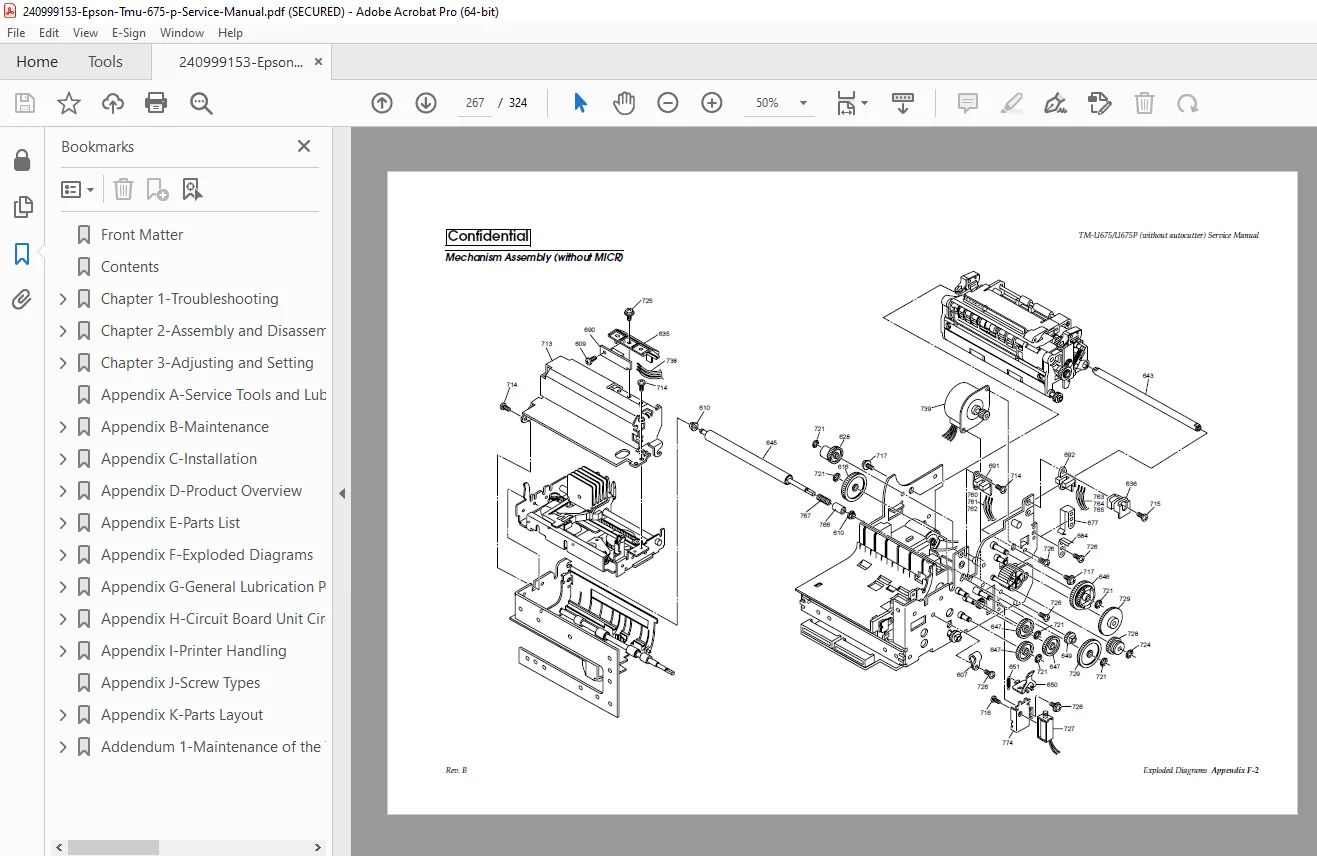
APPENDIX F: EXPLODED DIAGRAMS
- TM-U675/U675P – Complete printer exploded view
- Mechanism Assembly (without MICR)
- Mechanism Assembly (with MICR)
- Frame Assembly (without MICR)
- Frame Assembly (with MICR)
- Carriage Assembly – Detailed carriage components
- PF Assembly – Paper feed components
- MICR Unit – MICR assembly components
APPENDIX G: GENERAL LUBRICATION POINT DIAGRAMS
- Complete lubrication diagrams for all assemblies
- Lubrication points marked
- Lubricant type specifications
- Application methods
APPENDIX H: CIRCUIT BOARD UNIT CIRCUIT DIAGRAMS
- Main Circuit Board Assembly (Outline + 4 detailed sheets)
- Main Circuit Board (MICR I/F Block)
- Main Circuit Board (Memory Block)
- RS-232 I/F Circuit Board (UB-S01)
- Parallel I/F Circuit Board (UB-P02)
- RS-485 I/F Circuit Board (UB-S02)
- Complete schematics with component values
APPENDIX I: PRINTER HANDLING
- Using the Power Switch Cover
- Opening the Front Cover
- Installing or Replacing Paper Roll – Step-by-step procedures
- Removing Paper
- Installing Ribbon Cassette
- Inserting Slip Paper
- Inserting Validation Paper
- Reading MICR Characters on Personal Checks
- Adjusting Roll Paper Near End Detector
- Using the Control Panel – Complete control panel guide
- Button functions (FEED, RELEASE)
- LED indicators (PAPER OUT, SLIP)
APPENDIX J: SCREW TYPES
- Identification of all screw types
- Screw specifications
- Proper torque values
APPENDIX K: PARTS LAYOUT
- Main Circuit Board Unit (Parts Side)
- Main Circuit Board Unit (Solder Side)
- RS-232 I/F Circuit Board (UB-S01)
- Parallel I/F Circuit Board (UB-P02)
- RS-485 I/F Circuit Board (UB-S02)
- Component location diagrams
ADDENDUM 1: MAINTENANCE OF TM-U675 WITH PAPER PATH SPACERS
- TM-U675 PPSS Model Configuration
- TM-U675 PPSS Model Repair procedures
- How to Identify TM-U675 PPSS Model
- Installing and Removing Paper Path Spacer – Complete procedures
- Setting Threshold Values for Detectors – PPSS-specific adjustments
Key Features Requiring Service Attention
Three-Station Operation:
- Proper alignment of all three stations
- Paper path clearance
- Detector calibration
MICR Reader Service:
- Regular cleaning schedule
- MICR head sensitivity adjustment
- Character recognition testing
Print Quality Maintenance:
- Print head cleaning
- Platen gap adjustment
- Ribbon tension
Who Needs This Manual?
This Epson TM-U675 MICR printer troubleshooting manual is essential for:
- Authorized Epson service technicians
- POS equipment service companies
- Retail and banking equipment maintenance personnel
- Technical training centers
- Service centers specializing in POS equipment
- Anyone performing authorized repairs on TM-U675/U675P printers
Prerequisites:
✓ Authorized Epson service training
✓ Understanding of POS printer technology
✓ Electronic troubleshooting skills
✓ Mechanical repair aptitude
✓ Proper ESD handling procedures
✓ Access to required service tools
FILE DETAILS
| Detail | Specification |
|---|---|
| Manual Name | TM-U675/U675P (without autocutter) Service Manual |
| Models Covered | TM-U675, TM-U675P (without autocutter, with/without MICR, PPSS models) |
| Manual Code | 401093601 |
| Revision | Revision B |
| Language | English |
| Pages | 324 pages |
| PDF Quality | High-quality confidential service manual with detailed diagrams |
| File Size | 8.8 MB |
| Page Size | A4 (595 x 842 pts) |
| Copyright | Seiko Epson Corporation |
| Creator | FrameMaker 5.5P4fJ |
| Security | Print allowed, copy/modify restricted (confidential document) |
| PDF Version | 1.3 |