
FANUC ROBODRILL α-DiB5/α-DiB and α-DiB5ADV/α-DiBADV Robot Interface 2 Function Operator’s Manual B-85444EN-4/02
Original price was: $39.95.$24.95Current price is: $24.95.
Operator’s manual for the FANUC ROBODRILL Robot Interface 2 Function, covering FL-net connection, robot and ROBODRILL screens, interface signals, system control, robot programs, alarms, auto-door integration, and setup for α-DiB5, α-DiB, α-DiB5ADV, and α-DiBADV series machines.
Description
FANUC ROBODRILL Robot Interface 2 Function Operator’s Manual
This operator’s manual documents the Robot Interface 2 Function used to build a compact machining system that combines one or more FANUC ROBODRILL machines with a FANUC robot. It is written for the α-DiB5/α-DiB series and α-DiB5ADV/α-DiBADV series, including standard and high-performance ROBODRILL models. The document number printed on the manual is B-85444EN-4/02, and the revision record shows edition 02 dated December 2016.
The manual addresses the practical work of connecting, configuring, operating, and troubleshooting a ROBODRILL and robot cell. It covers the Robot Interface 2 screen structure, the signals exchanged between the robot controller and ROBODRILLs, FL-net communication, safety-fence and auto-door wiring, system start and stop control, robot programs, alarms, and optional setups such as a servo motor driven side door or simultaneous use of the data server function.
File Details
- Manual type: Operator’s Manual
- Brand: FANUC
- Model series: ROBODRILL α-DiB5/α-DiB and α-DiB5ADV/α-DiBADV
- Document number: B-85444EN-4/02
- Edition and date: Edition 02, December 2016
- Language: English
- Page count: 312 pages
- File format: PDF
Chapters Covered
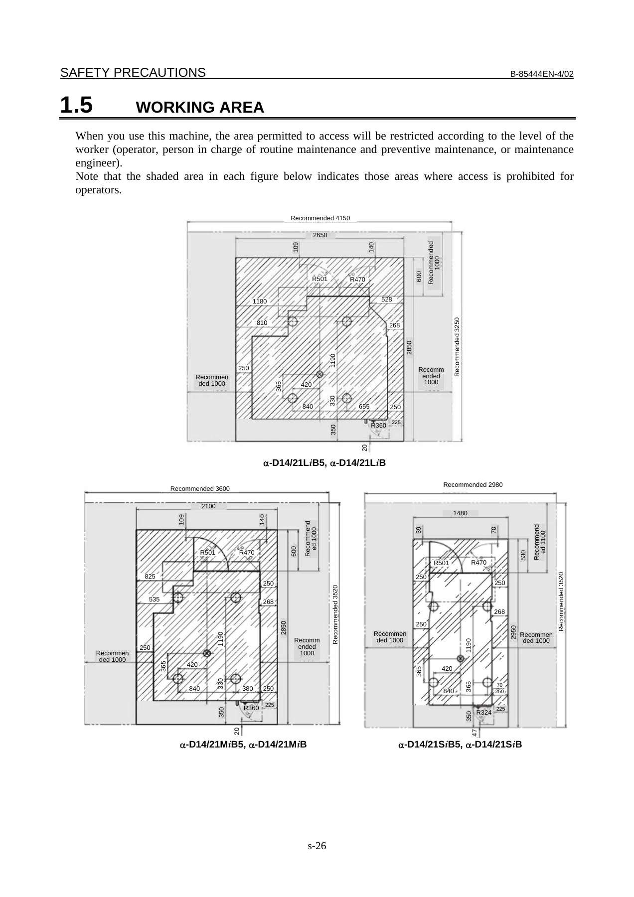
- Safety Precautions – safety functions of the machine, precautions for use, installation, maintenance, working area, noise, and warning labels
- Preface – intended use, definition of users, model names, related manuals, declaration of conformity, and contact information
- 1. Overview and Notes – overview, cautions, restrictions on operation, ROBODRILL and robot operating states and modes, and list of states and operation conditions
- 2. Connection – FL-net Ethernet connection, front auto-door driven by servo motor, side auto-door driven by air cylinder, and side auto-door driven by servo motor
- 3. Screen Configuration of Robot Interface 2 – quick screen, SYSTEM START/MONITOR screen, MANUAL OPERATE screen, PRODUCTION COUNTER screen, MAINTENANCE-1 PROG. screen, MAINTENANCE-2 SIGNAL screen, MAINTENANCE-3 SET. screen, and iHMI screens
- 4. Used Signals – interface signals between the ROBODRILL and robot, robot I/O assignment, flag signal table, DI to DO connection, GI/GO comments, DI/DO signal comments, and peripheral equipment control signals for the ROBODRILL custom PMC function
- 5. Setting of the ROBODRILL – CNC parameters, PMC parameters, FL-net settings, and Ethernet settings
- 6. System Control – timing charts, details of system control, M codes, system/stand-alone and system start, and system stop and cycle stop
- 7. Alarms and Messages – machine alarms EX alarms and operator messages
- 8. Functions of the Robot Controller – machine interlock operation, master ROBODRILL change and degradation operation, manual robot operation from the ROBODRILL, ROBODRILL status display on the robot teach pendant, tool length compensation display and change, ROBODRILL jog feed, bulk input of connection settings, I/O comment transfer, and robot controller alarm display
- 9. Setting of the Robot – loading settings by number of ROBODRILLs, background logic programs, reference positions, robot jog feed settings, jog coordinate systems, I/O comment transfer, tool offset screen, machine tool operation screen, advanced robot controller settings, system settings, FL-net, and FL-net-related settings
- 10. Robot Programs – background logic programs, macro programs, PNS programs, robot remote operation programs, home position return, hand operation macros, manual operation macros, and robot PNS programs for system operation
- 11. Robot Operations from ROBODRILLs – relationships between ROBODRILL statuses and robot operations
- 12. ROBODRILL Screen Operations from the Robot – CNC status display screen, actual position, alarm, message, running program, I/O screen, machine tool operation screen, and tool offset screen
- 13. In the Case of a Servo Motor Driven Side Door – overview, notes, ROBODRILL parameters, interface between ROBODRILL and robot, signal setting, system control time charts, system control details, M codes, alarms, and messages
- Appendix A. If Not Using the Robot Interface 2 Function – connection arrangements, PMC parameter settings, I/O signals, opening and closing the side door, peripheral control signals, alarms, and messages
- Appendix B. Ordering Information – Robot Interface 2 combinations, software options, electrical unit options, mechanical unit options, and FANUC robot controller software options
- Appendix C. Wiring Method – terminal block wiring, wire preparation, jumper removal and mounting
- Appendix D. Appearance Diagrams of ROBODRILLs with Side Auto-Doors Attached – right and left side auto-door arrangements for M, L, and S models
- Appendix E. Greasing Side Auto-Doors – greasing procedure for servo motor driven side auto-doors
- Appendix F. Setup – setup procedure and available signals with and without the Robot Interface 2 Function
- Appendix G. Mounting the Servo Motor – necessary parts and work procedure for a servo motor driven side auto-door
- Appendix H. If Using the Data Server Function Simultaneously – connection, parameters, and IP addresses
The manual goes beyond a simple screen reference. It defines the operating states that determine whether a ROBODRILL can run a program, when a side door may open, how a master ROBODRILL is selected, and how the robot and machine exchange service requests, cycle stop requests, system stop requests, door commands, jog commands, override changes, and production count pulses. It also documents the FL-net common memory layout and the safety signals used by the robot and ROBODRILLs. For a technician commissioning or maintaining a robot-linked ROBODRILL cell, the value is in having the signal ranges, parameter bits, timing charts, and program examples in one place, rather than trying to reconstruct the interface from separate controller and machine documents.
Commissioning and Safety Integration
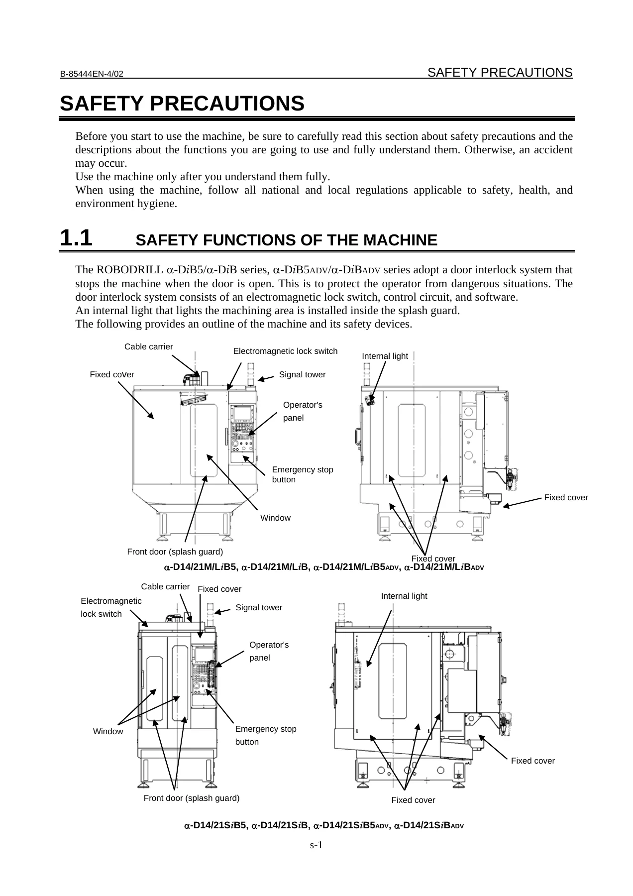
The opening safety section identifies the door interlock system, electromagnetic lock switch, fixed covers, emergency stop button, and the restrictions that apply when the front door or side door is open. The Robot Interface 2 chapters then put those safety principles into the cell configuration: the front and side doors are not normally permitted to open at the same time, the robot safety fence status is monitored, and the system treats certain door and fence combinations as a fence-open condition. The connection chapters show the FL-net Ethernet layout, hub connections, safety fence cable routing, relay terminal blocks, and circuit diagrams for front auto-door and side auto-door arrangements. Separate sections address air cylinder driven side doors and servo motor driven side doors, because the door control source and open-end signal handling differ.
Signals, Screens, and System Control
A large part of the manual is devoted to the signals that make the cell work. It lists signals sent from the robot controller to all ROBODRILLs, signals sent to each ROBODRILL individually, signals sent from each ROBODRILL back to the robot controller, and signals used internally by the robot controller. The tables include robot signal numbers, ROBODRILL PMC addresses, I/O comments, and signal counts. The screen chapter explains the QUICK screen and iHMI screen paths for system start and monitoring, manual robot operation, production counter management, program selection, signal monitoring, and system settings. The system control chapter provides timing charts for normal machining completion, cycle stop, and system stop, along with M code explanations for robot service requests, work-piece install requests, process completion notice, and side door open and close commands.
Robot Programs and Controller Settings
The manual includes background logic program descriptions, macro program tables, and PNS program examples for system operation. It shows how a master ROBODRILL is selected, how signals from multiple ROBODRILLs are handled by background logic, and how robot programs can respond to service requests and stop requests. The robot setting chapter describes loading settings according to the number of connected ROBODRILLs, running background logic programs, setting reference positions, configuring jog coordinate systems, transferring I/O comments to the ROBODRILL, and enabling robot jog feed or tool offset changes from the teach pendant. Advanced settings cover TCP/IP, FL-net, the safety function by FL-net, safe I/O connect, client tags, alarm message transfer, override step change, and MTCOM connection retry.
Maintenance, Alarms, and Optional Configurations
Alarm and message tables list machine alarms such as auto-door total time over, side door switch defective, and robot in service, together with operator messages such as safety gate open, teaching mode, side door and safety door open, and front or side door open restrictions. The appendices extend the manual to installations that do not use the Robot Interface 2 Function, ordering information for Robot Interface 2 combinations and options, terminal block wiring, appearance diagrams for side auto-door machines, greasing of side auto-doors, servo motor mounting, and simultaneous use of the data server function. This makes the document useful not only for initial setup but also for later maintenance, option checks, and troubleshooting when the robot and ROBODRILL do not behave as expected.
What This Manual Supports
IMAGES PREVIEW
With this FANUC ROBODRILL Robot Interface 2 Function Operator’s Manual, a maintenance engineer or system integrator can identify the correct FL-net connection points, confirm the signal addresses used between the robot and each ROBODRILL, set the ROBODRILL parameters that enable system mode and auto-door control, configure the robot controller for one to four ROBODRILLs, and understand how system start, cycle stop, and system stop are requested and acknowledged. It supports commissioning checks, signal troubleshooting, robot program review, screen operation from the ROBODRILL or robot teach pendant, and maintenance of the safety fence and auto-door circuits. Correct procedures and parameter settings matter in a robot cell because a wrong signal assignment or door condition can prevent system start, cause an unexpected stop, or leave the robot and machine out of synchronization. The manual provides the reference tables and examples needed to work through those conditions methodically. Delivery is by instant PDF download after payment, with no shipping, and the file can be viewed on a computer, tablet, or phone and printed for workshop use.
Reviews
There are no reviews yet.