★ TRUSTED BY 321,897+ PROFESSIONALS WORLDWIDE
🏢
Trusted Business
Verified & Licensed
🛡️
Virus Free Files
100% Safe Downloads
🔒
Secure Payment
SSL Protected
Instant Delivery
Available Immediately
Sale!

Fendt 1000 Vario S4 Workshop Service Manual 1038 1042 1046 1050 May 2018

Original price was: $42.95.Current price is: $25.95.

May 2018 workshop service manual for the Fendt 1000 Vario S4 series covering the 1038, 1042, 1046 and 1050. Safety, specifications, calibrations, fault codes, and system repair procedures for engine, Vario transmission, hydraulics, electrics, axles and lifts.

Instant PDF Download
Available immediately
💾
Save to Your Device
Download & keep forever
🛡️
Antivirus Scanned
100% virus-free
🌍
Trusted Worldwide
175,000+ customers

Description

Fendt 1000 Vario S4 Workshop Service Manual 1038 1042 1046 1050 May 2018

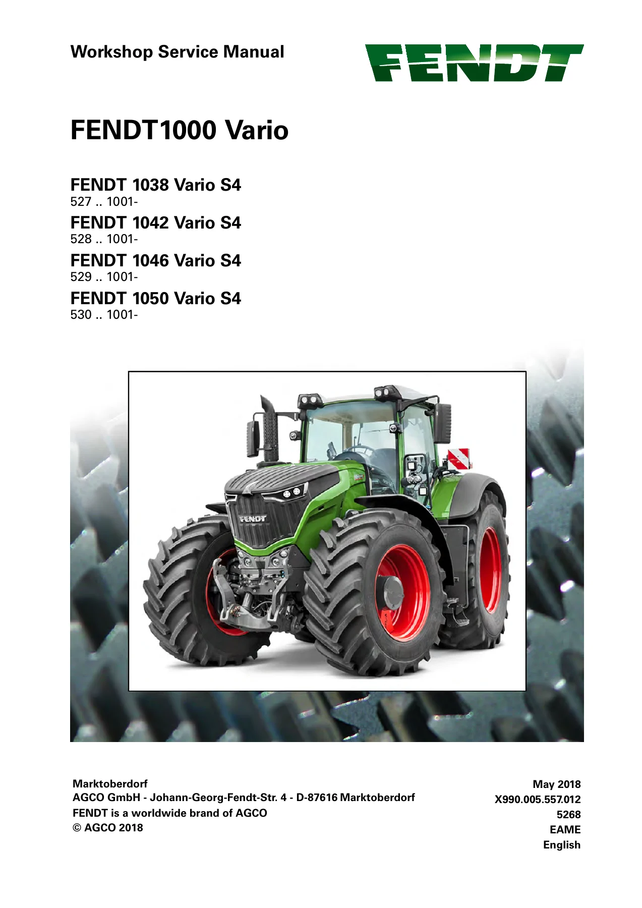
This Fendt 1000 Vario S4 Workshop Service Manual 1038 1042 1046 1050 May 2018 is the workshop service volume issued for the FENDT 1000 Vario S4 tractor family. The cover identifies FENDT 1038 Vario S4 (527 .. 1001-), FENDT 1042 Vario S4 (528 .. 1001-), FENDT 1046 Vario S4 (529 .. 1001-) and FENDT 1050 Vario S4 (530 .. 1001-). Publication data on the title leaf is Marktoberdorf, AGCO GmbH, May 2018, document number X990.005.557.012, English, EAME. The text is written for trained workshop personnel who already know the operator’s manual and need assembly, measurement, calibration and diagnosis detail that goes far beyond routine daily service.

File Details

  • Manual type: Workshop Service Manual
  • Brand / series: FENDT 1000 Vario S4
  • Models: FENDT 1038 Vario S4, FENDT 1042 Vario S4, FENDT 1046 Vario S4, FENDT 1050 Vario S4
  • Language: English
  • Page count: 1805
  • File format: PDF
  • Document number: X990.005.557.012
  • Date: May 2018
  • Publisher location: AGCO GmbH, Johann-Georg-Fendt-Str. 4, D-87616 Marktoberdorf

Which tractors this volume matches

The assignment table in the entire-vehicle chapter maps the FENDT 1000 Vario series to EU type approval e1*167/2013*00055 and chassis type codes T527, T528, T529 and T530. Technical specification tables further tag the four tractor types with VIN prefixes WAM531…. (1038), WAM532…. (1042), WAM533…. (1046) and WAM534…. (1050). The opening note states that the document is valid from the chassis numbers printed on the cover and that the last valid chassis number had not been fixed at the time of writing; AGCONET or FENDT Technical Service is named as the place to check whether a later wiring-diagram set exists.

Equipment tables distinguish PowerPlus, PROFI and ProfiPlus specification packages. Those lists cover Vario operation (joystick versus multifunction joystick, 7 in or 10.4 in Varioterminal, Variotronic implement control, Vario TMS, VarioDoc / VarioDoc Pro, VarioGuide, VarioActive), cab suspension options, reverse-drive function, engine and transmission extras, pneumatic brake layouts, Fendt Stability Control and VarioGrip tire-pressure monitoring. Use the tables when confirming whether a procedure applies to the tractor on the stand.

Engine, chassis and system figures used throughout the book

All four models share the MAN D2676 LE121 six-cylinder, 4-stroke, water-cooled in-line diesel with direct injection, MAN Common Rail and EDC 17 electronic control. Displacement is 12419 cm3 with 126 mm bore and 166 mm stroke, compression ratio 17:1, firing order 1-5-3-6-2-4. Rated speed is 1700 rpm and idle speed is 600 rpm. Rated power to ECE R24 at 1700 rpm is given as 291 kW / 396 HP on the 1038, 320 kW / 435 HP on the 1042, 350 kW / 476 HP on the 1046 and 380 kW / 517 HP on the 1050. Maximum torque to ECE R24 is 1900 Nm, 2100 Nm, 2300 Nm and 2400 Nm respectively. The fuel tank is listed at 800 l; approximate full-load fuel consumption is 76, 84, 92 and 100 l/h. Exhaust after-treatment is described as Tier 4f with SCR catalytic converter, external exhaust-gas recirculation, VTG turbocharger with exhaust-brake function and an 84 l AdBlue tank.

Complete PDF Bookmark Tree

Complete Bookmarks

The complete bookmarks in the “Fendt 1000 Vario S4 Workshop Service Manual 1038 1042 1046 1050 May 2018” are as follows:

FENDT1000 Variop. 1
TABLE OF CONTENTp. 3
1. 00-000 Entire vehicle systemp. 4
1.1 Safety instructionsp. 8
1.1.1 Safety briefing and measuresp. 8
1.1.2 Importance of and position of the safety decalsp. 10
1.2 General informationp. 21
1.2.1 Assignment table FENDT T types to the EU Type Approval Numberp. 21
1.2.2 Meaning of the vehicle identification numberp. 22
1.2.3 Notes on documentationp. 22
1.2.4 Note on hydraulicsp. 23
1.2.5 Support points for jack and support standsp. 24
1.2.6 Location of the identification platesp. 26
1.2.7 Standard and additional equipmentp. 28
1.2.8 Identification of electrical cablesp. 34
1.3 Tightening requirementsp. 38
1.3.1 Spanner sizes for globally standard partsp. 38
1.3.2 Tightening torque for screws with a galvanized surfacep. 38
1.3.3 Tightening torque for screws and bolts with VDA coatingp. 40
1.3.4 Tightening requirements for threaded plugsp. 40
1.3.5 Tightening requirements of banjo boltsp. 41
1.3.6 Tightening torques for hose clampsp. 42
1.4 Fuels and lubricantsp. 44
1.4.1 Biodieselp. 44
1.4.2 Biodegradable hydraulic oilp. 44
1.5 Technical specificationp. 46
1.5.1 Generalp. 47
1.5.2 Diesel enginep. 51
1.5.3 Front axlep. 57
1.5.4 Steeringp. 59
1.5.5 Gearboxp. 60
1.5.6 Compressed air systemp. 66
1.5.7 Hydraulic equipmentp. 68
1.5.8 Electrical systemp. 71
1.5.9 Cabp. 72
1.5.10 Air-conditioning systemp. 73
1.5.11 Front power liftp. 74
1.5.12 Rear power liftp. 75
1.6 Component positionp. 76
1.6.1 Electrical/electronic components – Ap. 76
1.6.2 Electrical/electronic components – Bp. 84
1.6.3 Electrical/electronic components – Ep. 98
1.6.4 Electrical/electronic components – Fp. 115
1.6.5 Electrical/electronic components – Gp. 115
1.6.6 Electrical/electronic components – Hp. 116
1.6.7 Electrical/electronic components – Kp. 117
1.6.8 Electrical/electronic components – Mp. 120
1.6.9 Electrical/electronic components – Np. 125
1.6.10 Electrical/electronic components – Rp. 126
1.6.11 Electrical/electronic components – Sp. 127
1.6.12 Electrical/electronic components – Up. 135
1.6.13 Electrical/electronic components – Xp. 135
1.6.14 Electrical/electronic components – Yp. 200
1.6.15 Position of socketsp. 211
1.6.16 Transmission componentsp. 217
1.6.17 Hydraulic componentsp. 229
1.6.18 Compressed air system componentsp. 255
1.6.19 Components of the tire pressure monitoring systemp. 266
1.7 Position of measuring pointsp. 278
1.7.1 Measuring points on transmission and comfort hydraulicsp. 278
1.7.2 Hydraulic measuring pointsp. 282
1.7.3 Measuring points compressed air systemp. 284
1.8 Settings and calibrationp. 287
1.8.1 General information on calibrationp. 287
1.8.2 Calibration code 1001 – crossgate leverp. 291
1.8.3 Calibration code 1003 … 1006 – Linear modulep. 296
1.8.4 Calibration code 2401 – steering angle sensorp. 299
1.8.5 Calibration code 2403 – Steering valve VarioGuidep. 306
1.8.6 Calibration of transmissionp. 309
1.8.6.1 Calibration code 4001 – clutch pedalp. 309
1.8.6.2 Calibration code 4002 – hand throttlep. 311
1.8.6.3 Calibration code 4005 – accelerator / driving pedalp. 313
1.8.6.4 Calibration code 4007 – transmission ratio characteristicp. 315
1.8.6.5 Calibration code 4009 – turbo-clutch functionp. 321
1.8.6.6 Calibration code 4010 – Driving pedal resolutionp. 325
1.8.7 Calibration code 6034 – rear PTO clutchp. 327
1.8.8 Calibration code 7666 – front axle suspensionp. 329
1.8.9 Calibration code 8001 / 8002 – Rear EPCp. 331
1.8.10 Calibration code 9001 / 9002 front EPCp. 337
1.8.11 Calibrating the heater valve (no code)p. 342
1.8.12 Calibrating speed displayp. 343
1.8.13 Maintenance — change windscreen wiper (300°) (no code)p. 345
1.8.14 Calibration of the gyro compassp. 347
1.9 Calibrations fault codep. 348
1.9.1 Calibration fault code 1001p. 348
1.9.2 Calibration fault code 1003p. 348
1.9.3 Calibration fault code 1004p. 348
1.9.4 Calibration fault code 1005p. 349
1.9.5 Calibration fault code 1006p. 349
1.9.6 Calibration fault code 2401p. 349
1.9.7 Calibration fault code 2403p. 350
1.9.8 Calibration fault code 4001p. 350
1.9.9 Calibration fault code 4002p. 351
1.9.10 Calibration fault code 4005p. 351
1.9.11 Calibration fault code 4007p. 351
1.9.12 Calibration fault code 4009p. 353
1.9.13 Calibration fault code 4010p. 354
1.9.14 Calibration fault code 7666p. 354
1.9.15 Calibration fault code 8001p. 355
1.9.16 Calibration fault code 9001p. 355
1.9.17 Calibration fault code tyre circumferencep. 355
1.9.18 Heater valve calibration fault codep. 356
1.10 Fault code tablesp. 357
1.10.1 Note on the fault code tablep. 357
1.10.2 Confirm, call up and delete fault codep. 357
1.10.3 Fault code 00.0.00p. 359
1.10.4 Fault code 01.0.00p. 362
1.10.5 Fault code 02.1.00p. 368
1.10.6 Fault code 03.1.00p. 370
1.10.7 Fault code 04.1.00p. 372
1.10.8 Fault code 05.1.00p. 387
1.10.9 Fault code 06.1.00p. 393
1.10.10 Fault code 08.1.00p. 398
1.10.11 Fault code 09.1.00p. 404
1.10.12 Fault code 0A.1.00p. 409
1.10.13 Fault code 0B.1.00p. 429
1.10.14 Fault code 0D.1.00p. 432
1.10.15 Fault code 0E.1.00p. 434
1.10.16 Fault code 0F.1.00p. 439
1.10.17 Fault code 10.1.00p. 444
1.10.18 Fault code 12.1.00p. 446
1.10.19 Fault code 15.1.00p. 454
1.10.20 Fault code 17.1.00p. 456
1.10.21 Fault code 18.1.00p. 457
1.10.22 Fault code 1A.1.00p. 461
1.10.23 Fault code 1D.1.00p. 467
1.10.24 Fault code 1F.1.00p. 479
1.10.25 Fault code 20.1.00p. 480
2. 01-000 Engine, fuel and exhaust systemp. 486
2.1 Generalp. 488
2.1.1 Assignment of FENDT – MAN component designationsp. 488
2.1.2 Engine horsepower: comparison of standards and directivesp. 488
2.1.3 General description of the common rail systemp. 490
2.1.4 Combustion air ratiop. 491
2.1.5 Immobilizerp. 492
2.2 Enginep. 494
2.2.1 PTO power and fuel consumptionp. 494
2.2.1.1 Measurement of the PTO power in accordance with ISO1585p. 494
2.2.1.2 Measurement of the PTO power and fuel consumptionp. 496
2.2.1.3 Diagrams for the PTO power and fuel consumptionp. 497
2.2.2 Belt layoutp. 501
2.2.3 Engine controlp. 501
2.2.4 Camshaftp. 503
2.2.4.1 Description of camshaft sensorp. 504
2.2.5 Crankshaftp. 505
2.2.5.1 Description of crankshaft sensorp. 506
2.2.6 Front and rear gear casingp. 507
2.3 Intake systemp. 509
2.3.1 Torque values of the intake systemp. 509
2.3.2 B092 – Charge air pressure/temperature sensorp. 510
2.3.3 Turbochargerp. 510
2.3.4 B270 – Lambda probep. 512
2.4 Fuel systemp. 514
2.4.1 Fuel system diagramp. 514
2.4.2 Fuel tankp. 515
2.4.3 Thermostatic valvep. 516
2.4.3.1 Thermostatic valve switching pointsp. 516
2.4.3.2 Thermostatic valve in the filter headp. 517
2.4.3.3 Install the thermostatic valvep. 519
2.4.3.4 Remove the thermostatic valvep. 521
2.4.4 Fuel pre-filterp. 523
2.4.4.1 Drain water from the fuel pre-filterp. 524
2.4.4.2 Check the non-return valvep. 525
2.4.4.3 Bleed air from the fuel systemp. 525
2.4.5 Fuel filterp. 526
2.4.6 Fuel pumpp. 528
2.4.7 High-pressure pumpp. 529
2.4.8 Rail pressure relief valvep. 532
2.4.8.1 Remove the rail pressure relief valvep. 533
2.4.8.2 Install rail pressure relief valvep. 534
2.4.9 Rail pressure sensorp. 535
2.4.9.1 Remove B086 – Rail pressure sensorp. 535
2.4.9.2 Install B086 – Rail pressure sensorp. 536
2.4.10 Injectorsp. 537
2.4.10.1 Check injectorp. 538
2.4.11 Metering unitp. 540
2.5 Cooling systemp. 542
2.5.1 Engine blockp. 543
2.5.2 Coolant distributor housingp. 546
2.5.3 Attach cooling water system components on the engine blockp. 548
2.5.4 Fuel coolerp. 550
2.6 Lubrication oil systemp. 551
2.6.1 Oil sumpp. 553
2.6.2 Lubrication pumpp. 554
2.6.3 Oil module with crankcase breatherp. 556
2.7 Exhaust gas systemp. 559
2.7.1 Generalp. 559
2.7.1.1 Combustion gases from a diesel enginep. 559
2.7.1.2 Boostingp. 560
2.7.1.3 Exhaust gas recirculationp. 561
2.7.1.4 Particulate filter and oxidation catalytic converterp. 562
2.7.1.5 General description of the SCR reactionp. 564
2.7.2 Exhaust gas after-treatment and charge air system – Schematicp. 568
2.7.2.1 A151 – Nitrogen oxide sensor 2, downstream of SCR catalytic converterp. 569
2.7.2.2 A153 – Exhaust gas temperature sensor, upstream/downstream of SCR catalytic converterp. 570
2.7.2.3 A170 – Nitrogen oxide sensor 1, upstream of SCR catalytic converterp. 570
2.7.3 Cooled exhaust gas recirculationp. 571
2.7.4 SCR systemp. 575
2.7.4.1 Removal of SCR catalytic converterp. 577
2.7.4.2 Install SCR catalytic converterp. 580
2.7.4.3 AdBlue®-Containerp. 583
2.7.4.4 A155 – AdBlue® supply modulep. 583
2.7.4.5 A156 – AdBlue® metering valvep. 586
2.7.4.6 B195 – AdBlue® level/temperature/quality sensorp. 588
3. 02-000 Front axlep. 590
3.1 Generalp. 592
3.1.1 Remove the front axlep. 592
3.1.2 Install front axlep. 610
3.1.3 Hydraulic diagram of transmission lubricationp. 624
3.1.4 Front axle lubrication pressurep. 624
3.1.5 Refit components when replacing the front axlep. 626
3.2 Front axle suspensionp. 631
3.2.1 Electric functional plan for front axle suspensionp. 631
4. 03-000 Steering systemp. 632
4.1 Steering unitp. 634
4.1.1 Electrohydraulic steering system OSPEC LSMRp. 634
4.1.2 Steering hydraulicsp. 636
4.1.3 Remove steering servo unit – without reverse drive controlp. 639
4.1.4 Install steering servo unit – without reverse drive controlp. 647
4.1.5 Remove steering servo unit – with reverse drive controlp. 657
4.1.6 Install steering servo unit – with reverse drive controlp. 660
4.2 Way line guidancep. 664
4.2.1 Components of way line guidancep. 664
4.2.2 A101 – VarioDoc/VarioGuide ECU EU version with GPRS modemp. 670
4.2.3 A101 – VarioDoc/VarioGuide ECU: NA version with CDMA mobile radio modemp. 671
5. 04-000 Drive trainp. 672
5.1 Generalp. 674
5.1.1 Functional descriptionp. 674
5.1.1.1 Transmission datap. 674
5.1.1.2 Transmission hydraulics circuit diagramp. 676
5.1.1.3 Electric functional plan for transmissionp. 678
5.1.1.4 Transmission controlp. 682
5.1.1.5 Transmission function diagramp. 684
5.1.1.6 Transmission functionsp. 696
5.1.1.7 Load limit controlp. 697
5.1.2 Componentsp. 699
5.1.2.1 Tasks of electrical componentsp. 699
5.1.2.2 Position of hydraulic linesp. 700
5.1.3 Valve blocksp. 702
5.1.3.1 Feed/lubrication valve blockp. 702
5.1.4 Repair instructionsp. 703
5.1.4.1 Fill the high-pressure circuitp. 703
5.1.4.2 Towing selectorp. 704
5.1.4.3 B008 – High pressure sensor 1p. 710
5.1.4.4 B009 – Discharge temperature sensorp. 710
5.1.4.5 B015 – Bevel pinion speed sensorp. 711
5.1.4.6 B039 – High pressure sensor 2p. 713
5.1.4.7 B225 – Hydraulic motor 2 speed sensorp. 713
5.1.4.8 B230 – Collecting shaft sensorp. 714
5.1.5 Pressure measurementp. 715
5.1.5.1 General information on complaints relating to powerp. 715
5.1.5.2 Transmission high-pressure test at terminalp. 716
5.1.5.3 Preparation of the transmission for high-pressure testp. 719
5.1.5.4 Pressure measurement test reportp. 722
5.1.5.5 Check clutch/turboclutchp. 730
5.1.6 Transmission controlp. 736
5.1.6.1 Installation of the A009 – Actuator unitp. 742
5.1.6.2 Set the transmission to neutralp. 745
5.1.6.3 Actuator shaftp. 747
5.2 Rear axlep. 750
5.2.1 Final drive axlep. 750
5.2.1.1 Dismantle the rear axlep. 753
5.2.2 Differential unitp. 758
5.2.2.1 Differential lock electric functional planp. 758
5.2.2.2 Remove differentialp. 758
5.2.2.3 Dismantling differentialp. 761
5.2.2.4 Assemble the differentialp. 767
5.2.2.5 Install differential and set backlashp. 775
5.2.2.6 Dismantling the pinion shaftp. 781
5.2.2.7 Adjusting and fitting the pinion shaftp. 785
5.2.2.8 Y010 – Differential lock solenoid valvep. 790
5.3 Vario insertp. 792
5.3.1 Removal of the transmissionp. 792
5.3.2 Installation of the transmission unitp. 802
5.3.3 Flushing valve 2V5p. 827
5.3.3.1 Replace the flushing valve 2V5p. 829
5.3.4 High-pressure relief valve 2V3 / 2V4p. 830
5.3.4.1 Replace the high-pressure limiting valve 2V3 / 2V4p. 831
5.4 Couplingp. 833
5.4.1 Y004 – Clutch/turbo-clutch solenoid valvep. 839
5.5 Rear PTOp. 841
5.5.1 Electric functional plan for rear PTOp. 841
5.5.2 Ranges and stub shaftsp. 841
5.5.3 Rear PTO speed monitoringp. 843
5.5.4 Technical drawingp. 844
5.5.5 Remove rear axle coverp. 847
5.5.6 Dismantle the rear PTO clutchp. 854
5.5.7 Remove rear PTO transmissionp. 859
5.5.8 Install rear PTO transmissionp. 865
5.5.9 Install rear PTO clutchp. 874
5.5.10 Install the rear-axle coverp. 884
5.5.11 B020 – Rear PTO stub shaft speed sensorp. 893
5.5.12 Y008 – Rear PTO clutch solenoid valvep. 893
5.5.13 Y026/Y027 – Rear PTO range I/II selection solenoid valvep. 894
5.6 Front wheel drivep. 896
5.6.1 Electric functional plan four-wheel drivep. 896
5.6.2 B229 – 4WD clutch sensorp. 897
5.6.3 Y213 – 4WD clutch solenoid regulator valvep. 899
5.6.4 Y214 – 4WD clutch solenoid switching valvep. 900
5.7 Brake systemp. 903
5.7.1 Rear wheel brakep. 903
5.7.1.1 Rear wheel brake removalp. 907
5.7.1.2 Rear wheel brake installationp. 920
5.7.2 Brake adjustmentp. 938
5.7.3 S105 / S106 – Brake switchp. 942
5.7.4 Parking brakep. 943
5.7.4.1 Status/warning light activationp. 943
5.7.5 Hand brakep. 944
5.7.5.1 Functional description of hand brake leverp. 944
5.8 Housingp. 945
5.8.1 Separate tractor between transmission and rear axlep. 945
5.8.2 Disconnect the tractor between the clutch housing and transmission housingp. 955
5.8.3 Connect the tractorp. 975
5.8.4 Remove clutch housingp. 996
5.8.5 Fit clutch housingp. 1022
6. 05-000 Compressed-air systemp. 1042
6.1 Generalp. 1044
6.1.1 Compressed air pipes acc. to DIN 74324p. 1044
6.1.2 Unlocking tool for compressed air pipesp. 1044
6.1.3 Tightening torques for compressed air connection systemp. 1044
6.2 Tire pressure monitoring systemp. 1047
6.2.1 Function and fault outputp. 1047
6.2.2 Settings on the terminalp. 1048
6.2.3 Functional plansp. 1051
6.2.4 Test toolp. 1060
7. 06-000 Hydraulic systemp. 1064
7.1 Generalp. 1066
7.1.1 Commissioning of the variable displacement pumpp. 1066
7.1.2 Electric functional plan: Hydraulics protection and supplyp. 1067
7.1.3 Y060 – (Rear) hydraulic oil preheater solenoid valvep. 1068
7.2 Pressure testingp. 1069
7.2.1 Test report for pressure test for one variable displacement pumpp. 1069
7.2.2 Test report for pressure test on two variable displacement pumpsp. 1074
7.3 Hydraulic pump service hatchp. 1084
7.3.1 Open the hydraulic pump service hatchp. 1084
7.3.2 Close the hydraulic pump service hatchp. 1089
7.4 Fan pumpp. 1094
7.4.1 Fan hydraulicsp. 1094
7.4.2 Remove fan pump when tractor is separatedp. 1095
7.4.3 Install fan pump when tractor is separatedp. 1097
7.4.4 Remove the fan pump via the service hatchp. 1099
7.4.5 Install the fan pump via the service hatchp. 1106
7.4.6 Commissioning of fan after component replacementp. 1115
7.5 Variable displacement pump 2p. 1116
7.5.1 Remove variable displacement pump 2 when tractor is separatedp. 1116
7.5.2 Install variable displacement pump 2 when tractor is separatedp. 1118
7.5.3 Remove variable displacement pump 2 through the service hatchp. 1120
7.5.4 Install variable displacement pump 2 through the service hatchp. 1124
7.5.5 Y219 – Charge control pump 2 solenoid valvep. 1129
7.6 Steering and lubrication pumpp. 1130
7.6.1 Remove the steering pump and lubrication pumpp. 1130
7.6.2 Modification of the steering and lubrication pump:p. 1132
7.6.3 Fit the steering and lubrication pumpp. 1135
7.6.4 S167 – Steering pump flow monitor switchp. 1139
7.7 Wheel-driven emergency steering pumpp. 1141
7.7.1 Removal of wheel-driven emergency steering pumpp. 1141
7.7.2 Installation of wheel-driven emergency steering pumpp. 1142
7.7.3 S173 – Wheel-driven emergency steering pump flow monitor switchp. 1144
7.8 Valvesp. 1146
7.8.1 Valve plates in the rearp. 1146
7.8.2 Central control blockp. 1147
7.8.3 Layout of the auxiliary spool valvesp. 1153
7.9 Emergency actuationp. 1155
7.9.1 Manual operation of the EHS valves in emergency modep. 1155
7.10 Maintenancep. 1158
7.10.1 Repair shuttle valvep. 1158
8. 07-000 Electrical systemp. 1160
8.1 Generalp. 1166
8.1.1 Component identification in accordance with DIN 40719p. 1166
8.1.2 Hall sensor operationp. 1166
8.1.3 Button & switch functionalityp. 1172
8.1.4 Rotary position sensor function, when used as a current dividerp. 1176
8.1.5 Pressure sensor function, when used as a current dividerp. 1181
8.2 Fuse assignmentp. 1186
8.2.1 Fuse assignmentp. 1186
8.3 CAN BUSp. 1194
8.3.1 Electrical/electronic components — CAN busp. 1194
8.3.2 Procedure in case of CAN bus errorsp. 1194
8.3.3 Transmission bus (G-Bus)p. 1196
8.3.4 ISOBUSp. 1198
8.3.5 Comfort-Bus (K-Bus)p. 1200
8.3.6 Engine bus (M-Bus)p. 1202
8.3.7 Valve bus (V-Bus)p. 1204
8.4 Measure and test – A componentsp. 1206
8.4.1 Electrical/electronic components – Ap. 1206
8.4.2 A007 – Instrument panelp. 1206
8.4.3 A009 – Actuator unitp. 1215
8.4.4 A011 – Radar sensorp. 1221
8.4.5 A036 – Control panel, right/left instrument panelp. 1222
8.4.6 Check A050 – Basic control unit ECU (EXT) with adapter boxp. 1226
8.4.7 A050 – Basic control unit ECU (EXT)p. 1229
8.4.8 A077 – Immobilizer ECUp. 1238
8.4.9 A087 – Tire pressure monitoring system (VarioGrip)p. 1240
8.4.10 Check A100 – Multifunction armrest (MFA) with adapter boxp. 1242
8.4.11 A100 – Multifunction armrest (MFA)p. 1245
8.4.12 A101 – VarioDoc/VarioGuide ECUp. 1249
8.4.13 A102 – Topcon receiver ECUp. 1251
8.4.14 A145 / A146 – fan regulator (left/right)p. 1253
8.4.15 Check A147 – Central electrical system (ZE) ECU with adapter boxp. 1257
8.4.16 A147 – Central electrical system (ZE) ECU: Power supplyp. 1260
8.4.17 A147 – Central electrical system (ZE) ECU: K-Bus, V-Bus, ISO-Busp. 1262
8.4.18 A147 – Central electrical system (ZE) ECU: Headlight, side light, direction indicatorp. 1264
8.4.19 A147 – Central electrical system (ZE) ECU: Warning horn, rotary beacon, wide vehicle markerp. 1270
8.4.20 A147 – Central electrical system (ZE) ECU: Work lightp. 1272
8.4.21 A147 – Central electrical system (ZE) ECU: Mirror and windscreen heating, windscreen wipersp. 1277
8.4.22 A147 – Central electrical system (ZE) ECU: Interior lightingp. 1281
8.4.23 A147 – Central electrical system (ZE) ECU: Automatic air-conditioning systemp. 1284
8.4.24 A147 – Central electrical system (ZE) ECU: Socketsp. 1290
8.4.25 A147 – Central electrical system (ZE) ECU: Starterp. 1295
8.4.26 A147 – Central electrical system (ZE) ECU: Reverse drive controlp. 1297
8.4.27 A150 – Relay fuse boardp. 1302
8.4.28 A151 – Nitrogen oxide sensor 2, downstream of SCR catalytic converterp. 1314
8.4.29 A153 – Exhaust gas temperature sensor, upstream/downstream of SCR catalytic converterp. 1316
8.4.30 A155 – AdBlue® supply modulep. 1317
8.4.31 A156 – AdBlue® metering valvep. 1318
8.4.32 A167 – Primary fan regulatorp. 1319
8.4.33 Check A169 – Engine control unit ECU (EDC 17) with adapter boxp. 1322
8.4.34 A169 – Engine control unit ECU (EDC 17)p. 1325
8.4.35 A170 – Nitrogen oxide sensor 1, upstream of SCR catalytic converterp. 1331
8.4.36 A173 – Trimble AG-382p. 1333
8.4.37 A174 – Satel EASyProofp. 1335
8.4.38 A177 – AGCO Connectivity Module (ACM)p. 1336
8.5 Measure and test – B componentsp. 1338
8.5.1 Electrical/electronic components – Bp. 1338
8.5.2 B007 – Immersed tube fuel sensorp. 1338
8.5.3 B008 – High pressure sensor 1p. 1340
8.5.4 B009 – Discharge temperature sensorp. 1342
8.5.5 B013 – Hydraulic oil temperature sensorp. 1344
8.5.6 B015 – Bevel pinion speed sensorp. 1347
8.5.6.1 B015 – Bevel pinion speed sensor: Functional descriptionp. 1349
8.5.7 B017 – Clutch pedal sensorp. 1350
8.5.8 B020 – Rear PTO stub shaft speed sensorp. 1352
8.5.9 B021 – Rear PTO pressure clutch speed sensorp. 1354
8.5.10 B039 – High pressure sensor 2p. 1356
8.5.11 B040 – Front power lift position sensorp. 1359
8.5.12 B055 – Foot throttle sensorp. 1361
8.5.13 B066 – Left wheel position (suspension) sensorp. 1364
8.5.14 B067 – Steering angle sensorp. 1366
8.5.15 B068 – Right wheel position (suspension) sensorp. 1368
8.5.16 B071 – Output temperature sensor (HVAC)p. 1370
8.5.17 B076 – Exterior temperature sensorp. 1372
8.5.18 B078 – Hand brake sensorp. 1374
8.5.19 B081 – Steering wheel sensor (360°)p. 1376
8.5.20 B084 – Hydraulic oil level sensorp. 1378
8.5.21 B086 – Rail pressure sensorp. 1381
8.5.22 B087 – Fuel low pressure sensorp. 1382
8.5.23 B090 – Engine oil pressure sensorp. 1387
8.5.24 B091 – Water in fuel sensorp. 1393
8.5.25 B092 – Charge air pressure/temperature sensorp. 1394
8.5.26 B145 – Rear power lift position sensorp. 1395
8.5.27 B158 – Solar sensor (radiated heat HVAC)p. 1397
8.5.28 B167 – Internal temperature sensorp. 1398
8.5.29 B187 – Evaporator temperature sensor (HVAC)p. 1400
8.5.30 B195 – AdBlue® level/temperature/quality sensorp. 1401
8.5.31 B204 – Coolant temperature sensorp. 1402
8.5.32 B215 – Air filter restriction sensorp. 1403
8.5.33 B217 – Temperature downstream of venturi sensorp. 1404
8.5.34 B221 – Rear power lift load detection sensorp. 1405
8.5.35 B225 – Hydraulic motor 2 speed sensorp. 1407
8.5.35.1 B225 – Hydraulic motor 2 speed sensor: Functional descriptionp. 1409
8.5.36 B226 – Air mass sensorp. 1411
8.5.37 B229 – 4WD clutch sensorp. 1412
8.5.38 B230 – Collecting shaft sensorp. 1415
8.5.38.1 B230 – Collecting shaft sensor: Functional descriptionp. 1417
8.5.38.2 B230 – Collecting shaft sensorp. 1418
8.5.39 B233 – Coolant level sensorp. 1420
8.5.40 B234 – Fan speed sensorp. 1421
8.5.41 B235 – Diesel engine external temperature sensorp. 1422
8.5.42 B246 – Hand brake lever pressure sensor, position 1+2p. 1423
8.5.43 B249 – Camshaft speed sensorp. 1425
8.5.44 B250 – Crankshaft speed sensorp. 1427
8.5.45 B270 – Lambda probep. 1429
8.5.46 B276 – Intake manifold temperature sensorp. 1430
8.5.47 B277 – Exhaust gas turbocharger (VTG) speed sensorp. 1431
8.5.48 B282 – Front axle oil pressure monitoringp. 1432
8.5.49 B283 – Compressed air supply sensor, circuit 2p. 1433
8.5.50 B284 – Compressed air supply sensor, circuit 1p. 1436
8.5.51 B290 – Brake pedal lock sensorp. 1438
8.6 Measure and test – E componentsp. 1440
8.6.1 Electrical/electronic components – Ep. 1440
8.6.2 E023 to E315 – Heatingp. 1440
8.6.3 E050 to E319 – Work Lightsp. 1441
8.6.4 E054 to E323 – Outdoor Lightingp. 1442
8.6.5 E158, E172, E173 – Interior Lightingp. 1444
8.6.6 E267 / E268 / E269 – AdBlue heaterp. 1445
8.7 Measure and test – G componentsp. 1446
8.7.1 Electrical/electronic components – Gp. 1446
8.7.2 G001 – Battery 1 and G003 – Battery 2p. 1446
8.7.3 G002 – Alternator 1p. 1450
8.7.3.1 G002 – Alternator 1: Potential faultsp. 1451
8.7.3.2 G002 – Alternator 1: Belt drive MAN D2676p. 1452
8.8 Measure and test – H componentsp. 1454
8.8.1 Electrical/electronic components – Hp. 1454
8.8.2 H005 – Warning hornp. 1454
8.8.3 H006 – Audible warning signalp. 1455
8.8.4 H009 – Reversing signal bleeperp. 1457
8.9 Measure and test – K componentsp. 1459
8.9.1 Electrical/electronic components – Kp. 1459
8.9.2 K17 / K18 – AdBlue heaterp. 1459
8.9.3 K115 / K116 – 12V / 24V starter relayp. 1460
8.10 Measure and test – M componentsp. 1461
8.10.1 Electrical/electronic components – Mp. 1461
8.10.2 M003 / M005 / M026 – front / rear / right windscreen washer pumpp. 1461
8.10.3 M004 – Rear wiper motorp. 1462
8.10.4 M007 – Seat adjustment (seat compressor) motorp. 1464
8.10.5 M011 – 24 V starterp. 1466
8.10.6 M040 / M041 – Continuously variable fan 1/2p. 1472
8.10.7 M046/M047 – left/right headlight actuatorp. 1474
8.10.8 M049 – Heater valvep. 1476
8.10.9 M055 – Front wiper motor (300° windscreen wiper)p. 1478
8.10.10 M057/M058 – Servomotor for upper/middle/lower air flapp. 1480
8.10.11 M061 – Right wiper motor (LIN-BUS)p. 1481
8.10.12 M063 – Infinitely variable primary fan (HVAC)p. 1483
8.10.13 M070 – Exhaust gas turbocharger actuator motorp. 1485
8.10.14 M071 – Exhaust gas recirculation actuator unitp. 1486
8.11 Measure and test – S componentsp. 1489
8.11.1 Electrical/electronic components – Sp. 1489
8.11.2 S017 – Filter contamination switchp. 1489
8.11.3 S019 / S020 – left/right rear PTO external switchp. 1491
8.11.4 S021 / S022 button, raise / lower external front power liftp. 1494
8.11.5 S027/S028/S029/S030 – external rear power lift buttonp. 1497
8.11.6 S035 – High-pressure/low-pressure switch (air-conditioning system)p. 1499
8.11.7 S045 – Reverse drive switchp. 1501
8.11.8 S047 – Exhaust brake switchp. 1502
8.11.9 S053 – Driver presence switchp. 1504
8.11.10 S067 / S068 external raise / lower valve actuation buttonp. 1505
8.11.11 S070 – Transmission gearbox range switch (travel speed/neutral)p. 1508
8.11.12 S074 – Starter lockout switch/clutch pedal limit switchp. 1509
8.11.13 S085 – Reverse drive control actuation switchp. 1512
8.11.14 S086 / S087 right / left brake wear indicatorp. 1513
8.11.15 S105 – Right-hand brake switch / S106 – Left-hand brake switchp. 1515
8.11.16 S119 – (Hydraulic oil) filter contamination switchp. 1518
8.11.17 S132 – SA/DA comfort front power lift switchp. 1519
8.11.18 S142 – Left door contact switchp. 1521
8.11.19 S143 – Headlamp range adjustment switchp. 1522
8.11.20 S147 / S148 right / left wide load switchp. 1524
8.11.21 S157 – Forward/reverse shuttle switch on steering columnp. 1525
8.11.22 S167 – Steering pump flow monitor switchp. 1527
8.11.23 S173 – Wheel-driven emergency steering pump flow monitor switchp. 1528
8.11.24 S174 / S175 – right external raise / lower valve buttonp. 1529
8.12 Measure and test – U componentsp. 1532
8.12.1 Electrical/electronic components – Up. 1532
8.12.2 U004 – NovAtel Smart 6 receiverp. 1532
8.13 Measure and test – X componentsp. 1534
8.13.1 Electrical/electronic components – Xp. 1534
8.13.2 X007 – Implement socketp. 1534
8.13.3 X008 – Event counter socketp. 1537
8.13.4 X015 – External control socket: 3rd and 4th hydraulic circuitp. 1539
8.13.5 X015 – External control socket: Automatic steering axle modep. 1541
8.13.6 X015 – External control socket: Rear EPC (external position sensor)p. 1545
8.13.7 X017 – Front socketp. 1547
8.13.8 X018 – Rear socketp. 1548
8.13.9 X028 – Cab ISOBUS socketp. 1550
8.13.10 X400 – Rear ISOBUS socketp. 1551
8.13.11 X485 – Rear socket (NA)p. 1555
8.13.12 X495 – Front socket (NA)p. 1555
8.13.13 X1048 – ABS socketp. 1557
8.14 Measure and test – Y componentsp. 1559
8.14.1 Electrical/electronic components – Yp. 1559
8.14.2 Y004 – Clutch/turbo-clutch solenoid valvep. 1559
8.14.3 Y008 – Rear PTO clutch solenoid valvep. 1561
8.14.4 Y010 – Differential lock solenoid valvep. 1563
8.14.5 Y012 – Suspension loading, oil preheating solenoid valvep. 1565
8.14.6 Y024 – Air conditioning compressor magnetic clutchp. 1567
8.14.7 Y026/Y027 rear PTO level I/II solenoid valvep. 1570
8.14.8 Y032 – Control pressure solenoid valvep. 1572
8.14.9 Y055 – Rear power lift individual pressure compensator lock valvep. 1574
8.14.10 Y060 – (Rear) hydraulic oil preheater solenoid valvep. 1576
8.14.11 Y062 – Rear power lift field pressure control solenoid valvep. 1578
8.14.12 Y063 – Wobble stabilizer solenoid valvep. 1580
8.14.13 Y064 – Suspension lowering solenoid valvep. 1582
8.14.14 Y065 – Suspension raising solenoid valvep. 1584
8.14.15 Y067 – Suspension locking solenoid valvep. 1586
8.14.16 Y084 – Power Beyond solenoid valvep. 1588
8.14.17 Y088 – Trailer brake release solenoid valvep. 1590
8.14.18 Y092/Y093 – Reverse drive control left/right rotation solenoid valvep. 1592
8.14.19 Y095 / Y096 / Y097 / Y098 / Y100 / Y101 – Injectors 1–6p. 1595
8.14.20 Y099 – Pilot pressure switch-off solenoid valve (VarioGuide)p. 1598
8.14.21 Y122 – Cooler bypass (transmission gearbox) solenoid valvep. 1600
8.14.21.1 Y122 – Cooler bypass (transmission gearbox) solenoid valve: Installationp. 1602
8.14.22 Y169 – AdBlue® tank heater solenoid valvep. 1602
8.14.23 Y176-Y185 hydraulic spool and control valvesp. 1603
8.14.24 Y198 – Dispensing unitp. 1605
8.14.25 Bleed/ventilate handbrake Y211/Y212 solenoid valvep. 1606
8.14.26 Y213 – 4WD clutch solenoid regulator valvep. 1609
8.14.27 Y214 – 4WD clutch solenoid switching valvep. 1612
8.14.28 Y216 – Engage hydraulic motor 2 solenoid valvep. 1614
8.14.28.1 Y216 – Engage hydraulic motor 2 solenoid valve: Installationp. 1616
8.14.29 Y219 – Charge control pump 2 solenoid valvep. 1616
8.14.30 Y220 – Fan motor solenoid valvep. 1618
8.14.31 Y221 – Fan pump solenoid valvep. 1619
8.14.32 Y223 – Way-line guidance steering valve blockp. 1621
9. 08-000 Cabp. 1624
9.1 Cabp. 1626
9.1.1 Fit the retaining device to cabp. 1626
9.1.2 Remove cabp. 1628
9.1.3 Cab layoutp. 1648
9.1.4 Removal of the interior trimp. 1672
9.2 Doorp. 1680
9.2.1 Install door and door handlep. 1680
9.3 Windscreen wipersp. 1682
9.3.1 Fit the windscreen wipersp. 1682
9.3.2 Rear windscreen wiper operationp. 1685
9.3.3 Front windscreen wiper operationp. 1685
9.3.4 Right windscreen wiper operationp. 1686
9.4 Hands-free devicep. 1687
9.4.1 Assembly of the hands-free devicep. 1687
9.4.2 Installation: 300/500/700/X1000p. 1692
10. 09-000 Air-conditioning system and heatingp. 1694
10.1 Fanp. 1696
10.1.1 Removal of air filter box and air flapsp. 1696
10.1.2 Installation of air filter box and air flapsp. 1706
10.1.3 Removal of ventilation fanp. 1716
10.1.4 Installation of ventilation fanp. 1723
10.1.5 Functional description for fanp. 1727
10.1.6 Air circulationp. 1729
11. 10-000 Chassis and bodyp. 1730
11.1 Tractor engine coverp. 1732
11.1.1 Installing the engine cover camerap. 1732
12. 12-000 Front power liftp. 1736
12.1 Front power liftp. 1738
12.1.1 Electric functional plan for front power liftp. 1738
12.1.2 Remove front power liftp. 1738
12.1.3 Fit the front power liftp. 1743
13. 13-000 Rear power liftp. 1746
13.1 Power liftp. 1748
13.1.1 Electric functional plan for rear power liftp. 1748
13.1.2 Functional description for field pressure controlp. 1750
13.1.3 B221 – Rear power lift load detection sensorp. 1751
13.1.4 Y062 – Rear power lift field pressure control solenoid valvep. 1751
13.2 Emergency actuationp. 1753
13.2.1 Rear power lift emergency lowerp. 1753
13.3 Function of the controlp. 1754
13.3.1 Function of the rear power lift controlp. 1754
13.3.2 Draft controlp. 1757
13.3.3 Slip control systemp. 1759
14. 20-000 Servicep. 1762
14.1 Special toolsp. 1764
14.1.1 Special toolsp. 1764
14.2 Assembly instructionsp. 1765
14.2.1 Exhaust brake X990.006.981.000p. 1765
14.2.1.1 Functional description of the exhaust brakep. 1765
14.2.1.2 Fitting S047 – Exhaust brake switchp. 1765
14.2.2 Front connections X990.006.977.000p. 1767
14.2.2.1 Overview of parts kitp. 1767
14.2.2.2 Install extra front DA valve 1/7p. 1769
14.2.2.3 Mount piping kitp. 1772
14.2.3 Front return line X990.006.973.000p. 1775
14.2.3.1 Overview of parts kitp. 1775
14.2.3.2 Installation of front return linep. 1776
14.2.4 Install camera in the engine cover X990.006.972.000p. 1779
14.2.4.1 Overview of parts kitp. 1779
14.2.4.2 Installing the engine cover camerap. 1780
14.2.5 Retrofit hands-free device X990.006.945.000p. 1784
14.2.5.1 Overview of parts kitp. 1784
14.2.5.2 Assembly of the hands-free devicep. 1785
14.2.5.3 Installation: 300/500/700/X1000p. 1790
14.2.6 Sensor for steering brake monitoring X990.006.984.000p. 1791
14.2.6.1 Assembling the sensor for steering brake pedal monitoring B290p. 1791
14.2.6.2 Programming the speed and legal requirementsp. 1793
14.2.6.3 Template for customer signature confirming a speed changep. 1794
Indexp. 1796

General weights and dimensions used for lifting and transport planning include 14000 kg unladen weight with full tank and standard tires, 1150 kg cab weight, 1850 kg front-axle weight, 6350 mm overall length, 3300 mm wheelbase and 3606 mm overall height with cab on standard tires. Permissible overall weight is listed as 23000 kg at 40 km/h, 21000 kg at 50 km/h and 18000 kg at 60 km/h. Front wheel nuts are specified at 580 Nm; rear wheel nuts at 620 Nm (black) or 580 Nm (dacrometized). Working hydraulics are load-sensing with a variable-displacement pump, 200 bar maximum working pressure at the pump relief valve and 20 bar standby / control-pressure differential. Electrical data in the specification chapter includes a 14 V / 270 A alternator and a 7 kW starter at 24 V.

Chapters Covered

  • Entire vehicle system — safety briefing and decals; VIN and type-approval tables; jack and stand support points; identification plates; PowerPlus / PROFI / ProfiPlus equipment; tightening requirements; fuels and lubricants; technical specification; electrical and hydraulic component locations; measuring points; settings and calibration codes; calibration fault codes; vehicle fault-code tables
  • Engine, fuel and exhaust system — FENDT–MAN designation cross-reference; common-rail description; PTO power and fuel-consumption measurement; belt layout; camshaft and crankshaft sensors; intake system and turbocharger; fuel tank, filters, high-pressure pump, rail pressure relief valve, injectors and metering unit; cooling and lubrication; exhaust after-treatment, EGR, DPF/DOC description and SCR / AdBlue components
  • Front axle — remove and install the front axle; lubrication pressure; refit components after axle replacement; front-axle suspension electrical plan and service
  • Steering system — steering hydraulics, priority and emergency-steering pump paths, VarioGuide related valve work
  • Drive train — infinitely variable Vario transmission function (hydrostatic motors HM1/HM2 and pump HP), 4WD clutch and slip control, towing position, PTO, rear axle, differential locks, power diagnosis
  • Compressed-air system — circuits, reservoirs, relay valves, parking brake, VarioGrip wheel valves and rotary feedthroughs
  • Hydraulic system — commissioning of variable-displacement pumps; pressure-test reports for one- and two-pump layouts; hydraulic pump service hatch; fan pump; variable pump 2 remove/install; heat exchangers and central control block
  • Electrical system — component identification, pin assignments, sensor and actuator tests, bus architecture, starter and charging circuits, lighting
  • Cab — interior trim, seats, reverse-drive hardware, windows and related fittings
  • Air-conditioning system and heating — compressor, flaps, sensors, fan motors, refrigerant identification R134a
  • Chassis and body — panels, mudguards, frames and related body work
  • Front power lift — external controls, accumulators and hydraulic actuation
  • Rear power lift — EPC, emergency operation and external pressure-switch safety
  • Service — additional fitting and service jobs referenced from the index (including exhaust-brake related work)
  • Index

Taken together, the Fendt 1000 Vario S4 Workshop Service Manual 1038 1042 1046 1050 May 2018 is a full workshop path from first safety release of stored energy through measurement, calibration and replacement of the major assemblies. A technician can locate a connector or valve by designation, read the matching fault-code table, run the stated calibration code, and then follow the remove/install sequence with the tightening and pressure figures printed in the specification and system chapters.

Safety, stored energy and workshop setup

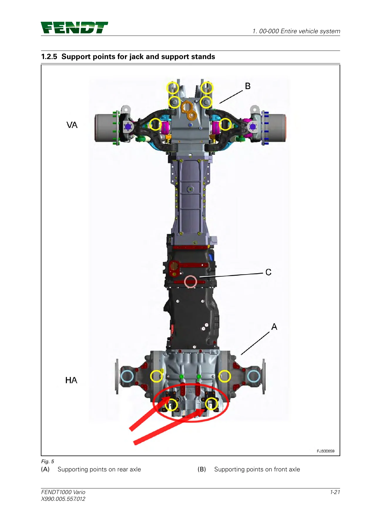
Chapter 1 opens with DANGER, WARNING and CAUTION definitions and a long briefing that applies before any repair. High-pressure hydraulic oil, residual brake-system air pressure after the engine is stopped, front-axle suspension accumulators that stay charged even with the engine off, hot coolant, battery electrolyte, running fans and PTO shafts are all called out with explicit release methods. Front-axle suspension pressure is relieved by screwing in the thumb screws on MVFS [Y064] (lower) and MVFH [Y065] (raise); the note states that the in-cab lock/lower command does not dump that pressure. Brake lines are relieved with the engine off by applying the foot brake at least ten times after the tractor is secured against rolling. High-pressure fuel work waits after shut-down; welding requires both battery terminals disconnected and the earth clamp close to the weld. Jacking diagrams mark rear-axle ring gears, trumpet housings and lower-link stands, front-axle housing and jib points, and the coupler-housing pad used when the rear axle is off. Open mounting faces on tractors without a rear power lift are marked as unsuitable for a jack.

IMAGES PREVIEW

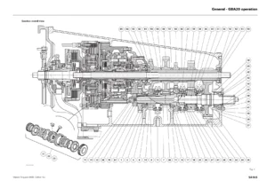
Fendt 1000 Vario S4 Workshop Service Manual 1038 1042 1046 1050 May 2018 — PDF page 1 preview
Fendt 1000 Vario S4 Workshop Service Manual 1038 1042 1046 1050 May 2018 — PDF page 24 preview
Fendt 1000 Vario S4 Workshop Service Manual 1038 1042 1046 1050 May 2018 — PDF page 28 preview

Calibration codes and fault tables

Settings and calibration occupy a large block in the entire-vehicle chapter. Codes documented include 1001 (crossgate lever), 1003–1006 (linear modules), 2401 (steering angle sensor), 2403 (VarioGuide steering valve), transmission codes 4001 clutch pedal, 4002 hand throttle, 4005 accelerator / driving pedal, 4007 transmission ratio characteristic, 4009 turbo-clutch function and 4010 driving pedal resolution, plus 6034 rear PTO clutch, 7666 front-axle suspension, 8001/8002 rear EPC and 9001/9002 front EPC. Matching calibration fault codes and a vehicle-wide fault-code catalogue (groups such as 00.0.00 through 20.1.00 in the contents) give cause text and remedy direction for sensors, valves, bus faults and power-limit conditions. Component-position lists keyed A through Y, plus socket maps, let a technician walk from a code to the physical part and its separation-point connector.

Hydraulics, compressed air and electrics in practice

After any steering or hydraulic intervention the manual requires a check against the printed test report. Pressure-test sheets for one and two variable-displacement pumps list measuring points M2–M5, ranges to 600 bar and the expected behaviour of auxiliary pump, load-sensing pump, pilot pressure and emergency steering pump. Pump commissioning insists the variable pump is filled through the leak-oil connection before first start, and transport spacers are removed. Compressed-air pages locate circuit reservoirs, the 4-circuit safety valve, front- and rear-axle wheel valves used by VarioGrip, and the hand-brake and steering-brake valves. Electrical pages give pin-out tables, frequency checks (for example rear PTO speed versus engine speed) and fuel low-pressure setpoints of 5.0 to 6.0 bar with return pressure 0 to 0.2 bar at the Fuel Service Centre points.

How to use this Fendt 1000 Vario workshop manual on the bench

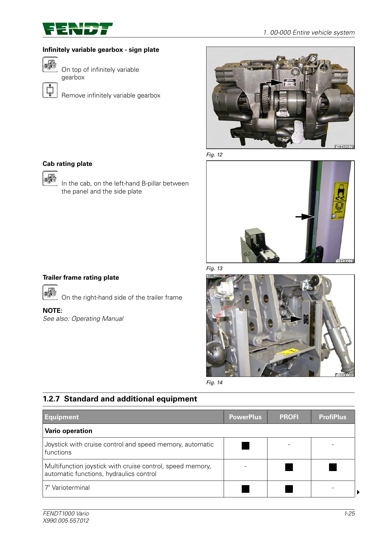
Start with the VIN and type plate locations (stamped chassis number on the right front frame, engine plates on both sides of the MAN engine, transmission plate on the right of the housing, Vario gearbox plate on top of the unit, cab plate on the left B-pillar). Confirm the tractor type against WAM531–WAM534 and the 527–530 chassis series on the cover. Release stored pressure as drawn, support the machine only at the marked points, then open the chapter for the assembly in work. Special tool numbers appear beside the jobs that need them (examples in the text include measurement module X899.980.319.100 and various adapter cables). After mechanical work the book still expects the matching calibration or pressure test before the tractor is released.

Get the manual and start the job

With the Fendt 1000 Vario S4 Workshop Service Manual 1038 1042 1046 1050 May 2018 on hand you can pressure-release the front-axle suspension and brake circuits, split the tractor at the front axle or clutch housing, service the MAN D2676 LE121 common-rail engine and SCR system, diagnose Vario hydrostatic drive and 4WD slip control, pressure-test load-sensing pumps, work VarioGrip and pneumatic brakes, run the listed calibration codes and interpret the fault-code tables instead of guessing. Using the printed sequences, torques and measuring-point values keeps high-pressure fuel, hydraulic and air systems inside the limits the book specifies and avoids damage from skipped pressure dumps or skipped calibrations. After payment the file is delivered as an instant PDF download — no shipping wait — ready to open on a workshop PC, tablet or phone and to print the pages needed at the machine.


Reviews

There are no reviews yet.

Be the first to review “Fendt 1000 Vario S4 Workshop Service Manual 1038 1042 1046 1050 May 2018”

What Our Customers Say

★★★★★ Live reviews from customers
Loading customer reviews...
0
    0
    Your Cart
    Your cart is emptyReturn to Shop
    🛒
    Recently Purchased
    🕒 verified order