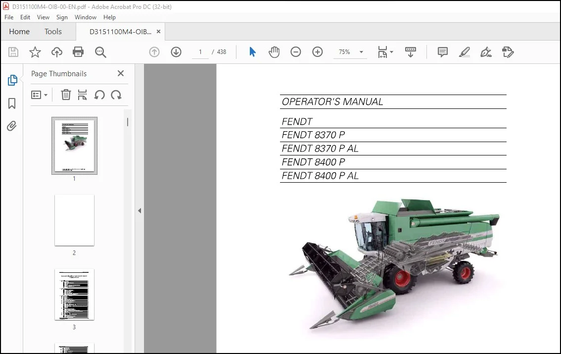
FENDT NA Harvesting 8370 P 8870 PA L 8400 P 8400 PA L Combines Series Operator’s Manual – PDF DOWNLOAD
Original price was: $78.00.$28.95Current price is: $28.95.
FENDT NA Harvesting 8370 P 8870 PAL 8400 P 8400 PAL Combines Series Operator’s Manual – PDF DOWNLOAD
D3151100M4 –
S/N 580010001
Description
FENDT NA Harvesting 8370 P 8870 PA L 8400 P 8400 PA L Combines Series Operator’s Manual – PDF DOWNLOAD
DESCRIPTION:
FENDT NA Harvesting 8370 P 8870 PA L 8400 P 8400 PA L Combines Series Operator’s Manual – PDF DOWNLOAD
1.1 Dear Customer
1.1.1 Appropriate Use
- This self-propelled combine harvester is manufactured exclusively for usual agricultural purposes (appropriate use). Any other use is considered as being contrary to the appropriate use. AGCO declines all liability in cases of physical damage or injuries resulting from non-appropriate use. The risk lies exclusively with the user.
- The conformity and strict adherence to the operating, maintenance and repair requirements specified by AGCO are also essential factors for appropriate use.
- This self-propelled combine harvester may be used, serviced and repaired only by personnel having full knowledge of its specific features and who are aware of the danger involved and the applicable safety rules (prevention of accidents).
- It is the responsibility of the owner/user to ensure that prescribed safety precautions and other general technical, health and safety and road-safety rules are observed.
- AGCO disclaims all liability to any claim resulting from the fitting of non-approved parts or accessories or unauthorised modification or alteration. Customers are strongly recommended to contact an AGCO dealer in the event of after-sale problems and for any adjustments that may be necessary.
1.1.2 Changes and Improvements
In accordance with the Company’s policy of continuous improvements to its products, alterations in the specifications may be made at any time without notice. The Company accepts no responsibility for any discrepancies which may occur between the specifications of its machines and the descriptions thereof contained in its publications.
1.1.3 Directives
Machinery directive This machine has been designed and produced in conformity with the Machinery Directive 2006/42/EC. An EC declaration of conformity is supplied with the machine upon delivery.
1.1.4 Preface
This Manual
- The purpose of this manual is to enable the owner/operator to handle and maintain the combine efficiently. Time spent in becoming familiar with the Operator’s Manual now will save time in the field . Wide variations in operation conditions make it impossible for the Company to make comprehensive or definite statements in its publications concerning performance and the use of its machines, or to accept liability for any damage which may result from errors or omissions.
- The specifications and illustrations contained in this manual pertain to combines manufactured for specific countries. Due to differing laws and requirements in various countries, some apparent discrepancies may result between any particular combine and those depicted in this manual. Some accessories and optional equipment appearing in this manual are not
- necessarily available in all territories. Technical specifications, dimensions and weights are without any obligation. Right to change technical specifications and equipment reserved. Front, rear, RH and LH are always seen in the travelling direction.
TABLE OF CONTENTS:
FENDT NA Harvesting 8370 P 8870 PA L 8400 P 8400 PA L Combines Series Operator’s Manual – PDF DOWNLOAD
1 General Information 11
1 1 Dear Customer 13
1 1 1 Appropriate Use 13
1 1 2 Changes and Improvements 13
1 1 3 Directives 13
1 1 4 Preface 14
1 1 5 EC Declaration of Conformity for Combine and Table 15
1 1 6 Product Identification 18
1 1 7 Sketch and parts identification 19
1 1 8 Disposal 20
2 Safety 23
2 1 Safety 25
2 1 1 General Safety Precautions 25
2 1 2 Attention – Warning Symbols 25
2 1 3 Safety Precautions 25
2 1 4 Road Transport 27
2 1 5 Warning/Instruction decals 28
2 1 6 CE Marking and Type Plate on the Combine 32
2 1 7 Position of CE Markings and Type Plate 41
3 Operation, Controls and Cab 45
3 1 Before Start 4 7
3 1 1 Before Start 47
3 2 Operator cab 49
3 2 1 Arrangement and Controls 49
3 2 2 Optional Extra 50
3 3 Safety Precautions – on the Move 51
3 3 1 Safety Precautions – on the Move 51
3 4 Starting and Stopping the Engine 52
3 4 1 Starting the engine 52
3 5 Drive Controls 55
3 5 1 Multifunction Lever 55
3 5 2 Adjustable Armrest and Control Panel 56
3 5 3 Change of Gears 57
3 5 4 Reduced Engine Revolutions in Road Transport (Speed Matching System) 58
3 5 5 Steering column 58
3 5 6 Brakes 59
3 6 Seats 60
3 6 1 Adjustment of Operator Seat 60
3 6 2 Adjustment of Air-Suspended Seat 60
3 6 3 EF declaration of conformity for the operator seat 61
3 6 4 Safety Switch in Operator Seat – (Operator Present Switch) 62
3 6 5 Safety belt 63
3 6 6 Passenger seat 63
3 7 Mirrors 64
3 7 1 Electrically adjustable rearview mirrors 64
3 8 Accessibility 65
3 8 1 Ladder for Cab 65
3 8 2 Ladder for Engine Compartment 65
3 8 3 Cleaning the Windscreens 66
3 9 Emergency Situations 68
3 9 1 Emergency Exit 68
3 9 2 Fire Extinguisher 69
3 10 Light and Lamps 70
3 10 1 Lights 70
3 10 2 Main Light and Work Light 71
3 11 Climate control 72
3 11 1 Maintenance and overview 72
3 11 2 Operation of climate control 73
3 12 Printer 75
3 12 1 Exchanging Paper and Ribbon in Printer 75
3 12 2 Inserting the Paper Roll 75
3 12 3 Fitting the Ribbon 76
3 13 Optional Extra 77
3 13 1 Four-Wheel Drive 77
3 13 2 Reversing camera 79
3 13 3 Auto-Steering 79
4 Operation, FIELDSTAR 81
4 1 Safety precautions 83
4 1 1 Safety precautions, Operating FIELDSTAR 83
4 2 FIELDSTAR 84
4 2 1 FIELDSTAR in general 84
4 2 2 Operating FIELDSTAR on Terminal 85
4 2 3 Operating the Terminal by Remote Control in the Multi-Function Lever 86
4 2 4 Contrast and Brightness Control 87
4 2 5 Cleaning of terminal 87
4 2 6 Data card 88
4 2 7 FIELDSTAR Menu Structure 88
4 3 Harvest Menu 90
4 3 1 Instrument Reading 90
4 4 Main Menu 94
4 4 1 Main menu structure 94
4 5 Monitoring 96
4 5 1 Monitoring in general 96
4 5 2 Shaft Speeds 97
4 5 3 Engine Monitoring/Alarm 97
4 5 4 Engine Safety Alarm 97
4 5 5 Information 98
4 5 6 Shaft Speeds 99
4 6 Harvesting Data 100
4 6 1 Standard data 100
4 6 2 Data Logging in General 101
4 6 3 Using Data Logging 102
4 6 4 Data Logging Setup 109
4 6 5 Using Markers 112
4 7 Operator’s Manual 113
4 7 1 Harvest Settings 113
4 7 2 Routine Servicing 114
4 7 3 FIELDSTAR 114
4 8 Diagnostics 115
4 8 1 Troubleshooting in FIELDSTAR 115
4 9 Coding 121
4 9 1 Codingingeneral 121
4 9 2 Clock Adjustment 122
4 9 3 Language 122
4 9 4 Area Measuring 122
4 9 5 Table Calibration 124
4 9 6 Returns Volume 125
4 9 7 Grain Loss Monitor 125
4 9 8 Shaft alarm calibration 125
4 9 9 Concave Calibration 126
4 9 10 Constant Flow 126
4 9 11 Wheel Track and Auto Level Combine 126
4 9 12 Coding of Electrical Straw Deflectors 127
4 9 13 Lead Time and Lag Time 129
4 9 14 Calibration of actuator for electrical sieves 130
4 10 Settings 131
4 10 1 Harvest Settings 131
4 10 2 Table Settings 134
4 10 3 Machine Settings 136
4 11 Returns Volume Monitor 139
4 11 1 Returns volume 139
4 11 2 Coding 139
4 12 Grain Loss Monitoring 141
4 12 1 Sensors 141
4 12 2 Adjustment of Grain Loss Sensors 141
4 13 Shaft Alarm Limits 143
4 13 1 Shaft Alarm Calibration 143
4 14 Yield meter 144
4 14 1 Yield Meter (Isotopic) 144
4 14 2 Micro-Trak Yield Meter 146
4 14 3 Yield Meter Calibration 148
4 15 Moisture meter 150
4 15 1 Limitations in the use of the moisture meter 150
4 15 2 Continuous Moisture Measuring 150
4 15 3 Measuring Principle 150
4 15 4 Using the Moisture Meter 151
4 15 5 Cleaning the Moisture Meter, 151
4 15 6 Calibration of moisture meter 152
4 16 Cutting height control 154
4 16 1 Adjustment and operation of cutting height control 154
4 16 2 Coding of table 157
4 17 Field pressure control 158
4 17 1 Adjustment and operation of field pressure control 158
4 18 Interaction between the Table Controls 160
4 18 1 Table controls, an outline 160
4 19 Auto Level Table 162
4 19 1 Principle of Auto Level table 162
4 19 2 Bleeding 163
4 19 3 Coding of Auto Level Table 164
4 19 4 Calibration of Table Angle 164
4 20 Operation of Auto Level Table 166
4 20 1 Using the Auto Level Table 166
4 21 Ground sensors 168
4 21 1 Checking and Adjusting the Ground Sensors 168
4 22 Constant Flow 170
4 22 1 Constant Flow functional description 170
4 22 2 Start-up and Adjustment of Constant Flow 171
4 22 3 Constant Flow Engagement 173
5 Operation, Auto Level Combine 175
5 1 Safety precautions 177
5 1 1 Safety precautions, operation of Auto Level Combine 177
5 1 2 Safety System 177
5 2 Attachment of Auto Level Table 178
5 2 1 Attachment of Table to Auto Level Combine 178
5 3 Combinations 179
5 3 1 Automatically or manually 179
5 3 2 Selecting Combination 179
5 3 3 Combinations for Auto Level combine and Auto Level table 179
5 3 4 Priority of hydraulic functions 181
5 4 Auto Level 182
5 4 1 Auto Level combine 182
FENDT 8370 P – 8400 P – EAME 5
D3151100M4 – SIN 580010001
Table of contents
5 4 2 Manual Control of Auto Level Combine 182
5 5 Auto Level Combine/Table 183
5 5 1 Combine 183
5 5 2 Transport 184
5 5 3 Auto Level Table 185
5 6 Calibration 186
5 6 1 Calibration of Auto Level Combine 186
5 6 2 Errors during Calibration 187
5 7 Coding 188
5 7 1 Coding of Auto Level Table 188
5 7 2 Zero Cutting Height 188
5 8 Safety System 189
5 8 1 Safety System, Auto Level 189
5 8 2 Automatic Control of the Tilt Sensor Function 189
5 8 3 About the system 190
5 8 4 Hose Breach Protection for Auto Level Hydraulics 190
5 9 Troubleshooting 191
5 9 1 Trouble shooting in general 191
5 9 2 Machine Not Levelling Correctly 192
5 10 Servicing and User Tips 194
5 10 1 Retrofit of new FIELDSTAR Auto Level Job Computer and Sensors 194
5 10 2 Unintentional Use of Manual Keys in Automatic Mode 194
5 10 3 Diagnostics – Auto Level Combine Functions and Sensors 195
6 Motor 197
6 1 Safety precautions 199
6 1 1 Safety Precautions, Engine 199
6 2 Engines 200
6 2 1 Engine Types 200
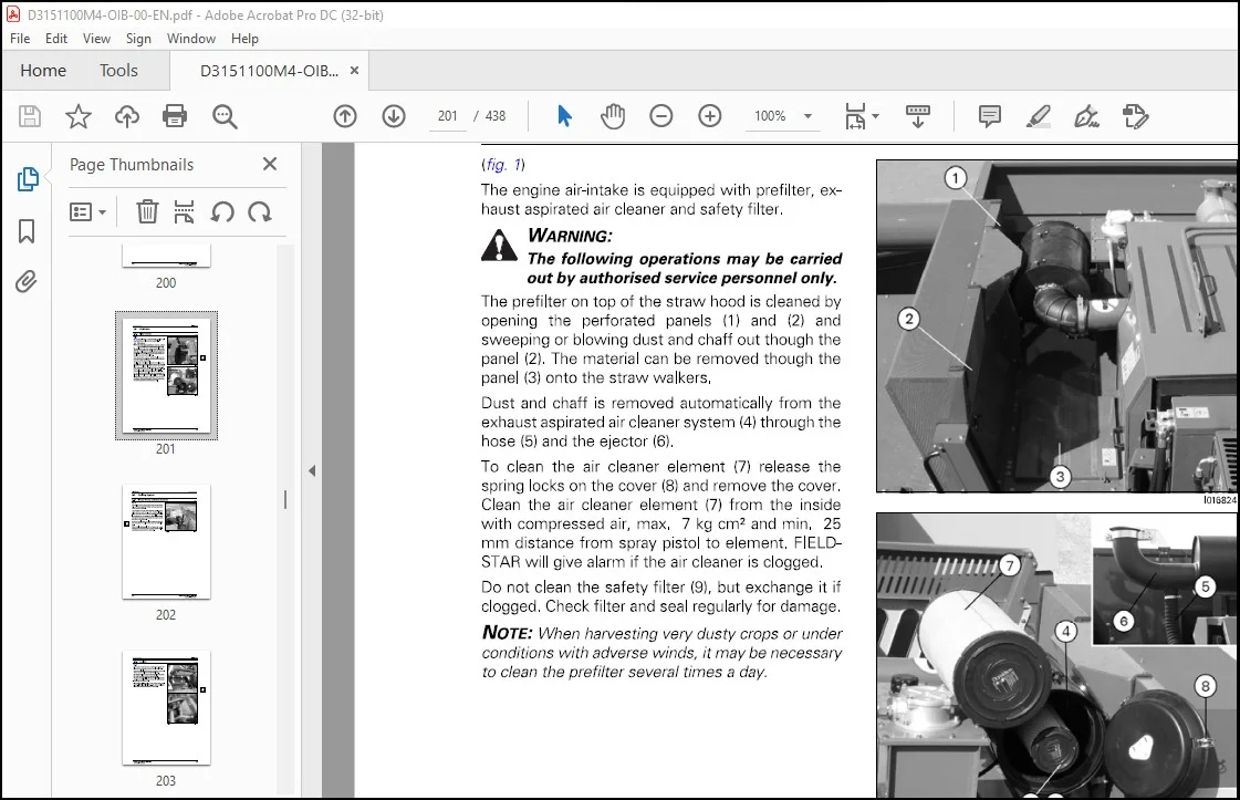
6 3 Air-intake 201
6 3 1 Filter system 201
6 4 Cooling System 202
6 4 1 Rotary Screen and Dust Aspirator 202
6 4 2 Coolers 203
6 4 3 Coolant 204
6 4 4 Checking the Fan Belt Tension 204
6 5 Fuel System 205
6 5 1 Fuel system 205
6 5 2 Filter Change 206
6 6 Engine oil/change 207
6 6 1 Oil and Filter Change 207
6 7 Cleaning 208
6 7 1 Cleaning of engine compartment 208
6 8 EEM3 Engine Management 209
6 8 1 Electronic Engine Management 209
6 8 2 Engine Trouble Shooting (Self-Diagnosis) 210
6 8 3 EEM3 codes 211
7 Cutting Tables 217
7 1 Safety precautions 219
7 1 1 Safety Precautions, Cutting Tables 219
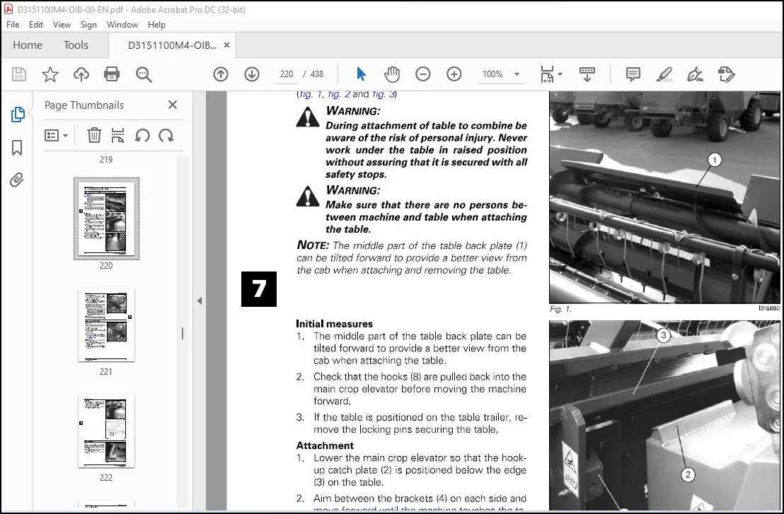
7 2 Attachment/Removal of Table 220
7 2 1 Attachment of Table, Standard and Auto Level 220
7 2 2 Removal of Table 221
7 2 3 Supports 222
7 3 Table trailer 223
7 3 1 Attachment of combine and trailer 223
7 3 2 Table Trailer Brakes 223
7 4 Reel 224
7 4 1 Reel Adjustment Up/Down, Fore/Aft 224
7 4 2 Bleeding 225
7 4 3 Reel Rotation 225
7 4 4 Reel tine bars
7 4 5 Adjustment of the Reel in the Table
Knife
7 5 1 Knife and knife drive
Feeding
7 6 1 Table auger
7 6 2 Cut-off strip and distribution strip
7 6 3 Replacement of Feathering Fingers
7 6 4 Auger Flight Extensions, 20-22-25-30′ Tables
7 6 5 Reversing
Transmission
7 7 1 PowerFlow Table, Knife Drive and Table Auger
7 7 2 Slip Clutch for Table Auger
PowerFlow Table
7 8 1 PowerFlow belts
7 8 2 Inspection and Start-Up of PowerFlow Belts
7 8 3 Adjustment of belts
7 8 4 Scrapers, front
7 8 5 Scrapers, Rear, and Adjustment of Bearing Housings
7 8 6 Table bottom
7 8 7 Cleaning
Crop Lifters
7 9 1 Using Crop Lifters
Vertical Knives, Rape Auger and Straw Dividers
7 10 1 Vertical knife
7 10 2 Mounting of Vertical Knife
7 10 3 Rape auger
7 10 4 Folding torpedo dividers and bow dividers
7 10 5 Mounting of Straw Dividers
7 10 6 Adjustment of Torpedo Divider
Fixed Fingers
7 11 1 Fitting of fixed table auger fingers
7 11 2 Using Fixed Table Auger Fingers
7 11 3 High Table Sides
Main crop elevator
7 12 1 Elevator Chain
7 12 2 Transmission for Table
7 12 3 Stone Trap
7 12 4 Initial Adjustment of Cutting Height Indication
8 Operation of Table and Threshing Unit 247
8 1 Safety precautions 249
8 1 1 Safety Precautions, Operation of Machine and Cutting Table 249
8 2 Operation of Table 251
8 2 1 Table Height and Table Automatic Control 251
8 2 2 Cutting Height Control 252
8 2 3 Field Pressure Control 253
8 2 4 Preset cutting height 254
8 2 5 Auto Level Table 254
8 2 6 Table Engagement – Emergency Stop 255
8 3 Threshing Unit Transmission 256
8 3 1 Threshing unit engagement 256
8 3 2 Cylinder Variator 257
8 3 3 Turning Tool for Cylinder 257
8 4 Concave Setting, Electrically Adjustable 258
8 4 1 Operation of Concave 258
8 4 2 Concave Setting 258
8 5 Threshing 260
8 5 1 Concave filler plates 260
8 5 2 Straw walkers 260
8 5 3 Rear beater curtain 261
FENDT 8370 P – 8400 P – EAME 7
D3151100M4 – SIN 580010001
Table of contents
8 6 Straw Chopper and Spreader Hood 262
8 6 1 Straw chopper 262
8 6 2 Adjustment of Spreader Hood 264
8 6 3 Counter Knives and Cross Bar 265
8 6 4 Replacement of Knives 267
8 7 Fanning Mill and Sieves 268
8 7 1 Fanning mill 268
8 7 2 Shaker shoe 268
8 7 3 Shaker Shoe with Electrical Sieves 269
8 7 4 Manual Adjustment of Sieves 269
8 7 5 Cleaning of Sieves and Main Grain Pan 270
8 7 6 Cleaning the Sieves 271
8 7 7 Shaker Shoe Light 273
8 7 8 Special sieves 273
8 8 Internal Grain Transport 274
8 8 1 Auger Housing/Elevators 274
8 8 2 Returns thresher 274
8 8 3 Tank filling auger 275
8 8 4 Grain tank 276
8 8 5 Unloading auger 278
8 8 6 Unloading Auger Clutch 279
8 8 7 Unloading tube 280
8 9 Rotary Separator 281
8 9 1 Adjusting the revolutions 281
8 9 2 Concave setting 282
8 10 Straw hood 283
8 10 1 Alarm switch for straw hood blocked 283
8 10 2 Light in straw hood 284
8 11 Chaff spreader 285
8 11 1 Setting 285
8 12 Maxi Spreader 287
8 12 1 Operation and Adjustment 287
8 12 2 Adjustment of Sensors 288
8 13 Maize Threshing 289
8 13 1 Maize Threshing in General 289
8 13 2 Attachment of Maize Header 289
8 13 3 Area measuring 290
8 13 4 Main crop elevator 290
8 13 5 Concave/Initial Settings 291
8 13 6 Threshing cylinder 291
8 13 7 Rotary Separator 291
8 13 8 Shaker shoe 292
8 13 9 Straw walkers 292
8 13 10 Bottom auger cover plate 293
8 13 11 Scrapers 293
8 13 12 Rear beater curtain 293
8 13 13 Straw chopper 294
8 13 14 Maxi Spreader 294
8 14 Harvest settings 295
8 14 1 Harvest charts and settings 295
8 15 Threshing 297
8 15 1 Threshing Directions 297
9 Transmissions 299
9 1 Safety precautions 301
9 1 1 Safety Precautions, Transmissions 301
9 2 Adjustment of Transmissions 302
9 2 1 General 302
9 2 2 Threshing unit clutch 302
9 2 3 Hydrostatic transmission 303
9 3 Transmissions 304
9 3 1 Rear beater 304
8 FENDT 8370 P – 8400 P – EAME
D3151100M4 -SIN 580010001
Table of contents
9 3 2 Crop Elevator and Table 304
9 3 3 Straw chopper 305
9 3 4 Threshing cylinder 305
9 3 5 Unloading auger 306
9 3 6 Shaker Shoe and Chaff Spreader Counter Drive, and Straw Walker Drive 307
9 3 7 Filling and Returns System Countershaft 308
9 3 8 Returns Elevator and Returns Thresher 308
9 3 9 Tank Filling Elevator and Tank Filling Auger 309
9 3 10 Dust aspirator 309
9 3 11 Rotary screen 310
9 3 12 Fanning mill 311
9 3 13 Rotary Separator 311
9 3 14 Alternator and Fan 312
9 3 15 Climate control 312
9 4 Transmission Diagrams 313
9 4 1 Transmission Diagram, Left-Hand Side 313
9 4 2 Transmission Diagram, Right-Hand Side 315
10 Hydraulics 317
10 1 Safety precautions 319
10 1 1 Safety Precautions, Hydraulic System 319
10 2 Hydraulic System 320
10 2 1 Hydraulic system, standard combine 320
10 2 2 Hydraulic System, Four-Wheel Drive 321
10 3 Oil change 322
10 3 1 Draining and refilling hydraulic oil 322
10 4 Filter Change 323
10 4 1 Filter change in general 323
10 4 2 Return Oil Filter 323
10 4 3 Storage of Hydraulic System 324
10 5 Auxiliary Hydraulics 325
10 5 1 Auxiliary hydraulics in general 325
10 5 2 Functions and Auxiliary Hydraulics 325
10 5 3 Reel Adjustment Fore/Aft – Up/down 325
10 6 Hydraulic diagrams 326
10 6 1 Hydraulics Diagram, Standard Combine 326
10 6 2 Hydraulics Diagram, Auto Level Combine 329
10 6 3 Hydraulics Diagram for Chaff Spreader 331
10 6 4 Hydraulics diagram for Maxi Spreader 332
11 Maintenance 335
11 1 Safety precautions 337
11 1 1 Safety Precautions, Maintenance 337
11 2 Undercarriage 339
11 2 1 Undercarriage in general 339
11 2 2 Wheel Nut Torques 339
11 2 3 Tyre Pressure 339
11 3 Lubrication Intervals 341
11 3 1 Lubrication chart, time intervals 341
11 3 2 Lubrication chart, right- and left-hand side 344
11 3 3 Lubrication chart, main crop elevator and front axle 346
11 3 4 Lubrication points, left-hand machine side 347
11 3 5 Lubrication points, right-hand machine side 361
11 3 6 Lubricants and Operating Fluids 372
11 3 7 Preliminary Service Inspections 373
11 3 8 Maintenance Required 374
11 4 Oil Change, Gear 377
11 4 1 Gearbox 377
11 4 2 Final drives 377
11 4 3 Right-angle gear for returns thresher 378
11 5 Climate control 379
11 5 1 Diagram for Climate Control System 379
FENDT 8370 P – 8400 P – EAME 9
D3151100M4 – SIN 580010001
Table of contents
11 5 2 Maintenance 379
11 6 Cleaning and Off-Season Storage 380
11 6 1 Cleaning 380
11 6 2 Off-season Storage 381
11 6 3 Storage of Engine, Fuel System and Hydraulic System 382
11 6 4 Periodical Start-Up 382
11 6 5 Removal of Crop Elevator 383
11 6 6 Removal of Elevator Chains 383
11 6 7 After Off-Season Storage 383
11 7 Adjustment of Brakes 384
11 7 1 Adjustment of Foot Brakes, Disc Brakes 384
11 7 2 Adjustment of Parking Brake 384
12 Electrical System 385
12 1 Safety precautions 387
12 1 1 Safety Precautions, Electric System 387
12 2 Electrical System 388
12 2 1 Charging system 388
12 2 2 Electric Boxes and Main Switch 389
12 2 3 External connectors 12V 390
12 3 Electro-Hydraulic System 392
12 3 1 Electro-Hydraulic System in general 392
12 4 Key to Signatures for Wiring Harness 393
12 4 1 Wire Codes 393
12 4 2 Component Codes 393
12 5 Overview, Electric Box and Cab 394
12 5 1 Position of Connectors in Electric Boxes 394
12 5 2 Fuses and Relays, Electric Box and Cab 395
12 6 Wiring diagrams 397
12 6 1 Key to symbols 397
12 6 2 Diagrams overview 398
12 6 3 Fuse Ratings 398
12 6 4 Components 399
12 6 5 Wiring diagrams 407
13 Specifications 421
13 1 Specifications 423
13 1 1 Dimensions and specifications 423
1 1 Dear Customer 13
1 1 1 Appropriate Use 13
1 1 2 Changes and Improvements 13
1 1 3 Directives 13
1 1 4 Preface 14
1 1 5 EC Declaration of Conformity for Combine and Table 15
1 1 6 Product Identification 18
1 1 7 Sketch and parts identification 19
1 1 8 Disposal 20
IMAGES PREVIEW OF THE MANUAL:
Questions? Email us: [email protected]
PLEASE NOTE:
- This is the SAME MANUAL used by the dealerships to diagnose your vehicle
- No waiting for couriers / posts as this is a PDF manual and you can download it within 2 minutes time once you make the payment.
- Your payment is all safe and the delivery of the manual is INSTANT – You will be taken to the DOWNLOAD PAGE.
- So have no hesitations whatsoever and write to us about any queries you may have : heydownloadss @gmail.com
S.M