Trusted Business
Verified & Licensed
Virus Free Files
100% Safe Downloads
Secure Payment
SSL Protected
Instant Delivery
Available Immediately
Fiat Hitachi CRAWLER DOZER D180 LGP D180 Power Steering Workshop Manual – PDF DOWNLOAD
$28.95
Fiat Hitachi CRAWLER DOZER D180 LGP D180 Power Steering Workshop Manual – PDF DOWNLOAD
Instant PDF Download
Available immediately
Save to Your Device
Download & keep forever
Antivirus Scanned
100% virus-free
Trusted Worldwide
175,000+ customers
Description
Fiat Hitachi CRAWLER DOZER D180 LGP D180 Power Steering Workshop Manual – PDF DOWNLOAD
FILE DETAILS:
Fiat Hitachi CRAWLER DOZER D180 LGP D180 Power Steering Workshop Manual – PDF DOWNLOAD
Language : English
Pages : 288
Downloadable : Yes
File Type : PDF
DESCRIPTION:
Fiat Hitachi CRAWLER DOZER D180 LGP D180 Power Steering Workshop Manual – PDF DOWNLOAD
SAFETY RULES
– Check monitoring instruments at start-up and frequently during operations. in case the brake pressure gauge shows a pressure lower than the minimum operating pressure, stop immediately the machine .
– DO NOT CARRY RIDERS ON MACHINE – Study and familiarise with escape routes alternate to normal exit routes. – Seat belts are required by current regulations to be provided with Roll Over Protection Structures or cabs. Keep safety belts fastened around you during operation.
– For your personal protection, do not climb on or off machine while machine is in motion.
– Make sure that exposed persons in the area of operation are clear of the machine, before starting the engine and operating the equipment. Sound horn. Obey all indications provided by flags and signals.
– NEVER COAST the machine down grades and slopes with the transmission in neutral or neutralised. Choose and shift into the most appropriate gear to keep the speed required, thus preventing any loss of control.
– Do not operate machinery in a condition of extreme fatigue or illness. Be especially careful towards the end of working shift.
– Do not operate machine with brakes out of adjustment.
– Operate the machine at speeds slow enough to ensure complete control at all times.
– Travel slowly over rough terrain, on slopes or near dropoffs, in congested areas or on ice or slippery surfaces.
– When backing, always look to where the machine is to be moved. Be alert to the position of exposed personnel. DO NOT OPERATE if exposed personnel enter the immediate work area. STOP THE MACHINE.
Maintain a safe distance from other machines. Provide sufficient clearance for ground and visibility conditions. Yield right-of-way to loaded machines.
– Maintain clear vision of areas of travel or work. Keep cab windows clean and repaired. – When machines are operating in tandem, the pusher (rear) must be equipped with the appropriate deflectors to protect the unit in front from the air stream coming from the radiator.
– When pulling or towing through a cable or chain, do not start suddenly at full throttle; take-up slack carefully. Inspect carefully for flaws or troubles before using.
– Avoid kinking chains or cables. Do not pull through a kinked chain or cable to the high stresses and possibility of failure of the kinked area. Always wear heavy gloves when handling chains or cables.
IMAGES PREVIEW OF THE MANUAL:
TABLE OF CONTENTS:
Fiat Hitachi CRAWLER DOZER D180 LGP D180 Power Steering Workshop Manual – PDF DOWNLOAD
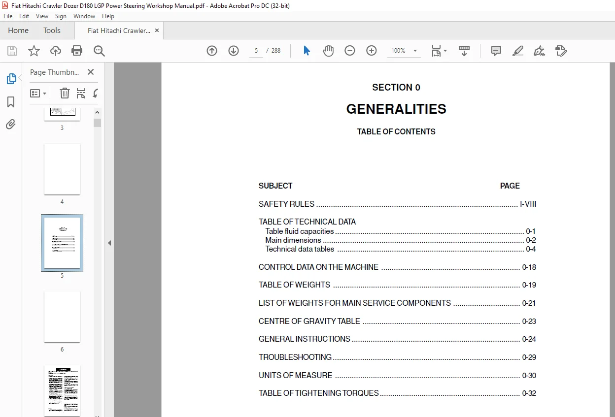
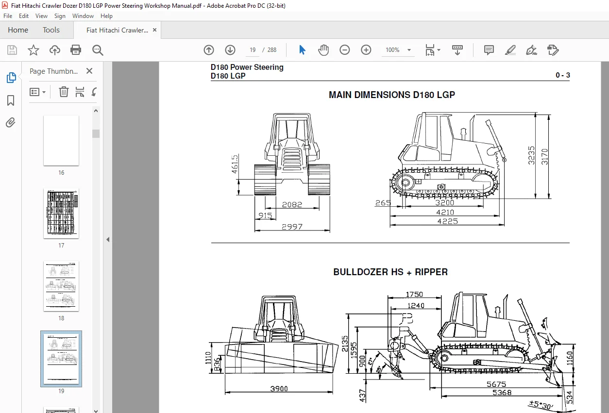
D180 Power Steering D180 LGP....................................................  1
SUMMARY.........................................................................  3
	GENERALITIES................................................................  5
		SAFETY RULES............................................................  8
		TECHNICAL DATA TABLES................................................... 15
		TABLE OF FLUID CAPACITIES............................................... 17
		MAIN DIMENSIONS......................................................... 18
		TECHNICAL DATA.......................................................... 20
		CONTROL DATA ON THE MACHINE............................................. 34
		TABLE OF WEIGHTS ....................................................... 35
		LIST OF WEIGHTS FOR MAIN SERVICE COMPONENTS............................. 37
		CENTRE OF GRAVITY TABLE................................................. 39
		GENERAL INSTRUCTIONS.................................................... 40
		TROUBLESHOOTING......................................................... 45
		UNITS OF MEASURE........................................................ 46
		TABLE OF TIGHTENING TORQUES............................................. 48
	ENGINE...................................................................... 49
		GENERAL SPECIFICATIONS.................................................. 51
		SERIES "C" ENGINE DATA.................................................. 53
		DIAGRAMS OF SERIES "C" ENGINE........................................... 56
		MOUNTING OF ENGINE ON FRAME............................................. 59
		THROTTLE LINKAGE........................................................ 60
	TRANSMISSION................................................................ 61
		2.1 GENERAL DESCRIPTION................................................. 62
		Transmission housing.................................................... 64
		TROUBLESHOOTING......................................................... 65
		TESTS................................................................... 69
		TRANSMISSION GEARSHIFTING ELECTRIC CONTROL VALVE........................ 70
		PROCEDURES FOR THE REPAIR OF THE TORQUE CONVERTER....................... 71
		RE-INSTALLATION......................................................... 72
		DISASSEMBLY............................................................. 73
		REASSEMBLY.............................................................. 82
		PROCEDURES FOR THE REPAIR OF THE TRANSMISSION........................... 83
		RE-INSTALLATION......................................................... 84
		DISASSEMBLY............................................................. 85
		OVERHAUL OF THE FORWARD SPEED CLUTCH.................................... 99
		OVERHAUL OF THE 3rd SPEED...............................................101
		OVERHAUL OF THE REV SPEED CLUTCH........................................106
		MODULATING VALVES (Disassembly / Assembly)..............................110
		PRESSURE RELIEF VALVE (Disassembly / Assembly)..........................111
		2.6 SPECIFICATIONS AND DATA.............................................114
		TIGHTENING TORQUES (TORQUE CONVERTER)...................................115
		TRANSMISSION HOUSING....................................................116
		TRANSMISSION DATA.......................................................117
		TRANSMISSION CLUTCH DISC................................................119
		LUBE OIL PRESSURE RELIEF VALVE..........................................120
		FORWARD REVERSE MODULATING VALVES.......................................121
		TRANSMISSION PRESSURE RELIEF VALVE AND TORQUE CONVERTER SAFETY..........122
		TORQUE CONVERTER / TRANSMISSION FEEDING PUMP............................123
		OIL FILTERS.............................................................124
	FINAL DRIVES................................................................125
		3.1 GENERAL DESCRIPTION.................................................127
		FINAL DRIVE.............................................................128
		REPAIR PROCEDURES.......................................................130
		PULLING THE HOUSING COVER...............................................134
		DRIVEN GEAR.............................................................135
		DESCRIPTION OF INSTALLATION OF FRONT SEALS (LONG LIFE)..................136
		FINAL DRIVE (assembly)..................................................137
		SPECIFICATIONS AND DATA.................................................146
	BRAKES AND STEERING CLUTCHES................................................149
		GENERAL DESCRIPTION.....................................................150
		BRAKE CIRCUIT MAIN COMPONENTS...........................................151
		Brake powering valve block..............................................152
		Brake pedal valve.......................................................153
		Brake oil filter........................................................155
		STEERING HYDRAULIC CIRCUIT DIAGRAM......................................156
		STEERING CIRCUIT MAIN COMPONENTS........................................158
		Steering piloting valve block...........................................159
		TROUBLESHOOTING.........................................................160
		TESTS...................................................................162
		BRAKE PEDAL ADJUSTMENT..................................................163
		TEST AND SETTING OF BRAKE POWERING VALVE BLOCK..........................164
		CALIBRATION OF STEERING LEVERS..........................................165
		REPAIR PROCEDURES.......................................................167
		BRAKE POWER PUMP........................................................168
		BRAKES AND STEERING DIFFERENTIAL........................................169
		Removal of the ring gear................................................173
		Disassembly of the planet carrier differential assembly.................175
		Disassembly of the brake assembly.......................................176
		Re-assembly of the brake drum assembly..................................180
		CHECK AND INSPECTION OF BRAKE PACKS.....................................186
		Re-assembly of the sun gear.............................................187
		Re-assembly of the planet carrier assembly..............................188
		Re-assembly and re-installation of the ring gear assembly...............190
		Install the retaining circlip in the seat, using appropriate pliers.....191
		BEVEL GEAR SET (Removal/disassembly of pinion and bevel gear)...........193
		PROCEDURE FOR THE SETTING OF THE BEVEL PINION BEARINGS PRE-LOAD.........203
		PROCEDURE FOR THE SETTING OF THE BEVEL GEAR CROWN.......................204
		RE-INSTALLATION OF HOUSING COVER........................................205
		SPECIFICATIONS AND DATA.................................................206
		BRAKES..................................................................208
		BRAKE PEDAL VALVE.......................................................209
	UNDERCARRIAGE...............................................................213
		GENERAL DESCRIPTION.....................................................215
		MAIN COMPONENTS.........................................................216
		TROUBLESHOOTING.........................................................219
		INSPECTIONS.............................................................220
			INSPECTION AND ADJUSTMENT OF TRACK CHAINS...........................220
			SETTING OF THE TRACK TENSIONER PRESSURE RELIEF VALVE................221
		REPAIR PROCEDURES.......................................................222
			TRACK CHAIN.........................................................222
			REPLACING A DAMAGED LINK AND RE-INSTALLATION........................224
			IDLER (Removal/Re-installation/Overhaul)............................226
			A TRACK CHAIN SUPPORT ROLLERS (Removal/Installation/Overhaul).......229
			TRACK CHAIN BOTTOM ROLLERS (Removal / Installation / Overhaul)......231
		SPECIFICATIONS AND DATA.................................................235
		SPROCKETS...............................................................236
		BOTTOM ROLLERS..........................................................237
		SUPPORT ROLLERS.........................................................238
		TRACK TENSIONER DEVICE..................................................239
		FRONT CROSS-MEMBER PIVOTS...............................................240
		WEAR LIMITS.............................................................244
	DOZING EQUIPMENT HYDRAULIC SYSTEM...........................................245
		GENERAL DESCRIPTION.....................................................246
			OPERATION OF THE HYDRAULIC SYSTEM...................................246
			DOZER EQUIPMENT HYDRAULIC SYSTEM DIAGRAM............................248
		TESTS...................................................................250
			USE OF THE FLOW METER...............................................250
			FLOW TEST IN SINGLE CIRCUITS........................................250
		REPAIR PROCEDURES.......................................................251
			HYDRAULIC OIL RESERVOIR (Removal / Installation)....................251
			EQUIPMENT HYDRAULIC PUMP............................................253
			HYDRAULIC CONTROL VALVE (Removal/Disassembly/Overhaul)..............254
			Installation of blade...............................................255
		SPECIFICATIONS AND DATA.................................................256
			HYDRAULIC CONTROL VALVE.............................................256
			HYDRAULIC POWER PUMP................................................257
			BLADE LIFTING CYLINDER BALL JOINT...................................258
			BLADE LIFTING CONTROL CYLINDER......................................259
			BLADE TILT CONTROL CYLINDER (Bulldozer version).....................260
			BLADE TILT CONTROL CYLINDER (Angledozer version)....................261
			RIPPER CYLINDER.....................................................262
			BLADE PUSH ARMS AND RODS............................................263
			FRAME AND RODS......................................................264
			RIPPER LINKAGE......................................................265
	ELECTRICAL SYSTEM...........................................................267
		SAFETY RULES............................................................268
		ELECTRICAL DIAGRAM OF PROTECTION TREE...................................269
		FUSES...................................................................270
		LINK" FUSES AND COLD STARTING FUSE......................................271
		MAIN SWITCH.............................................................272
		ENGINE STARTING SWITCH..................................................272
		BACK-UP ALARM...........................................................273
		STARTER MOTOR...........................................................273
		INSTRUMENT PANEL / MONITOR..............................................274
		MONITOR SENDERS.........................................................277
		DISPLAY.................................................................281
		BUZZER..................................................................283
		RELAY - DIODES - DIVERTER BOX GROUP.....................................284
		MAIN CONNECTORS 19 - 21 - 23 WAYS.......................................287
Need help? Contact: [email protected]
PLEASE NOTE:
- This is the same manual used by the DEALERSHIPS to SERVICE your vehicle.
- The manual can be all yours – Once payment is complete, you will be taken to the download page from where you can download the manual. All in 2-5 minutes time!!
- Need any other service / repair / parts manual, please feel free to contact us at heydownloadss @gmail.com . We may surprise you with a nice offer
S.M