
Fiat-Hitachi EX135W Excavator Workshop Manual 604.06.991 (2000) – Complete Repair & Service PDF
Original price was: $39.95.$23.95Current price is: $23.95.
The complete Fiat-Hitachi EX135W Excavator Workshop Manual (2000), document 604.06.991, covering engine, hydraulic, electrical, undercarriage, front attachment, troubleshooting and performance testing. Approximately 996 pages, instant PDF download.
Description
Fiat-Hitachi EX135W Excavator Workshop Manual 604.06.991 (2000) – Complete Repair & Service PDF
The Fiat-Hitachi EX135W Excavator Workshop Manual is the definitive service and repair resource for the EX135W wheeled excavator, published by Fiat-Hitachi Excavators S.p.A. under document number 604.06.991 in 2000. This complete workshop manual equips skilled technicians with everything needed to diagnose, repair, maintain, and overhaul the EX135W machine, spanning engine systems, hydraulic circuits, electrical components, undercarriage assemblies, front-end attachments, and more. Whether you are performing routine maintenance, troubleshooting a fault, or undertaking a full component rebuild, this manual delivers the procedures, specifications, and technical data required to get the job done correctly.
File Details
- Manual Type: Workshop Manual (Service, Repair & Maintenance)
- Brand: Fiat-Hitachi
- Model: EX135W Excavator
- Document Number: 604.06.991
- Publication Year: 2000
- Language: English
- File Format: PDF
- Page Count: Approximately 996 pages
- Publisher: Fiat-Hitachi Excavators S.p.A., Product Support – Documentation Centre
Chapters Covered
- Section 1 – How to Use: Sections and Groups Indexes; Introduction; Manual Handling; Symbols and Indications; Features of the Manual
- Section 2 – Safety Rules: General Information; Safety Rules; Safety Decals
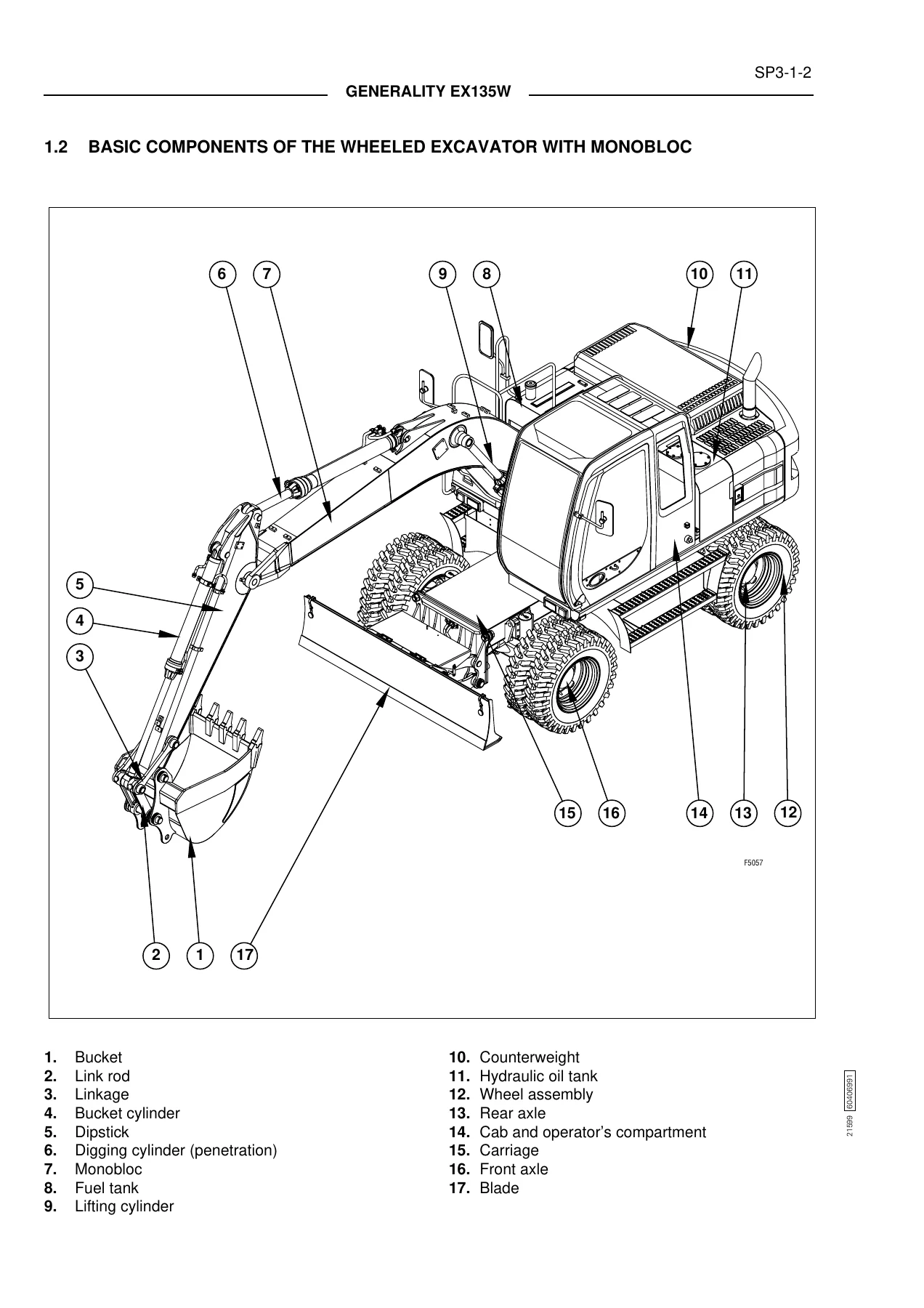
- Section 3 – Specifications: Generality; Basic Components of the Wheeled Excavator; Identification Data; Technical Specifications; Engine; Hydraulic System; Drive Line; Controls; Axles; Uppertructure Swing; Brakes; Steering System; Electrical System; Tires; Operating Weights; Dimensions; Digging Performances; Bucket Usefulness; Lifting Capacity; Filling Chart
- Section 4 – Superstructure: Main Frame and Counterweight; Engine Group; Hydraulic Oil Reservoir; Fuel Reservoir; Covers and Protections; Cab Group; Cab Heater; Cab Electric Components; Chassis Electric Components; Superstructure Maintenance; Hydraulic Pumps (O/P & D/A); Control Valve (O/P & D/A)
- Section 5 – Undercarriage: Outlines; Lower Frame; Swing Bearing; Travel Unit; Wheels; Blade Assembly; Lateral Stabilizers; Hydraulic Hoses and Undercarriage Components; Travel Hydraulic Motor (O/P & D/A); Transmission (O/P & D/A); Axles (O/P & D/A); Transmission Shaft (O/P & D/A)
- Section 6 – Front-End Attachment: Boom Assembly; Arm Assembly; Bucket Assembly; Front Pipings; Maintenance Standard; Hydraulic Cylinders (O/P & D/A); Pins and Bushings
- Section 7 – Hydraulic System: Generalities; Main Hydraulic System; Pilot/Brakes System; Steering System; Brakes System; Operation of Circuits; Travel Circuit; Hydraulic System Diagram
- Section 8 – Electrical System: Safety Rules; Specifications and Data; Location and Functions of Components; Arrangements and Operation; Electronic Control Units and Diodes; Electric Components; Control Line and Wiring Harnesses
- Section 9 – Troubleshooting: Introduction; Hydraulic System Troubleshooting; Electrical System Troubleshooting
- Section 10 – Operational Performance Test: Introduction; Performance Standard; Preparation for Performance Test; Excavator Performance Test; Components Performance Test
- Section 11 – Appendix: Assembly and Hydraulic Diagram of Service Solenoid Valve Group
What This Workshop Manual Provides
This Fiat-Hitachi EX135W Workshop Manual is structured as a complete service reference, beginning with an introduction to the manual format and safety procedures before moving into detailed technical specifications, component descriptions, and repair procedures. The manual is divided into eleven main sections, each addressing a specific portion of the machine or related subject area. Sections covering main mechanical assemblies are further divided into Operation Principle (O/P) and Disassembly/Assembly (D/A) sub-sections. The Operation Principle portions describe assemblies and their components with supporting technical data, while the Disassembly and Assembly portions detail the procedures required to perform repairs or overhauls, including special tool requirements and technical specifications.
The EX135W excavator workshop manual covers the complete machine in exceptional depth. The specifications section provides comprehensive general specifications for the Cummins B3.9C engine, the load-sensing hydraulic system with CSS, SPC, A.H.S., CCS, FPS, and SLS circuits, the drive line with automatic or manual control, axles with disc-type brakes, uppertructure swing, brakes, steering system, electrical system, tires, operating weights, dimensions, digging performances, bucket usefulness, and lifting capacity. Dimensional diagrams and performance charts are included for both the monobloc and triple articulation versions, as well as clamshell bucket configurations.
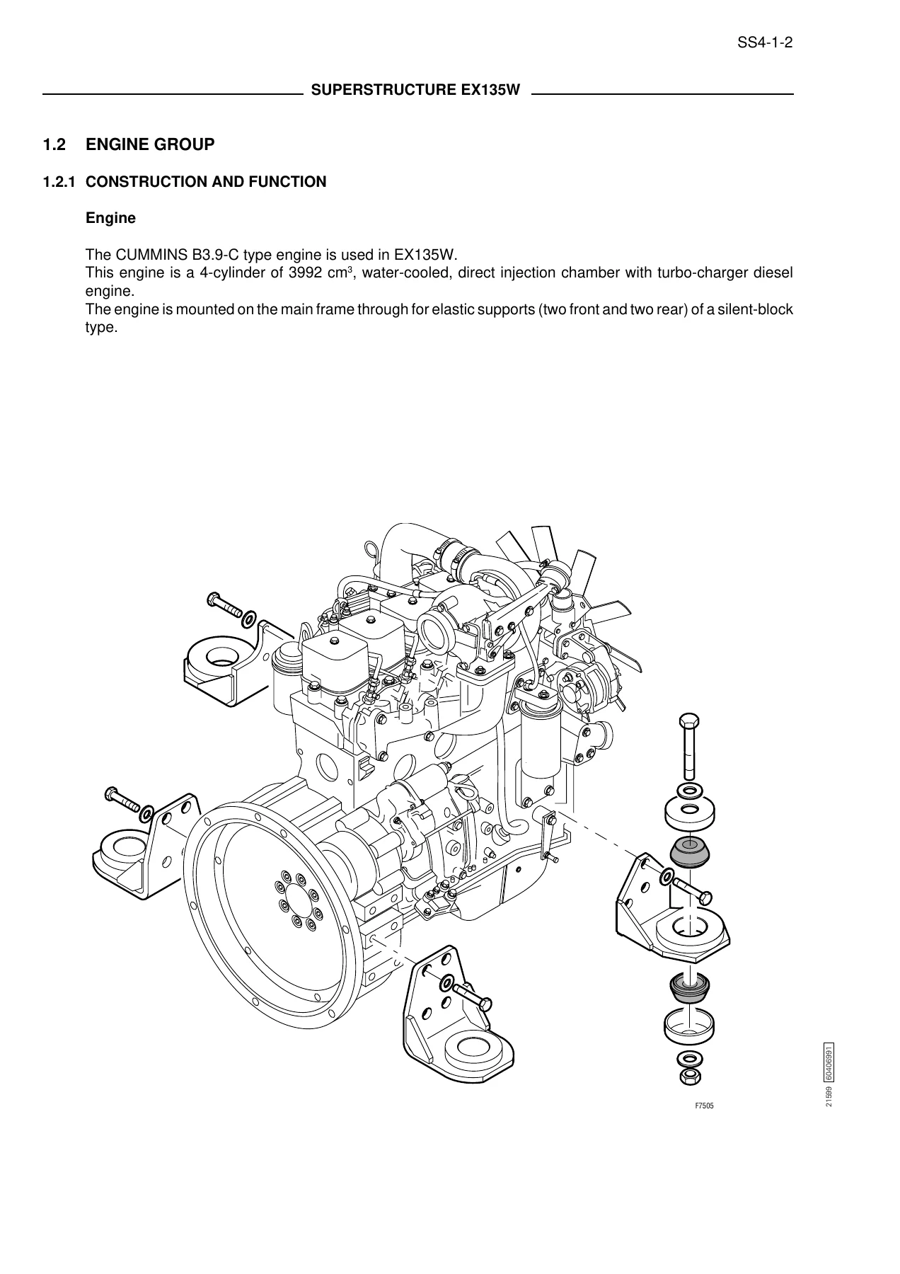
In the superstructure section, technicians will find detailed information on the main frame and counterweight construction, engine group components including the air cleaner and exhaust silencer, hydraulic oil reservoir with full-flow and suction filters, fuel reservoir, various covers and protections, cab group with operator’s seat and controls, cab heater, and cab and chassis electric components. The hydraulic pumps section provides both operation principle and disassembly/assembly procedures for the main pump, secondary pump, and gear double pump, including detailed regulator and rotor group explanations.
The EX135W service manual also includes comprehensive coverage of the control valve, with operation principle and disassembly/assembly procedures for the right body, central body, and left body, covering directional control valves, pressure relief valves, anticavitation valves, cut-off valves, flow limiter valves, drain pressurisation valves, and pressure compensators. The swing device section covers the swing hydraulic motor, swing reduction device, and swing relief valves in full detail.
The undercarriage section addresses the lower frame, swing bearing, travel unit, wheels (including twin and individual tyre assembly procedures), blade assembly, lateral stabilizers, and hydraulic hoses. The travel hydraulic motor, transmission, axles, and transmission shaft are each covered with operation principle and disassembly/assembly instructions. The front-end attachment section covers boom, arm, and bucket assemblies, front pipings, maintenance standards, hydraulic cylinders, and pins and bushings, with detailed specifications for both monobloc and triple articulation versions.
The hydraulic system section is particularly extensive, covering the main hydraulic system with suction, delivery, return, and drainage circuits; the pilot/brakes system; the steering system; the brakes system with brake pedal valve operation; the operation of circuits for boom, dipper stick, bucket, positioner arm, travel, blade, side stabilisers, and turret swing; the travel circuit with travel hydraulic motor control, transmission control, and parking brake control; and a complete hydraulic system diagram.
The electrical system section provides safety rules, specifications and data, location and functions of components, arrangements and operation, electronic control units and diodes (including the APC50 electronic unit and SMC throttle piston control unit), electric components, and control line and wiring harnesses. The troubleshooting section offers structured diagnostic procedures for the hydraulic system (including front attachment, swing, travel, brake system, steering system, drive axles, and transmission) and the electrical system (including electrical system components, relays and fuses, checks on electrical components, pilot electronical circuit checks, brake system electrical circuit checks, travel control electrical circuits checks, stabilizers control electrical circuits checks, blade control, positioning control, hammer control, axle lock, monitor, throttle control, diesel engine starting, and transmission control electronic unit checks).
IMAGES PREVIEW
The operational performance test section provides a table of excavator performance standards, hydraulic components performance standards, main pump and secondary pump P-Q diagrams, preparation for performance testing, and detailed procedures for testing engine performance, swing performance, front attachment performance, control lever performance, lift/swing performance, steering, brakes system, and transmission, along with component performance tests for pilot pressure relief valve, pressure relief valves, flow control priority valve, transmission drive shaft, and hydraulic pumps.
Who This Manual Is For
This Fiat-Hitachi EX135W repair manual is written for skilled technicians, mechanics, and service personnel who need to repair, maintain, or overhaul the EX135W excavator. It assumes a professional level of technical knowledge and is designed to provide the information necessary to perform accurate repairs. The manual is equally valuable for training new personnel who will be employed in machine maintenance, as the information is presented in a systematic and rational manner that reduces repair errors and delays.
Owners and operators of the Fiat-Hitachi EX135W will also find this manual invaluable for understanding the machine’s systems, performing routine maintenance correctly, and diagnosing problems before they escalate. The troubleshooting and performance test sections make it possible to systematically identify issues and verify repairs, ensuring the machine operates within factory specifications.
Get Your Fiat-Hitachi EX135W Workshop Manual Today
This Fiat-Hitachi EX135W Excavator Workshop Manual 604.06.991 gives you the capability to perform everything from routine maintenance to complete component overhauls. With approximately 996 pages of detailed procedures, technical specifications, exploded illustrations, hydraulic and electrical diagrams, and diagnostic troubleshooting guides, this manual is the most comprehensive resource available for the EX135W machine. Whether you are rebuilding a hydraulic pump, diagnosing an electrical fault, adjusting brake pressures, or verifying engine performance, having the correct procedures and specifications at hand is essential to doing the job right the first time.
Delivered as an instant PDF download after payment, this manual requires no shipping and can be accessed immediately on any device – desktop, laptop, tablet, or smartphone. Print the pages you need for the workshop, or keep the entire manual on your computer for quick reference. The PDF format allows you to view, search, and print the complete document as needed.
Don’t rely on guesswork or incomplete information when servicing your Fiat-Hitachi EX135W. Get the complete workshop manual and work with confidence.
Reviews
There are no reviews yet.