
John Deere 210G 210GLC Excavator Repair Technical Manual TM12333 Download
Original price was: $44.95.$26.95Current price is: $26.95.
Complete John Deere 210G and 210GLC Excavator Repair Technical Manual TM12333 covering undercarriage, hydraulics, engine removal, swing system, torque values and dealer fabricated tools. Instant PDF download.
Description
John Deere 210G and 210GLC Excavator Repair Technical Manual TM12333
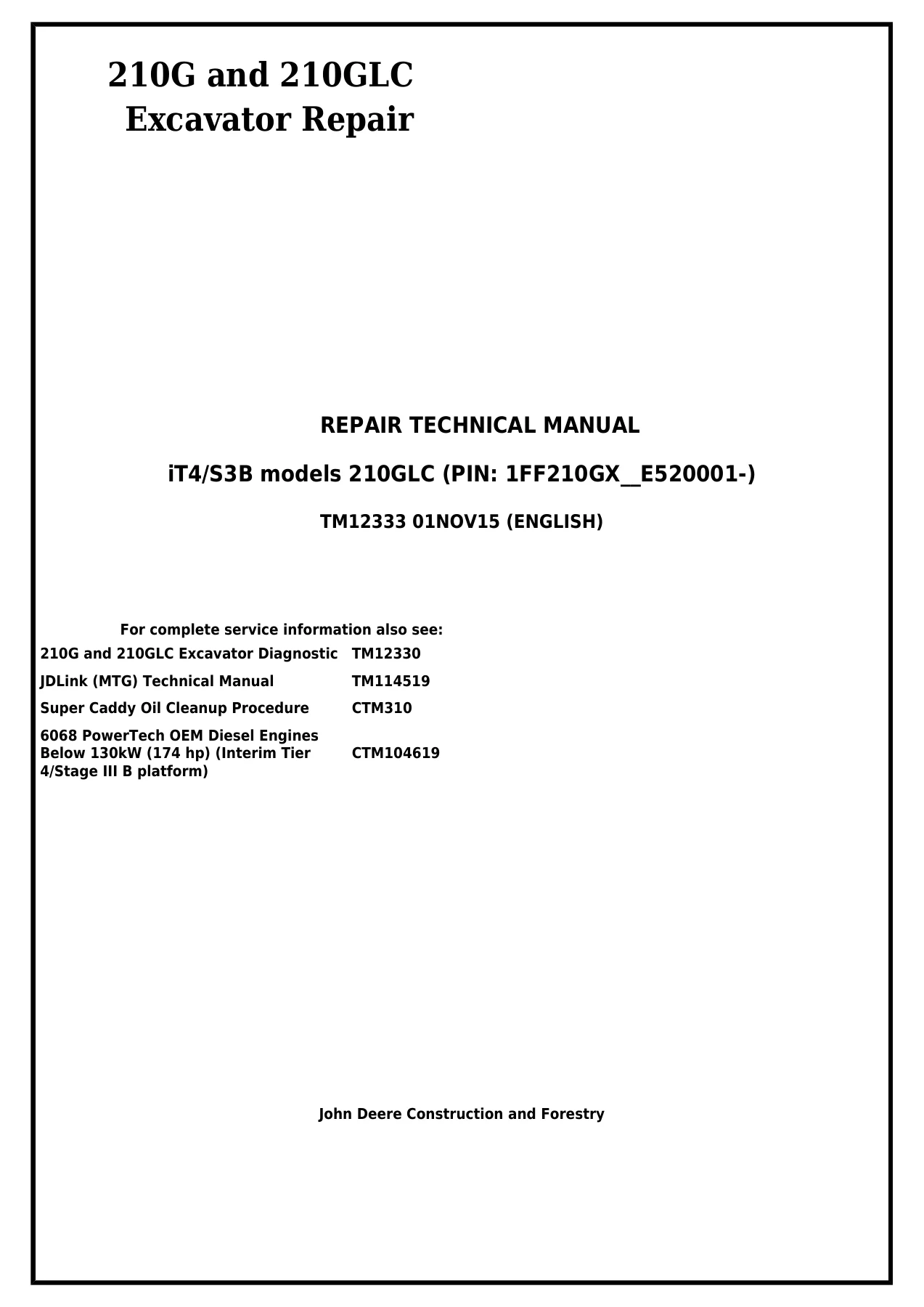
This is the complete John Deere 210G and 210GLC Excavator Repair Technical Manual, publication TM12333, issued 01NOV15 for iT4/S3B machines. It is the working document a technician reaches for when a 210G or 210GLC needs more than a filter change, covering everything from a single track roller replacement through to a full engine removal and a travel gear case split. Every group opens with its own summary listing of the essential tools, service equipment, required materials, service parts kits, specifications, wear tolerances and torque values that apply to that job, so the correct numbers are in front of you before the first fastener is loosened.
File Details
- Manual type: Repair Technical Manual
- Brand: John Deere
- Models covered: 210G and 210GLC Excavator
- Publication number: TM12333
- Edition date: 01NOV15
- Language: English
- Page count: 594 pages
- File format: PDF
- Model configuration: iT4/S3B models 210GLC (PIN: 1FF210GX_E520001-)
- Companion publications referenced: TM12330 Diagnostic, TM114519 JDLink (MTG), CTM310 Super Caddy Oil Cleanup, CTM104619 6068 PowerTech OEM Diesel Engines Below 130 kW (174 hp)
Chapters Covered
- Section 00 – General Information: Group 0001 Safety, Group 0003 Torque Values
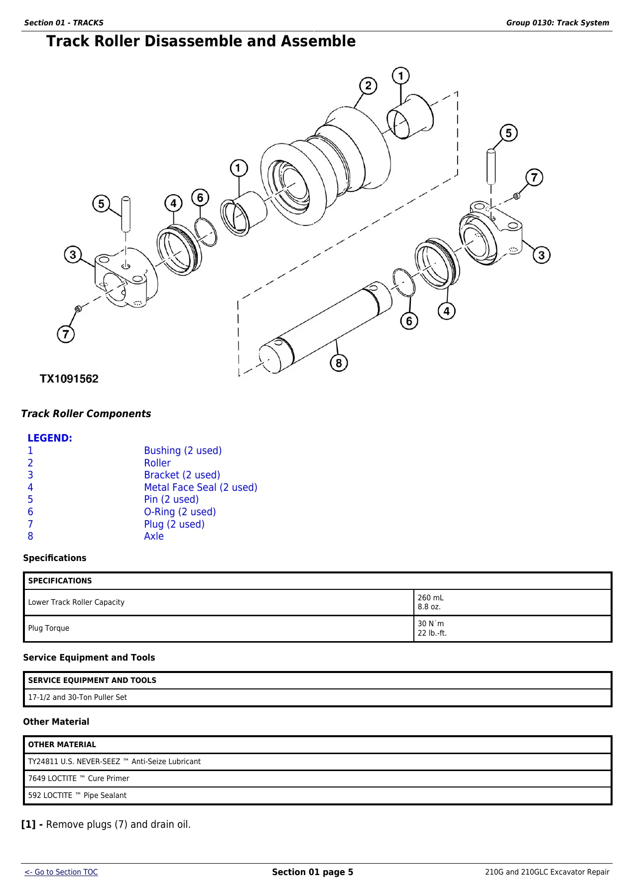
- Section 01 – Tracks: Group 0130 Track System
- Section 02 – Axles, Differentials and Suspension Systems: Group 0250 Axle Shaft, Bearings and Reduction Gears; Group 0260 Hydraulic System
- Section 04 – Engine: Group 0400 Removal and Installation
- Section 05 – Engine Auxiliary System: Group 0510 Cooling Systems, Group 0520 Intake System, Group 0530 External Exhaust System, Group 0560 External Fuel Supply Systems
- Section 07 – Damper Drive (Flex Coupling): Group 0752 Elements
- Section 17 – Frame or Supporting Structure: Group 1740 Frame Installation, Group 1749 Chassis Weights
- Section 18 – Operator’s Station: Group 1800 Removal and Installation, Group 1810 Operator Enclosure, Group 1821 Seat and Seat Belt, Group 1830 Heating and Air Conditioning
- Section 19 – Sheet Metal: Group 1910 Hood and Engine Side Shield
- Section 33 – Excavator: Group 3302 Buckets, Group 3340 Frames, Group 3360 Hydraulic System
- Section 43 – Swing or Pivoting System: Group 4350 Mechanical Drive Elements, Group 4360 Hydraulic Systems
- Section 99 – Dealer Fabricated Tools: Group 9900 Dealer Fabricated Tools
Read together, those twelve sections form a single continuous repair path across the whole machine. The undercarriage section alone walks through track roller removal, disassembly, pressure testing and metal face seal inspection, track shoe and track chain removal, track chain disassembly and reassembly, broken track pin and track link repair, sprocket and front idler service, and the track adjuster and recoil spring job including the compression tooling. Section 33 then takes the front attachment apart joint by joint – bucket, bucket links, arm, boom, pins, bushings, bosses and the hydraulic cylinders at the boom, arm and bucket positions – with the pin and bushing wear limits printed alongside. Section 43 handles the upperstructure, swing bearing, swing gear case, center joint, swing motor and park brake as separate, fully detailed procedures with their own disassembly and assembly sequences.
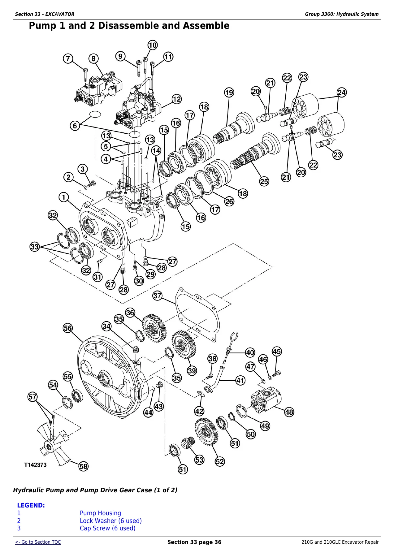
For the John Deere 210G and 210GLC Excavator Repair Technical Manual, the hydraulic content is where most of the working hours live. Pump 1 and 2 removal and installation, disassembly and assembly, inspection and start-up procedure are all covered, along with the pump regulators, the pilot pump, the pilot pressure regulating valve and filter, the pilot shutoff solenoid valve, the fan drive pump and motor, the solenoid valve manifolds and the 4-spool and 5-spool control valve halves. The hydraulic oil tank, restriction valve, oil cooler bypass valve and all three main cylinders each get a dedicated remove and install plus a separate disassemble and assemble procedure, with piston nut torque values and rod curvature limits given for each.
Coverage Depth for the 210G and 210GLC
This is not a condensed or abridged guide. Removal and installation procedures are written as full step sequences with component weights quoted so the right lifting equipment is selected before anything is unbolted – the counterweight at approximately 4250 kg, the cab at 658 kg, the upperstructure at 5962 kg, the swing bearing at 324 kg, and the pump drive gear case with pump 1 and 2 at 196 kg are all stated. Torque values are carried through to the individual fastener: cab mount cap screws, swing bearing-to-upperstructure cap screws, counterweight cap screws, sprocket-to-travel gear case cap screws, track shoe-to-link initial and final torque, boom foot pin cap screw, boom and arm cylinder piston nuts, and the cylinder head-to-barrel cap screws on every cylinder. Capacity data appears where it is needed as well, including the fuel tank at 403 L, the hydraulic oil tank at 135.0 L, the swing gear case at 6.2 L, the coolant system at 30.5 L and the front idler oil at 265 mL.
The General Information section is not filler. It carries the safety content used throughout the rest of the manual – high-pressure fluid hazards, ROPS handling, supported machine preparation, cooling system safety, welding precautions, exhaust filter ash handling and decommissioning – followed by the full metric and unified inch bolt and cap screw torque tables, the straight fitting and special nut torque charts, O-ring boss and O-ring face seal fitting torque values for both standard and high pressure service, four bolt flange fitting torque charts, and the metric 24 degree O-ring seal DIN 20078 recommendations. The final section reproduces the dealer fabricated tool drawings for the lift brackets, the track recoil spring disassembly and assembly tool and its guard, the travel gear case nut wrench and holding bar, the center joint lifting tool, the pump support and the swing gear case nut spanner wrench, so the special tooling can be made rather than sourced.
Why This Manual Matters in the Shop
Buyers running a John Deere 210G or 210GLC Excavator know that guessing at a torque value or reusing a worn metal face seal is how a repair turns into a repeat repair. This Repair Technical Manual TM12333 gives the wear tolerances, the clearances, the limits of use and the tightening sequences that separate a correct rebuild from an expensive experiment – swing bearing installation positioning, boom thrust plate clearance, arm thrust plate clearance, bucket pivot end play, pump drive and driven gear backlash, and the piston-to-bore clearances inside the hydraulic pumps. Diagnostics on the hydraulic and electrical side are cross-referenced to the companion TM12330 Diagnostic manual, and the alternator, starter, harness connectors, sensors, solenoids and pressure switches are all identified by their component codes so they can be found quickly on the machine.
IMAGES PREVIEW
The moment payment clears, the John Deere 210G and 210GLC Excavator Repair Technical Manual TM12333 is delivered as an instant PDF download – no shipping, no waiting, no lost paper copy. Open it on a laptop in the service truck, a tablet on the machine deck or a phone in the pit, print only the group you are working on, and keep the rest of the manual clean. For a 210G or 210GLC that is going to stay in the fleet, this is the reference that keeps the undercarriage, the hydraulics, the swing system and the engine work moving in the right order.

Reviews
There are no reviews yet.