
FPT Cursor C87 ENT X Cursor 87 TE X Tier 3 Technical and Repair Manual – PDF
Original price was: $39.95.$24.95Current price is: $24.95.
Complete FPT Cursor C87 ENT X and Cursor 87 TE X Tier 3 industrial engine technical and repair manual. Covers F2C Cursor engines, G-Drive applications, overhaul procedures, specifications, electrical systems, troubleshooting, and maintenance. Publication P2D32C006E.
Description
FPT Cursor C87 ENT X Cursor 87 TE X Tier 3 Technical and Repair Manual
This Technical and Repair Manual covers the FPT (Fiat Powertrain Technologies) Cursor Tier 3 Series industrial engines, specifically the C87 ENT X and Cursor 87 TE X models. It is the complete service documentation for the F2C Cursor engine family, covering both the industrial application and the G-Drive configuration. Publication number P2D32C006E, 2nd Edition, dated 06.2007.
Whether you are performing routine maintenance, diagnosing a fault, or undertaking a full engine overhaul on a Cursor C87 ENT X or Cursor 87 TE X, this manual provides the specifications, tightening torques, procedures, and technical data required to complete the work correctly.
File Details
- Manual Type: Technical and Repair Manual (Service Manual)
- Brand: FPT (Fiat Powertrain Technologies)
- Models Covered: C87 ENT X, Cursor 87 TE X, Cursor C87
- Engine Family: F2C Cursor Tier 3 Series
- Language: English
- Publication Number: P2D32C006E
- Edition: 2nd Edition
- Date: 06.2007
- File Format: PDF
Chapters Covered
- General Specifications
- Mapping Between Technical and Commercial Coding
- Views of the Engine
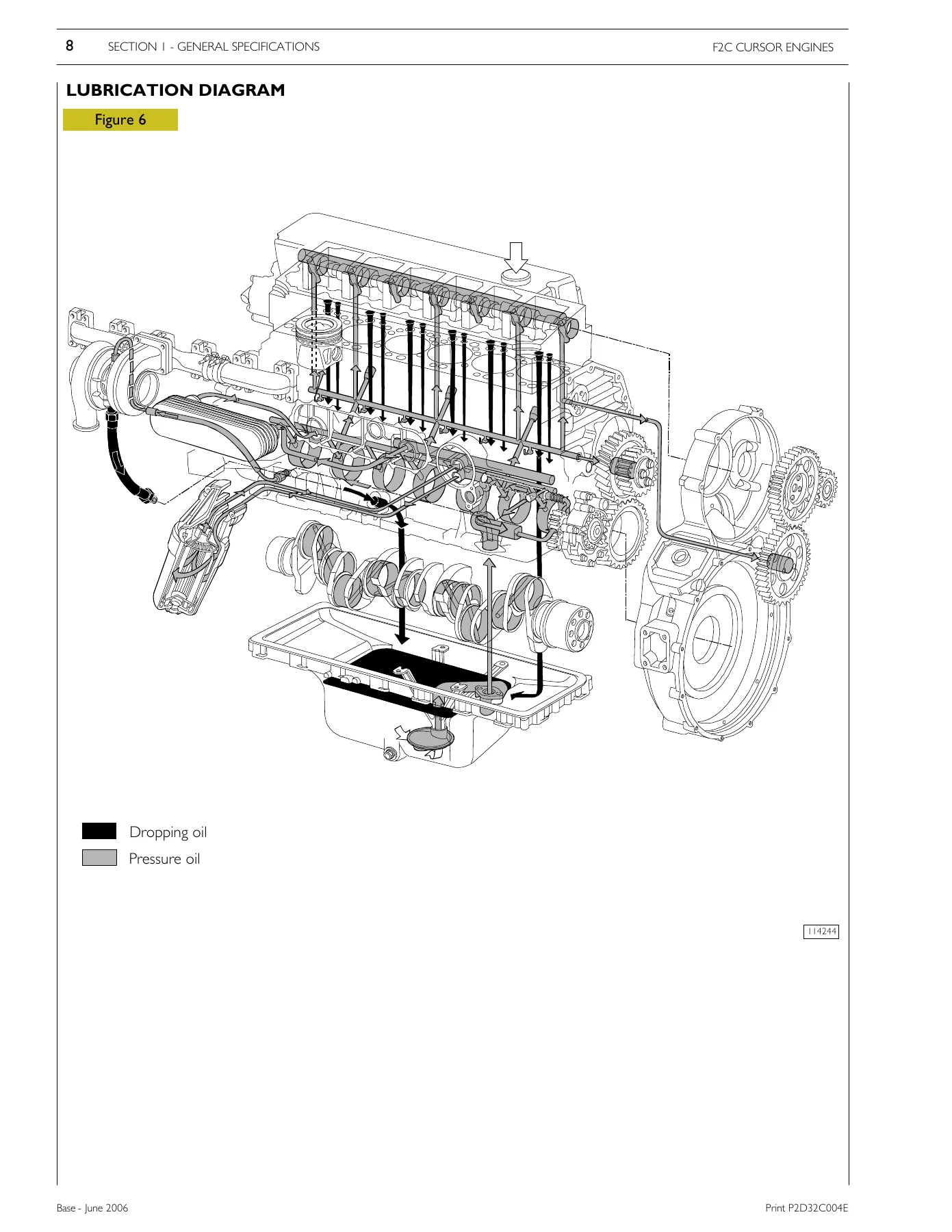
- Lubrication Diagram
- Oil Pump
- Overpressure Valve
- Oil Pressure Control Valve
- Heat Exchanger
- Engine Oil Filter – Characteristics, Lock Torques, Installation Rule, Filter By-Pass Valve
- Replacing Oil Filter Cartridge – Dismantling, Refitting
- Oil Fume Recycle (Blow-by)
- Cooling – Description, Operation, Water Pump, Thermostat
- Turbocharging
- EGR Exhaust Gas Recycle System
- Internal EGR Operating on Suction Valves
- Fuel
- Supply
- Fuel Supply Diagram
- Mechanical Supply Pump – Normal Operating Conditions, Overpressure Condition at Outlet, Drain Conditions
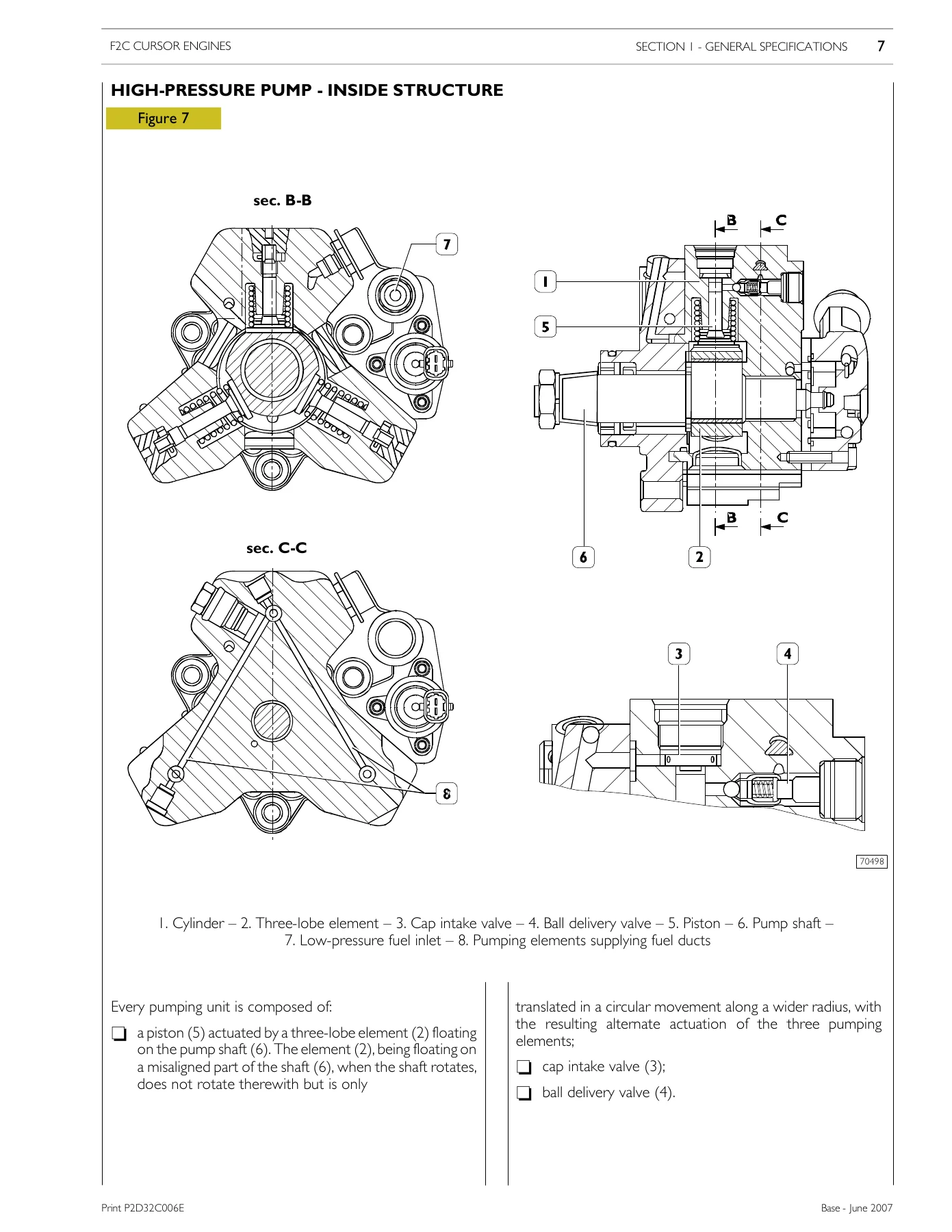
- CP3 High-Pressure Pump
- High-Pressure Pump – Inside Structure
- Operating Principle
- Operation
- Rail (Pressure Accumulator)
- Electroinjector
- Industrial Application
- Clearance Data
- Part One – Mechanical Components: Engine Disassembly on Bench, Assembly, High Pressure Pump Installation, Engine Flywheel, Engine Flywheel Installation, Camshaft Installation, Timing Camshaft and Flywheel (With and Without Tool 99395223), Intake and Exhaust Rocker Arm Clearance Adjustment, Engine Assembly Completion
- Part Two – Electrical Equipment: Components on the Engine F2C, Engine Cable, EDC 7 UC31 Control Unit Pin-Out, EDC Control Unit PIN-OUT, Electroinjectors, Engine Coolant Temperature Sensor, Fuel Temperature Sensor, High Pressure Pump (Pressure Regulator), Flywheel Pulse Transmitter, Distribution Pulse Transmitter, Fuel Pressure Sensor on Rail, Alternator, Starting Motor, EDC System Functions
- Part Three – Troubleshooting: Methods of Diagnosis, PT-01 Portable Tester, Main Functions, Test Parameters, Preface, Fault Codes
- Part Four – Maintenance Planning: Maintenance Services Chart, Checks and/or Maintenance Work, Off-Plane Operations
- Overhaul and Technical Specifications
- General Characteristics
- Assembly Clearance Data
- Engine Overhaul – Engine Removal at the Bench
- Repair Operations
- Cylinder Block – Checks and Measurements
- Cylinder Liners – Replacing Cylinder Liners, Removal, Fitting and Checking Protrusion
- Crankshaft – Measuring Main Journals and Crank Pins
- Preliminary Measurement of Main and Big End Bearing Shell Selection Data
- Selecting the Main and Big End Bearing Shells
- Replacing the Timing Control Gear and the Oil Pump
- Checking Main Journal Installation Clearance
- Checking Crankshaft End Float
- Piston-Connecting Rod Assembly – Removal, Measuring the Diameter of the Pistons, Conditions for Correct Gudgeon Pin-Piston Coupling, Piston Rings
- Connecting Rod – Checking Connecting Rod Alignment, Mounting the Connecting Rod-Piston Assembly, Mounting the Piston Rings, Fitting the Connecting Rod-Piston Assembly into the Piston Liners, Piston Protrusion Check, Checking Assembly Clearance of Big End Pins
- Cylinder Head – Dismounting the Valves, Checking the Planarity of the Head on the Cylinder Block
- Valve – Removing Deposits and Checking the Valves
- Valve Guides – Replacing of Valve Guides, Replacing – Reaming the Valve Seats
- Replacing Injector Holder Cases – Removal, Checking Protrusion of Injectors
- Timing Gear – Camshaft Drive, Intermediate Gear Pin, Idler Gear, Twin Idler Gear, Replacing the Bushings, Camshaft, Checking Cam Lift and Pin Alignment, Bushes, Use Beater 99360505 to Change Bushings, Removal, Fitting
- Valve Springs – Fitting the Valves and Oil Seal Ring
- Rocker Shaft – Shaft, Rocker
- Tightening Torques
- Tools
- Tools
- Equipment Modified for Adaptation to Cursor
- Engine
- Part 2 – G-Drive Cursor Engines
- General Specifications
- Correspondence Between Technical Code and Commercial Code
- Lubrication
- Cooling – Description, Operation
- Fuel Feed
- Turbocharging
- G-Drive Application – F3B General Characteristics, F3B Assembly Clearance Data
- Engine Connection and Disconnection from the Radiator – Removal, Refitting
- Maintenance Planning – Recovery, Inspection and/or Maintenance Interventions, Operations Outside the Plan, Daily Checks, Every Year – Before Winter, Every Two Year
- Maintenance Procedures – Checks and Controls
- Principle Electrical Diagram
- Key to Components
- Function Symbols for the Control Panel
- Engine Interface Box – Description, Connectors
- EDC 7 UC31 Electronic Control Unit
- EDC Control Unit PIN-OUT
- Appendix – Safety Prescriptions
- Standard Safety Prescriptions
- Prevention of Injury
- During Maintenance
- Respect of the Environment
The scope of this FPT Cursor C87 ENT X and Cursor 87 TE X technical and repair manual is comprehensive. It moves from general engine specifications and system descriptions through to full disassembly, inspection, measurement, and reassembly of the F2C Cursor engine. The industrial application section covers the engine as installed in machinery, while the dedicated G-Drive section addresses the specific configuration used in generator drive applications, including the radiator connection and the engine interface box. The electrical section provides EDC 7 UC31 control unit pin-outs, sensor data, and wiring information. The troubleshooting chapter includes fault codes and diagnostic methods using the PT-01 portable tester. The overhaul section gives the clearances, wear limits, and tightening torques needed to rebuild the engine to specification.
What This Manual Enables You to Do
With this manual, a qualified technician can carry out the full range of service and repair operations on the FPT Cursor C87 ENT X and Cursor 87 TE X engines. That includes:
- Diagnose faults using the EDC 7 UC31 fault codes and the PT-01 portable tester.
- Remove and refit the engine from the machine or G-Drive package.
- Overhaul the cylinder head, including valve removal, valve guide replacement, and valve seat reaming.
- Remove and refit cylinder liners, checking protrusion and selecting the correct adjustment ring.
- Measure and assess the crankshaft, main journals, and crank pins, and select the correct bearing shells.
- Disassemble and reassemble the piston and connecting rod assembly, including piston ring fitting and checking piston protrusion.
- Set the engine timing using the specified tools and procedures, both with and without tool 99395223.
- Replace the high-pressure fuel pump, pressure regulator, and injectors, and check injector protrusion.
- Service the cooling system, including the water pump and thermostat.
- Service the lubrication system, including the oil pump, heat exchanger, and oil filter.
- Carry out maintenance according to the schedule, including oil changes, filter changes, and valve clearance adjustment.
- Understand and troubleshoot the EGR system and turbocharging system.
The value of having the correct procedures and specifications cannot be overstated. The F2C Cursor engine uses a Common Rail fuel system with high-pressure pump CP3.3 and CRIN2 injectors. The tightening torques, assembly clearances, and selection data for bearing shells and pistons are critical to reliable operation and longevity. Using incorrect values can lead to premature failure, poor performance, or damage to the engine. This manual provides the data directly from FPT.
IMAGES PREVIEW
Instant PDF Delivery
The manual is delivered as a PDF file. There is no shipping and no waiting for a physical book. Once payment is complete, you can download it immediately and access it on any device, including laptops, tablets, and smartphones. You can print the pages you need for the workshop and keep the full manual for reference. This makes it practical for both workshop use and on-site repairs.


Reviews
There are no reviews yet.