★ TRUSTED BY 321,897+ PROFESSIONALS WORLDWIDE
🏢
Trusted Business
Verified & Licensed
🛡️
Virus Free Files
100% Safe Downloads
🔒
Secure Payment
SSL Protected
Instant Delivery
Available Immediately
Sale!

Doosan DX300LCA Excavator Shop Manual 950106-00075E – 2010 PDF Repair Guide

Original price was: $39.95.Current price is: $24.95.

Complete 2010 Doosan DX300LCA Track Excavator Shop Manual in PDF. Covers serial 5001 and up with full service, repair, hydraulic, electrical, and maintenance procedures. Document 950106-00075E.

Instant PDF Download
Available immediately
💾
Save to Your Device
Download & keep forever
🛡️
Antivirus Scanned
100% virus-free
🌍
Trusted Worldwide
175,000+ customers

Description

Doosan DX300LCA Excavator Shop Manual — Complete Repair & Service Guide

This Doosan DX300LCA Excavator Shop Manual is a comprehensive PDF service and repair guide covering serial number 5001 and up. Published under document number 950106-00075E in 2010, this workshop manual gives technicians, mechanics, and equipment owners the detailed procedures, specifications, and diagnostic information needed to maintain and repair the DX300LCA track excavator.

File Details

  • Manual Type: Shop Manual (Service & Repair)
  • Brand: DOOSAN
  • Primary Model: DX300LCA
  • Serial Number Range: 5001 and Up
  • Document Number: 950106-00075E
  • Year: 2010
  • Language: English
  • File Format: PDF
  • Page Count: 810 pages

IMAGES PREVIEW

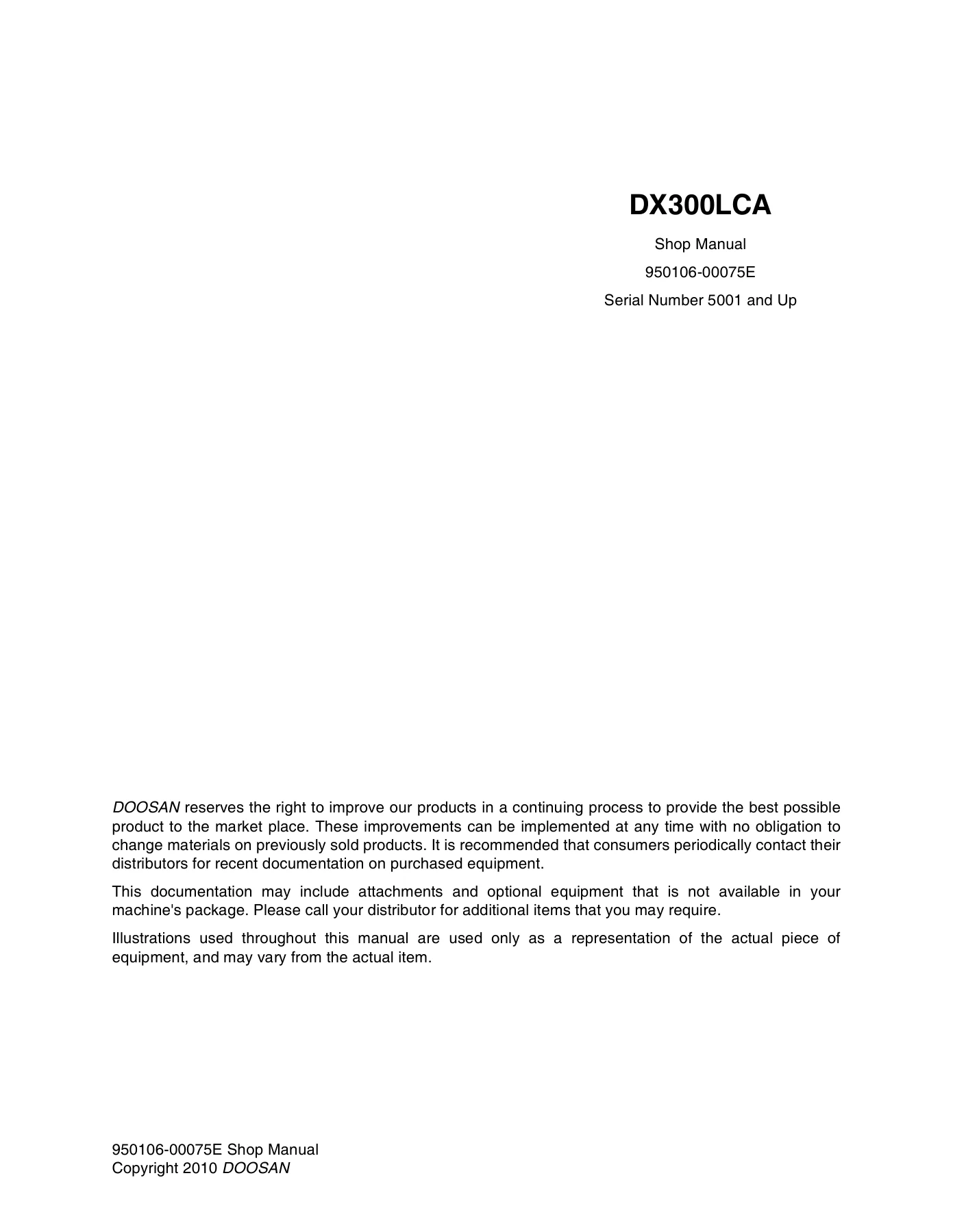
Doosan DX300LCA Excavator Shop Manual 950106-00075E - 2010 PDF Repair Guide — PDF page 1 preview
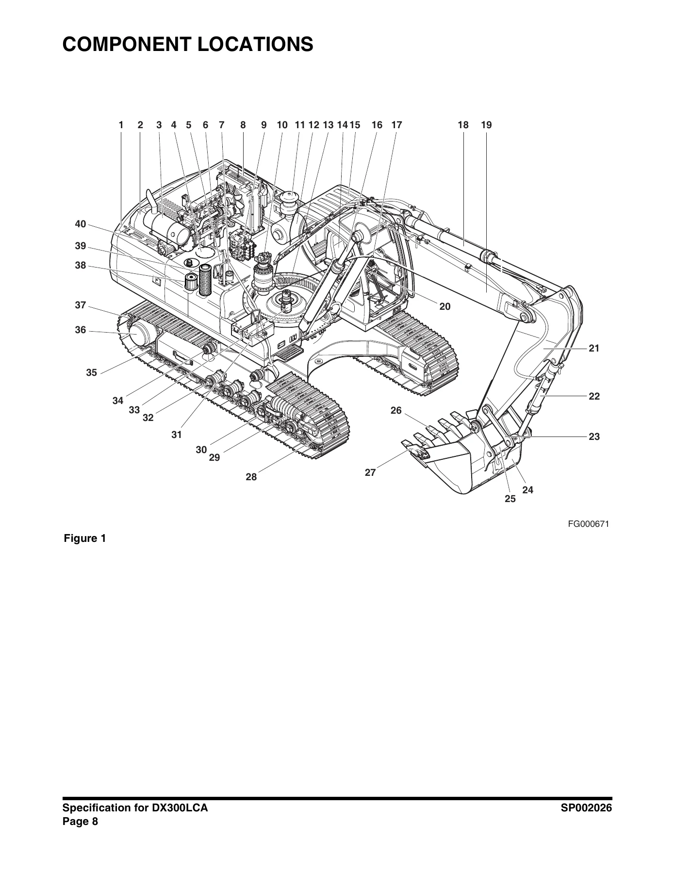
Doosan DX300LCA Excavator Shop Manual 950106-00075E - 2010 PDF Repair Guide — PDF page 60 preview
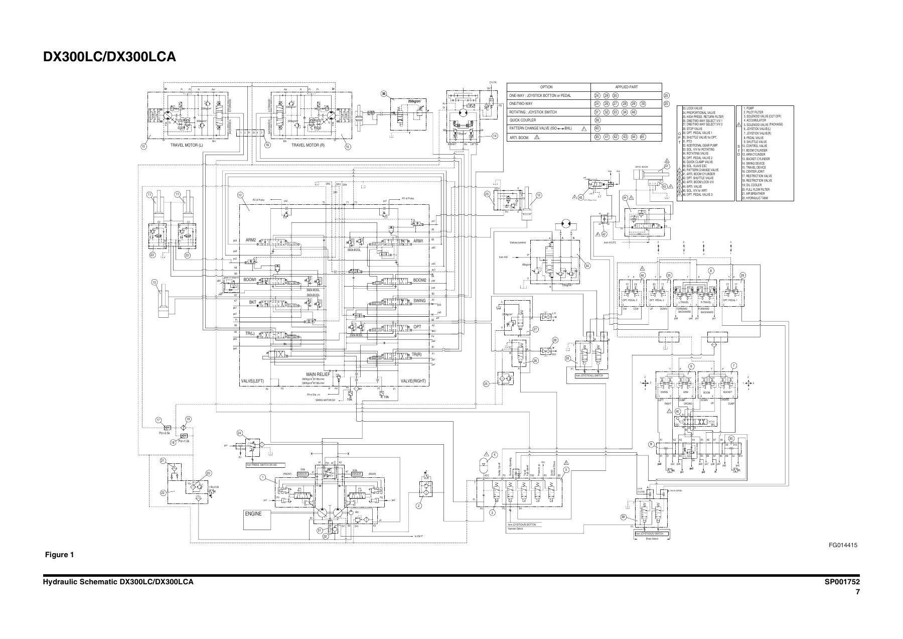
Doosan DX300LCA Excavator Shop Manual 950106-00075E - 2010 PDF Repair Guide — PDF page 655 preview

Chapters Covered

  • Safety — Track Excavator Safety (SP002025): safety precautions, applicable models, general safety essentials, location of safety labels, lifting precautions, unauthorized modifications, general hazard information, before starting engine, machine operation, maintenance, battery, towing, shipping and transportation, lifting with sling.
  • Specifications — Specification for DX300LCA (SP002026): general description, component locations, general dimensions, working range, general specifications, engine performance curves, approximate weight of workload materials, performance tests, excavator performance standards, travel speed and travel motor balance tests, swing speed and deceleration force test, cylinder performance tests.
  • General Maintenance — General Maintenance Procedures (SP000016), Standard Torques (SP000813): hydraulic system general precautions, maintenance service and repair procedure, hydraulic system cleanliness and oil leaks, bearing inspection, torque values for standard metric and U.S. fasteners, type 8 phosphate coated hardware, torque values for hose clamps and split flanges, torque wrench extension tools.
  • Upper Structure — Cabin (SP001737), Counterweight (SP001748), Fuel Tank (SP002027), Fuel Transfer Pump (SP000021), Swing Bearing (SP001856), Swing Reduction Gear (SP002028): removal and installation procedures, disassembly and reassembly, cleaning and inspection, wear limits and tolerances, start-up procedures.
  • Lower Structure and Chassis — Track Assembly (SP001741): track tension, cleaning and inspection, wear limits and tolerances for track shoe, lower roller, upper roller, front idler, track shoes and links, track removal and installation, front idler roller, lower roller, upper roller, track spring and track adjusting cylinder.
  • Engine and Drive Train — Drive Coupling / Main Pump (SP002029): drive coupling installation, special tools, installation procedure.
  • Hydraulics — Hydraulic System Troubleshooting, Testing and Adjustment (SP001751), Accumulator (SP000028), Center Joint / Swivel (SP001620), Cylinders (SP000030), Swing Motor (SP000031), Travel Motor (SP000032), Travel Reduction Gear (SP000071), Axial Piston Pump (SP000068), Gear Pump (SP000033), Main Control Valve (SP000034), Remote Control Valve / Joystick (SP000069), Travel Control Valve with Damper (SP001743), Solenoid Valve Assembly (SP001622), Breaker EPPR Valve (SP000192), Hydraulic Schematic DX300LC/DX300LCA (SP001752): operation of working components, procedural troubleshooting, pilot pressure adjustment and testing, power mode valve adjustments, pressure up valve checks, pump input power control, flow meter installation and testing, swing system troubleshooting, control valve troubleshooting, travel control valve, joystick control valve, relief valve maintenance, start-up procedures.
  • Electrical System — Electrical System (SP002030), Electrical Schematic DX300LCA (SP002031): electrical supply system, engine starting circuit, engine preheating system, engine stop, charging system, monitoring system, warning and indicator lights, mode selector switch, graphic information area display, main menu, special menu, electronic hydraulic control system (e-EPOS), power mode control, engine control system, engine control motor, engine control dial, automatic deceleration control, engine overheat protection system, power boost mode, automatic travel speed control, self-diagnostic function, air conditioner system, troubleshooting, wiper system, lighting system, overload warning device, audio controller.
  • Attachments — Boom and Arm (SP001851), Bucket (SP001852): front attachment pin specifications, removal and installation procedures, start-up procedures, bucket tooth inspection and replacement, bucket O-ring replacement, bucket shimming procedures, bucket attachment, removal and reversal.

This Doosan DX300LCA shop manual is not a generic overview — it is a full workshop-level document that walks through every major system on the machine. The hydraulics section alone covers the main control valve, swing motor, travel motor, axial piston pump, gear pump, cylinders, center joint, accumulator, remote control valve, travel control valve, solenoid valve assembly, and breaker EPPR valve with complete disassembly, inspection, and reassembly steps. The electrical section includes the full e-EPOS electronic control system, engine control circuits, monitoring system, air conditioner diagnostics, and wiper and lighting circuits. The upper structure and lower structure sections provide step-by-step removal and installation for the cabin, counterweight, fuel tank, swing bearing, swing reduction gear, and complete track assembly including rollers, idlers, and track tension adjustment. The specification section gives general dimensions, working range diagrams, engine performance curves, hydraulic pressures, actuator speeds, torque values, and wear limits that a technician needs to make accurate adjustments and determine whether components are within serviceable tolerances.

Complete PDF Bookmark Tree

Complete Bookmarks

The complete bookmarks in the “Doosan DX300LCA Excavator Shop Manual 950106-00075E – 2010 PDF Repair Guide” are as follows:

DX300LCAp. 1
Table of Contentsp. 5
Safetyp. 7
Track Excavator Safetyp. 9
Safety Precautionsp. 13
Applicable Modelsp. 13
To the Operator of a DOOSAN Excavatorp. 14
Learn the Signal Words Used with the Safety Alert Symbolp. 16
General Safety Essentialsp. 17
Accessory Applicationsp. 17
Lifting Capacity Rating Configurationp. 17
Location of Safety Labelsp. 18
Summary of Safety Precautions for Lifting in Digging Modep. 18
Unauthorized Modificationsp. 19
General Hazard Informationp. 19
Safety Rulesp. 19
Safety Featuresp. 20
Inside Operator's Cabinp. 20
Clothing and Personal Protective Itemsp. 21
Breathing Masks, Ear Protection May Be Requiredp. 21
Vibration Level Informationp. 21
Recommendations for Limiting Vibrationsp. 22
Mounting and Dismountingp. 23
Fuel, Oil and Hydraulic Fluid Fire Hazardsp. 23
Precautions When Handling Fluids at High Temperaturep. 24
Asbestos Dust Hazard Preventionp. 24
Injury from Work Equipmentp. 25
Fire Extinguisher and First Aid Kitp. 25
Protection from Falling or Flying Objectsp. 26
Attachment Precautionsp. 26
Accumulatorp. 27
Indoor Ventilationp. 27
Emergency Exitp. 27
Before Starting Enginep. 28
Work Site Precautionsp. 28
Checks Before Starting Enginep. 29
Engine Startingp. 30
Before Operating Machinep. 31
Machine Operationp. 32
When Swinging or Changing Direction of Travelp. 32
Travel Precautionsp. 33
Traveling on Slopesp. 34
Prohibited Operationsp. 35
Precautions for Operationp. 36
Avoid High-Voltage Cablesp. 36
Protecting Cabin from Falling Object (Optional)p. 37
Operate Carefully on Snow, Ice and in Very Cold Temperaturesp. 37
Operations on Slopesp. 38
Parking Machinep. 38
Never Let Anyone Ride on Attachmentp. 38
Maintenancep. 39
Warning Tagp. 39
Clean Before Inspection or Maintenancep. 39
Proper Toolsp. 40
Use of Lightingp. 40
Fire Prevention and Explosion Preventionp. 40
Burn Preventionp. 41
Welding Repairsp. 42
Warning for Counterweight and Front Attachment Removalp. 42
Precautions for Removal, Installation, and Storage of Attachmentsp. 43
Precautions When Working on Machinep. 43
Lock Inspection Coversp. 43
Prevention of Crushing and Cuttingp. 44
Track Tension Adjustments Require Cautionp. 44
Supports and Blocking for Work Equipmentp. 44
Action When Abnormality Is Found During Inspectionp. 45
Precautions with High-pressure Lines, Tubes and Hosesp. 45
Waste Materialsp. 46
Batteryp. 47
Battery Hazard Preventionp. 47
Boost Starting or Charging Engine Batteriesp. 48
Towingp. 49
Precautions When Towingp. 49
Shipping and Transportationp. 50
Obey State and Local Over-the-Road Regulationsp. 50
Lifting With Slingp. 50
Specificationsp. 51
Specification for DX300LCAp. 53
Safety Precautionsp. 57
Applicable Modelsp. 57
General Descriptionp. 59
Component Locationsp. 60
General Dimensionsp. 62
Working Rangep. 64
General Specificationsp. 66
Engine Performance Curves (Per DIN6270 Standard)p. 68
Approximate Weight of Workload Materialsp. 70
Performance Testsp. 72
Excavator Performance Standardsp. 73
Test Conditionsp. 73
Travel Speed and Travel Motor Balance (Steering Deviation) Testsp. 73
Speed Testp. 73
Travel Deviationp. 75
Swing Speed and Deceleration Force Testp. 75
Swing Speed Testp. 75
Swing Deceleration Force Testp. 76
Cylinder Performance Testsp. 77
Boom Cylinders Testp. 77
Arm Cylinder Testp. 77
Bucket Cylinder Testp. 77
Hydraulic Cylinder Natural Drop Testp. 77
Travel Motor Jack-up Testp. 77
General Maintenancep. 79
General Maintenance Proceduresp. 81
Safety Precautionsp. 85
Applicable Modelsp. 85
Welding Precautions and Guidelinesp. 86
Hydraulic System – General Precautionsp. 87
Maintenance Service and Repair Procedurep. 89
General Precautionsp. 89
Hydraulic System Cleanliness and Oil Leaksp. 90
Maintenance Precautions for Hydraulic System Servicep. 90
Oil Leakage Precautionsp. 91
Cleaning and Inspectionp. 92
General Guidelinesp. 92
Bearing inspectionp. 93
Normal Bearingp. 94
Bent Cagep. 94
Gallingp. 95
Abrasive Step Wearp. 95
Etchingp. 96
Misalignmentp. 96
Indentationsp. 96
Fatigue Spallingp. 97
Brinellingp. 97
Cage Wearp. 97
Abrasive Roller Wearp. 98
Cracked Inner Racep. 98
Smearsp. 98
Frettagep. 99
Heat Discolorationp. 99
Stain Discolorationp. 99
Standard Torquesp. 101
Safety Precautionsp. 105
Applicable Modelsp. 105
Torque Values for Standard Metric Fastenersp. 106
Torque Values for Standard U.S. Fastenersp. 107
Type 8 Phosphate Coated Hardwarep. 109
Torque Values for Hose Clampsp. 110
Torque Values for Split Flangesp. 111
Torque Wrench Extension Toolsp. 112
Torque Multiplicationp. 112
Other Uses for Torque Wrench Extension Toolsp. 113
Tightening Torque Specifications (Metric)p. 114
I. "Loctite" Fastener Adhesivesp. 115
II. "Loctite" Pipe Thread Sealantp. 115
III. "Loctite" gasket/flange sealerp. 115
IV. "Loctite" retaining compoundsp. 116
V. "Loctite" Adhesivesp. 116
Upper Structurep. 117
Cabinp. 119
Safety Precautionsp. 123
Applicable Modelsp. 123
Removalp. 124
Installationp. 128
Counterweightp. 131
Safety Precautionsp. 135
Applicable Modelsp. 135
Generalp. 136
Warning for Counterweight and Front Attachment Removalp. 136
Removalp. 138
Installationp. 139
Fuel Tankp. 141
Safety Precautionsp. 145
Applicable Modelsp. 145
General Descriptionp. 146
Parts Listp. 146
Specificationsp. 147
Removalp. 148
Installationp. 152
Start-up Proceduresp. 155
Fuel Transfer Pump (Opt)p. 157
Safety Precautionsp. 161
Applicable Modelsp. 161
General Descriptionp. 162
Theory of Operationp. 162
Troubleshootingp. 163
Replacement of Rotor and Vanep. 163
Replacement of Rear Coverp. 164
Replacement of Armaturep. 164
Swing Bearingp. 165
Safety Precautionsp. 169
Applicable Modelsp. 169
Swing Bearing Maintenancep. 170
Operating Recommendationp. 170
Measuring Swing Bearing Axial Playp. 170
Measuring Bearing Lateral Playp. 170
Swing Bearing Basic Operationp. 171
Disassemblyp. 171
Assemblyp. 173
Swing Reduction Gearp. 175
Safety Precautionsp. 179
Applicable Modelsp. 179
General Descriptionp. 181
Theory of Operationp. 181
Parts Listp. 182
Specificationsp. 183
Troubleshooting, Testing and Adjustmentp. 184
Removalp. 185
Disassemblyp. 186
Cleaning and Inspection (Wear Limits and Tolerances)p. 195
Reassemblyp. 196
Shaft and S/R Bearing Heatfitp. 196
Assembly of Carrier Subassembliesp. 196
Cleaning Carrierp. 196
Cleaning Planet Gearp. 196
Assembly of No. 1 Carrierp. 196
Assembly of No. 2 Carrierp. 199
Assembly of Main Casep. 202
Cleaning Casing and Other Partsp. 202
Assembly of Shaft and Pinionp. 202
Assembly of Seal and Bearingp. 207
Assembly of Ring Gearp. 211
Assembly of Carrier.p. 213
Assembly of Motorp. 218
Add Gear Oilp. 218
Assembly of Motorp. 218
Supply of Greasep. 220
Installationp. 222
Startup Proceduresp. 223
Lower Structure and Chassisp. 225
Track Assemblyp. 227
Safety Precautionsp. 231
Applicable Modelsp. 231
General Descriptionp. 232
Track Tensionp. 233
Cleaning and Inspection (Wear Limits and Tolerances)p. 235
Track Shoep. 236
Lower Rollerp. 238
Upper Rollerp. 239
Front Idlerp. 240
Track Shoes and Linksp. 241
Track Removalp. 241
Track Installationp. 242
Front Idler Rollerp. 244
Parts Listp. 244
Front Idler Roller Disassemblyp. 245
Front Idler Roller Reassemblyp. 247
Lower Rollerp. 248
Parts Listp. 248
Lower Roller Removalp. 249
Lower Roller Disassemblyp. 249
Lower Roller Reassemblyp. 250
Lower Roller Installationp. 251
Upper Rollerp. 252
Parts Listp. 252
Upper Roller Removalp. 253
Upper Roller Disassemblyp. 253
Upper Roller Reassemblyp. 255
Track Spring and Track Adjusting Cylinderp. 256
Parts Listp. 256
Engine and Drive Trainp. 257
Drive Coupling (Main Pump)p. 259
Safety Precautionsp. 263
Applicable Modelsp. 263
Drive Couplingp. 264
Special Toolsp. 265
Drive Coupling Installationp. 266
Installation Procedurep. 268
Hydraulicsp. 269
Hydraulic System Troubleshooting, Testing and Adjustmentp. 271
Safety Precautionsp. 275
Applicable Modelsp. 275
Hydraulic System – General Notesp. 276
Hydraulic Schematicp. 277
General Notesp. 277
Operation of Working Componentsp. 279
Boom Operating Circuitp. 279
Boom Up Circuitp. 279
Boom Down Circuitp. 279
Arm Operating Circuitp. 280
Arm Crowd Circuitp. 280
Arm Dump Circuitp. 280
Bucket Operating Circuitp. 281
Bucket Crowd Circuitp. 281
Bucket Dump Circuitp. 281
Swing Operating Circuitp. 281
Right Swing Operating Circuitp. 282
Left Swing Operating Circuitp. 282
Swing Relief Valve and Makeup Valvep. 282
Travel Operating Circuitp. 282
Forward Travel Circuitp. 283
Reverse Travel Circuitp. 283
Procedural Troubleshooting Baseline Recommendationsp. 284
Initial Checks and Tests to Establish Operating Condition of the Excavatorp. 284
Triage Summaryp. 284
Pilot Pressurep. 286
Adjustment and Testingp. 286
Power Mode Valvep. 287
Current Signal and Hydraulic Pressure Adjustmentsp. 287
Pressure Up Valvep. 288
Checks and Adjustmentsp. 288
Pump Input Power Controlp. 290
Pump Regulator Adjustmentp. 290
Flow Meter and Flow Meter Kit Installation and Testingp. 293
Installation and Testing Procedurep. 293
Swing System Troubleshootingp. 295
Precautions/Initial Checksp. 295
Swing Relief Valve Checking and Adjustmentp. 296
Troubleshooting – Swing Gearboxp. 298
Troubleshooting – Hydraulic Problemsp. 299
Troubleshooting – Control Valvep. 301
Troubleshooting – Travel Control Valvep. 302
Troubleshooting – Joystick Control Valvep. 303
Accumulatorp. 305
Safety Precautionsp. 309
Applicable Modelsp. 309
General Descriptionp. 310
Specificationsp. 312
Center Joint (Swivel)p. 313
Safety Precautionsp. 317
Applicable Modelsp. 317
General Descriptionp. 318
Parts Listp. 319
Troubleshooting, Testing and Adjustmentp. 320
Inspectionp. 320
Testingp. 320
Disassemblyp. 321
Reassemblyp. 324
Cylindersp. 327
Safety Precautionsp. 331
Applicable Modelsp. 331
General Descriptionp. 332
Theory of Operationp. 332
Parts Listp. 334
Special Tools and Materialsp. 336
Piston Nutp. 336
Piston Jigp. 338
Steel Bushing Jigp. 340
Dust Wiper Jigp. 342
Slipper Seal Jigp. 344
Slipper Seal Straightening Jigp. 346
Disassemblyp. 348
Reassemblyp. 353
Swing Motorp. 357
Safety Precautionsp. 361
Applicable Modelsp. 361
General Descriptionp. 362
Theory of Operationp. 362
Structurep. 362
Circuit Diagramp. 362
Generation of Rotary Powerp. 363
Operation of Relief Valvep. 364
Operation of Parking Brakep. 364
Makeup Check Valve
Operation of Time Delay Valve
External Pilot Pressure: When Pi = 0 (Large Tilt Angle)
Operation of Swing Reactionless Valve
Parts List
Specificationsp. 368
Torquesp. 368
Tools and Materialsp. 369
Toolsp. 369
Troubleshooting, Testing and Adjustmentp. 370
General Precautionsp. 370
How to Check Faults of Hydraulic Motorp. 370
Troubleshootingp. 370
Disassemblyp. 372
General Cautionsp. 372
Disassemblyp. 372
Cleaning and Inspection (Wear Limits and Tolerances)p. 379
Reassemblyp. 380
General Cautionsp. 380
Assemblyp. 380
Assembly of Cylinder Block Assembly Subassemblyp. 383
Assembly of Rear Cover Assembly Subassemblyp. 387
Air Pressure Testp. 393
Oil Leakage Checkp. 393
Travel Motorp. 395
Safety Precautionsp. 399
Applicable Modelsp. 399
General Descriptionp. 401
Structurep. 401
Operation Basicsp. 402
Generation of Rotary Powerp. 402
Operation of Relief Valvep. 403
Operation of Negative Brakep. 404
Counterbalance Valvep. 405
Operation of Swash Plate Controlp. 406
Parts Listp. 408
Specificationsp. 410
Connection Torquep. 410
Special Tools and Materialsp. 411
Troubleshooting, Testing and Adjustmentp. 412
General Precautionsp. 412
How to Check Faults of Hydraulic Motorp. 412
Troubleshootingp. 412
Disassemblyp. 414
General Cautionsp. 414
Disassemblyp. 414
Disassembly of Valve Casing Subassemblyp. 418
Disassembly of Cylinder Subassemblyp. 420
Cleaning and Inspection (Wear Limits and Tolerances)p. 422
Maintenance Standardp. 422
Changing Standard of Hydraulic Motor Partp. 422
Parts Inspection and Inspection Standard of Reduction Gearp. 424
Reassemblyp. 426
General Cautionsp. 426
Reassembly of Drive Shaft Subassemblyp. 426
Assembly of Valve Casing Subassemblyp. 427
Assembly of Cylinder Subassemblyp. 431
Assembly of Motor Bodyp. 433
Axial Piston Pumpp. 439
Safety Precautionsp. 443
Applicable Modelsp. 443
Axial Piston Pumpp. 444
General Descriptionp. 444
Model Number Designationp. 444
Theory of Operationp. 445
Parts Listp. 446
Torquesp. 448
Special Tools and Materialsp. 449
Toolsp. 449
Troubleshooting, Testing and Adjustmentp. 451
Disassemblyp. 453
Cleaning and Inspection (Wear Limits and Tolerances)p. 456
Worn Part Replacement Criteriap. 456
Correction Criteria for Cylinder, Valve Plate and Swash Plate (Shoe Plate)p. 457
Reassemblyp. 458
Start-up Proceduresp. 462
Oil filling and Air Ventingp. 462
Cautions During Starting Operationp. 462
Regulator for Axial Piston Pumpp. 463
General Descriptionp. 463
Model Number Designationp. 463
Parts Listp. 464
Outlinep. 465
Specificationsp. 467
Functional Explanationsp. 467
Tightening Torquep. 473
Special Tools and Materialsp. 474
Toolsp. 474
Troubleshooting, Testing and Adjustmentp. 474
Prime Mover is Overloadedp. 474
Maximum Flow Is Not Availablep. 475
Adjustment of Maximum and Minimum Flowsp. 475
Preparation for Disassemblyp. 477
Regulator Disassemblyp. 478
Regulator Reassemblyp. 481
Gear Pumpp. 485
Safety Precautionsp. 489
Applicable Modelsp. 489
Single Gear Pumpp. 490
Disassemblyp. 490
Reassemblyp. 492
Double Gear Pumpp. 496
Disassemblyp. 496
Reassemblyp. 498
Main Control Valvep. 503
Safety Precautionsp. 507
Applicable Modelsp. 507
General Descriptionp. 508
Theory of Operationp. 508
When All Spools are in Neutralp. 508
Single Operationp. 514
Compound Operationp. 528
Antidrift Valvep. 534
Main Relief Valvep. 535
Overload Relief Valvep. 536
Low-pressure Relief Valvep. 538
Parts Listp. 540
Specificationsp. 545
Troubleshooting, Testing and Adjustmentp. 546
Troubleshootingp. 546
Overall Control Valvep. 546
Relief Valvep. 547
Overall Oil Pressurep. 547
Adjustment of Valvesp. 547
Main Relief Valvep. 547
Overload Relief Valvep. 548
Disassemblyp. 549
Caution in Disassemblyp. 549
Disassembly of Main Spool Partp. 550
Disassembly of Arm 1 Para-turn Spool Partp. 551
Disassembly of Arm Regeneration Release Valve Partp. 551
Disassembly of Load Check Valve Partp. 552
Disassembly of Antidrift Valve Partp. 553
Disassembly of Relief Valvep. 554
Disassembly of Option Section Partp. 554
Disassembly of Other Plugsp. 554
Disassembly of Valve Housing Boltp. 555
Disassembly of Main Relief Valvep. 556
Disassembly of Overload Relief Valvep. 557
Instruction of Disassembly and Assembly of Low-pressure Relief Valvep. 558
Cleaning and Inspection (Wear Limits and Tolerances)p. 559
Cleaningp. 559
Inspectionp. 559
Reassemblyp. 560
Caution on Assemblyp. 560
Caution on Handling O-ringp. 560
Caution on Handling Spoolp. 560
Method of Painting the Adhesives (screw part and arm screw part of parts requiring the adhesiveness)p. 560
Sequence of Subassemblyp. 561
Spool Assembly (Main Spool)p. 561
Arm 1 Para-turn Spool Assemblyp. 561
Antidrift Valve Assemblyp. 562
Assembly Sequence of Main Body of the Control Valvep. 562
Assembly of Relief Valvep. 563
Assembly of Load Check Valvep. 563
Assembly of Antidrift Valvep. 564
Assembly of Option Section Partp. 564
Assembly of Arm Regeneration Release Valvep. 564
Assembly of Arm 1 Para-turn Spoolp. 565
Assembly of Main Spoolp. 565
Assembly of Other Plugsp. 566
Maintenance of Relief Valvesp. 567
Reassembly of Main Relief Valvep. 567
Reassembly of Overload Relief Valve (69, Total of 6 Places)p. 568
Reassembly of Low-pressure Relief Valve (70, Total of 2 Places)p. 569
Installationp. 570
Start-up Proceduresp. 570
Remote Control Valve (Work Lever / Joystick)p. 571
Safety Precautionsp. 575
Applicable Modelsp. 575
General Descriptionp. 577
Theory of Operationp. 577
Structurep. 577
Functionp. 577
Parts Listp. 578
Specificationsp. 580
Performancep. 580
Torquesp. 580
Tools and Materialsp. 580
Disassemblyp. 581
Cleaning and Inspection (Wear Limits and Tolerances)p. 585
Reassemblyp. 585
Start-up Proceduresp. 592
Travel Control Valve (With Damper)p. 593
Safety Precautionsp. 597
Applicable Modelsp. 597
General Descriptionp. 598
Theory of Operationp. 598
Deceleration Valvep. 599
Dampening Parts of the Control Sectionp. 600
Causes of Faults and Measuresp. 603
Parts Listp. 604
Specificationsp. 605
Torquesp. 605
Removalp. 606
Disassemblyp. 607
Cleaning and Inspection (Wear Limits and Tolerances)p. 610
Assemblyp. 611
Installationp. 617
Startup Proceduresp. 618
Solenoid Valve Assemblyp. 619
Safety Precautionsp. 623
Applicable Modelsp. 623
5Solenoid Valvep. 624
Parts Listp. 624
Functions of 5Solenoid Valve Assemblyp. 625
Functions and Operations of Solenoid Valvesp. 625
Detailed Functions and Operations of Solenoid Valvesp. 625
Assembly Diagram and Tools Requiredp. 628
Cautions During Disassembly and Reassemblyp. 629
Solenoid Valve Diagramp. 630
Check Points and Solutions for Problemsp. 631
Checking of Pilot Pressure for Defectsp. 631
2Solenoid Valvep. 632
Parts Listp. 632
Assembly Diagram and Tools Requiredp. 633
Cautions During Disassembly and Reassemblyp. 634
Solenoid Valve Diagramp. 635
Troubleshooting Guidep. 635
Breaker EPPR Valve (Opt)p. 637
Safety Precautionsp. 641
Applicable Modelsp. 641
Structurep. 642
Numbers and Names of Partsp. 642
Functions and Operationp. 643
Cautions for Operationp. 643
Maintenance Instructionsp. 644
Maintenancep. 644
Bolt Tightening Torquep. 644
Tools Used for Disassembly and Assemblyp. 644
Disassemblyp. 645
Assemblyp. 646
Hydraulic Schematic DX300LC/ DX300LCAp. 649
Safety Precautionsp. 653
Applicable Modelsp. 653
DX300LC/DX300LCAp. 655
Electrical Systemp. 657
Electrical Systemp. 659
Safety Precautionsp. 664
Applicable Modelsp. 664
Introductionp. 665
Electrical Supply Systemp. 666
Engine Starting Circuitp. 668
Start Operationp. 668
After Startp. 670
Engine Preheating Systemp. 672
Engine Stopp. 674
Charging Systemp. 676
Monitoring Systemp. 677
Instrument Panelp. 678
Monitoring System Schematicp. 680
Operationp. 682
Instrumentsp. 682
Warning and Indicator Lightsp. 684
Indication of Warning Lightsp. 684
Indication of Multifunction Gaugep. 685
Initial Operationp. 687
Mode Selector Switchp. 687
Graphic Information Area Displayp. 688
Overviewp. 688
Main Menus for the Graphic Display Areap. 689
Menu Selector Buttonsp. 689
Main Menup. 690
Languagep. 690
Set Clockp. 691
Filter/Oil Infop. 691
Adjust Displayp. 692
Set Passwordp. 693
Special Menup. 694
Entering/Accessing and Exiting/Escaping Menusp. 694
Special Menu Selectionsp. 695
Electronic Hydraulic Control System (eEPOS)p. 712
Control System Schematicp. 712
Power Mode Controlp. 714
Operationp. 716
Power Mode Control  Circuit Diagramp. 719
Engine Control Systemp. 720
Engine Control Motorp. 721
Engine Control Dialp. 722
Engine Control Circuit Diagramp. 723
Automatic Deceleration Control (Auto Idle Control)p. 724
Engine Overheat Protection Systemp. 726
Power Boost Modep. 728
Operationp. 728
Power Boost Control  Circuit Diagramp. 729
Automatic Travel Speed Controlp. 730
Automatic Travel Speed Control  Circuit Diagramp. 732
Selfdiagnostic Functionp. 733
eEPOS Controllerp. 733
Air Conditioner Systemp. 735
Outlinep. 735
Internal and External Filtersp. 736
AirConditioning System Layoutp. 738
Air Conditioner/heater Circuit Diagramp. 739
Air Conditioner/heater Unitp. 740
Ambient Air Temperature Sensorp. 745
Sun Sensorp. 746
Control Panelp. 746
Compressorp. 754
Receiver Dryerp. 754
Troubleshootingp. 755
Weight of R134a Gas Used In Machinesp. 757
Refrigerant System Repairsp. 758
Refrigerant Safe Handling Proceduresp. 758
Repair and Replacement Procedurep. 759
Refrigerant Recoveryp. 761
Vacuuming Refrigerant Systemp. 761
Leakage Checkp. 763
Refrigerant Chargingp. 763
Inspecting System For Leakagep. 765
Wiper Systemp. 766
Wiper Circuitp. 766
Wiper operationp. 767
Lighting Systemp. 768
Lighting System Circuit Diagramp. 768
Kind of Lightp. 769
Operationp. 769
Overload Warning Devicep. 770
Overload Warning Device Circuit Diagramp. 770
Audio Controllerp. 771
Audio Controller Circuit Diagramp. 771
Electrical Schematic DX300LCAp. 773
Safety Precautionsp. 777
Applicable Modelsp. 777
DX300LCA
Attachmentsp. 781
Boom and Armp. 783
Safety Precautionsp. 787
Applicable Modelsp. 787
Front Attachment Pin Specificationsp. 788
DX300LC / DX300LCAp. 789
DX340LC / DX350LCp. 790
DX420LCp. 791
DX480LC / DX520LCp. 792
Front Attachment – Removal and Installationp. 793
Arm Removal Procedurep. 793
Boom Removal Procedurep. 795
Installationp. 796
Arm Installation Procedurep. 796
Boom Installation Procedurep. 796
Start-up Proceduresp. 797
Bucketp. 799
Safety Precautionsp. 803
Applicable Modelsp. 803
Bucket Tooth Inspection and Replacementp. 804
Bucket O-ring Replacementp. 805
Bucket Shimming Proceduresp. 807
New Bucket Installationp. 807
Shimming Procedures for Installed Bucketp. 808
Bucket Attachment, Removal and Reversalp. 809
Detaching the Bucketp. 809
Attaching the Bucketp. 809
Reversing the Bucketp. 810

Whether you are performing routine maintenance, diagnosing a hydraulic fault, rebuilding a travel motor, troubleshooting an electrical problem, removing the boom and arm, replacing a swing bearing, or setting track tension, this manual provides the procedures and specifications to do the job correctly. It covers serial number 5001 and up, and includes the Standard Torques section with metric and U.S. fastener torque charts, hose clamp torques, split flange torques, and torque wrench extension formulas that apply across the machine.

What This Manual Enables You To Do

  • Diagnose and troubleshoot hydraulic system faults using the systematic testing and adjustment procedures
  • Remove, disassemble, inspect, and reassemble the swing motor, travel motor, main control valve, and hydraulic pumps
  • Service the swing reduction gear and travel reduction gear with correct torque values and wear limits
  • Test and adjust pilot pressure, main relief pressure, power mode valve current and pressure, and pressure up valve settings
  • Rebuild hydraulic cylinders with correct seal installation and piston nut torque
  • Service the track assembly including track tension adjustment, front idler, lower rollers, upper rollers, and track spring
  • Troubleshoot the electrical system using the e-EPOS self-diagnostic function, wiring diagrams, and component test values
  • Service the air conditioning system including refrigerant recovery, evacuation, charging, and leak detection
  • Remove and install the boom, arm, and bucket with correct pin specifications and shimming procedures
  • Locate and use the correct torque values for metric and U.S. fasteners, hose clamps, and split flanges

Having the correct procedures and specifications matters because the DX300LCA is a complex machine with precise hydraulic and electrical systems. Guessing at pressures, torques, or clearances can lead to component failure, poor performance, or unsafe operation. This manual gives you the factory-developed procedures and tolerance limits so you can work confidently and efficiently.

Instant PDF Delivery

This Doosan DX300LCA Shop Manual PDF is delivered instantly after payment — no shipping, no waiting. You can download it to any device, view it on a computer, tablet, or smartphone, and print the pages you need for the job. The PDF format makes it easy to search for specific sections, keep in your workshop, and reference whenever you need it. Whether you are a professional heavy equipment mechanic, a fleet maintenance manager, or an owner-operator who prefers to do your own repairs, this manual is an essential reference for keeping your DX300LCA excavator running at its best.

Reviews

There are no reviews yet.

Be the first to review “Doosan DX300LCA Excavator Shop Manual 950106-00075E – 2010 PDF Repair Guide”

What Our Customers Say

★★★★★ Live reviews from customers
Loading customer reviews...
0
    0
    Your Cart
    Your cart is emptyReturn to Shop
    🛒
    Recently Purchased
    🕒 verified order