
Manitou 200 ATJ Repair Manual 547387EN – 2017 Edition PDF Download
Original price was: $49.95.$34.95Current price is: $34.95.
Complete 266-page Manitou 200 ATJ repair manual (document 547387EN, 07/07/2017 revision). Covers engine, transmission, axles, brakes, boom, hydraulics, electrical systems and more for the MAN’ACCESS 200 ATJ access platform.
Description
File Details
- Manual type: Repair Manual
- Brand: Manitou
- Model covered: 200 ATJ / MAN’ACCESS 200 ATJ
- Document number: 547387EN
- Edition / revision: 07/07/2017 – 2nd updated issue (Gr 10, Gr 70, Gr 80)
- Language: English
- Page count: 266 pages
- File format: PDF
Chapters Covered
- 00 – General Instructions and Safety Notice
- 10 – Engine
- 20 – Transmission
- 30 – Axle
- 40 – Brake
- 50 – Boom
- 70 – Hydraulic
- 80 – Electricity
- 85 – Driver’s Cab
- 90 – Frame and Bodywork
- 110 – Options and Attachments
General Instructions and Safety Notice (Chapter 00)
The opening chapter of this Manitou 200 ATJ repair manual establishes the working rules for anyone servicing the MAN’ACCESS 200 ATJ. It covers the mandatory maintenance position – flat surface, wheels chocked, engine switched off, ignition key removed, machine allowed to cool, and all circuits depressurised – along with servicing rules for hot components and hot liquids. Battery isolation procedures are shown for machines with and without a battery isolating switch, along with the mandatory disconnection of computers before any welding operations. The chapter also details PPE requirements (safety glasses, gloves, safety shoes, hearing protection), correct jacking and shoring practice on flat load-bearing surfaces, environmental precautions for oil and fuel handling, and the location of the manufacturer’s plate, rear drive axle plate, engine plate, hydrostatic pump plate and front drive axle plate. A separate pictorial page identifies where each plate is fitted on the machine.
General Characteristics and Specifications (Chapter 00)
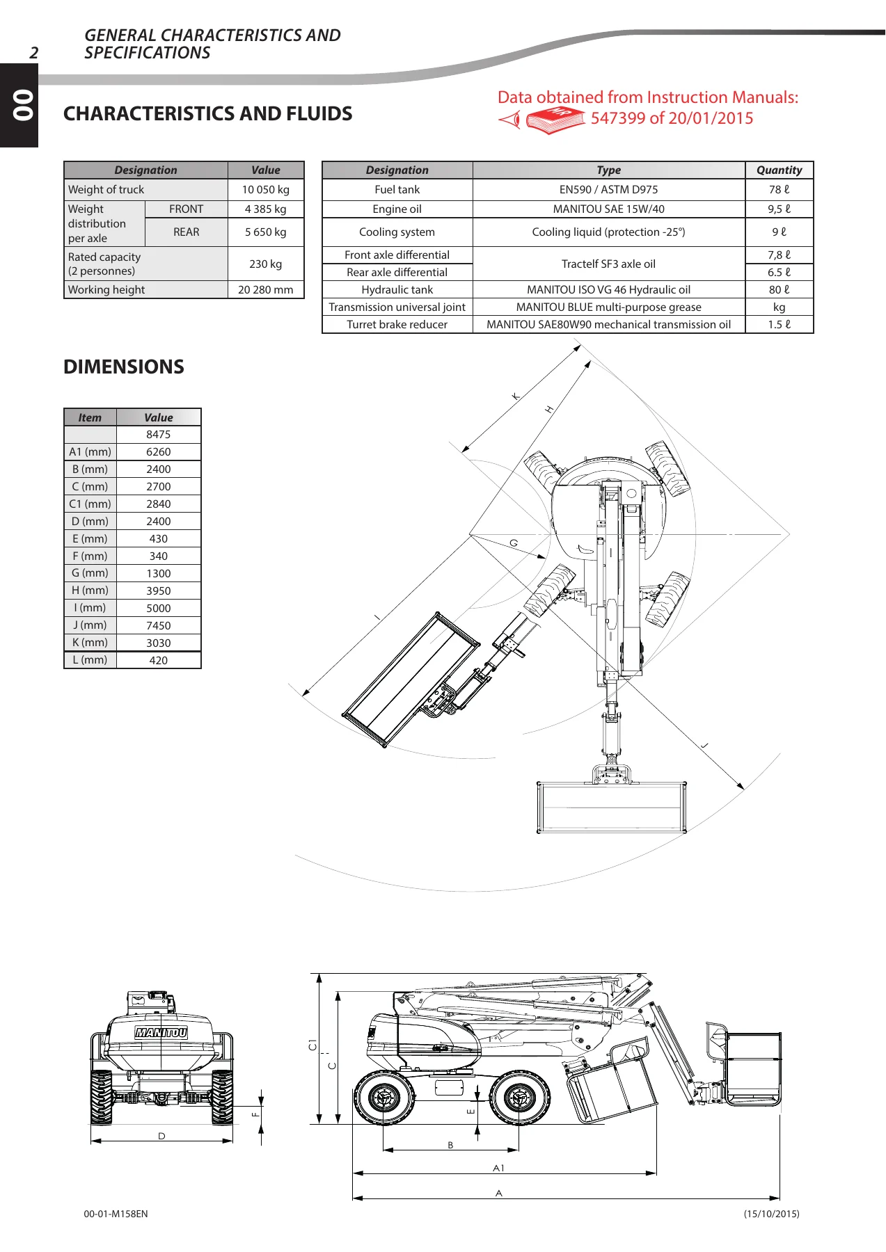
The specification section of this 200 ATJ service manual lists the operating data you need before any job: 10,050 kg machine weight, 4,385 kg front and 5,650 kg rear axle weight distribution, 230 kg rated capacity for two persons, and a 20,280 mm working height. Fluid and fill capacities are given for the fuel tank (EN590 / ASTM D975, 78 L), engine oil (MANITOU SAE 15W/40, 9.5 L), cooling system (9 L, protection to -25 degrees C), front axle differential (Tractelf SF3, 7.8 L / 6.5 L), hydraulic tank (MANITOU ISO VG 46 hydraulic oil, 80 L), and transmission universal joint and turret brake reducer lubricants. The dimension table provides the full A-to-L footprint measurements used for transport planning and site positioning.
General Control and Adjustment (Chapter 00)
Standard tightening torques for dry-fitted zinc-plated fasteners are tabulated for grade 8.8 and 10.9 hardware from M6 to M36, with coarse and fine pitch variants and the equivalent N.m and lb-in values. Adjustment coefficients are supplied for plate washers (+0 percent), spring or Grower washers without jaws (+10 percent), smooth tapered washers (+5 percent) and conical internal-tooth washers (+15 percent), so the correct torque can be calculated whenever a washer is introduced. A second table covers fasteners marked 4T through 11T with flange-specific values for use where flanged hardware is fitted.
Engine Control and Adjustment – Engine Removal and Refit (Chapter 10)
The engine chapter of this Manitou 200ATJ workshop manual covers both the solenoid version (up to machine no. 949266) and the electrovalve version (from no. 949267) of the proportional engine speed block. It walks through removal, refit and adjustment of the engine speed block, including the SNOW position (2500 rpm plus or minus 50) and SUN position (1250 rpm plus or minus 50) settings, with the manufacturer’s warning about maintaining a 1 mm minimum gap between the solenoid body and the adjustment screw. The engine removal procedure describes how to place the basket down, isolate the battery, open and secure the pivoting frame using the retaining rod, disconnect the alternator, starter, water temperature sensor, preheat, engine oil pressure sensor, hydrostatic pump control, ground, proportional engine speed block, engine speed sensor and engine stop valve harnesses. It then covers removing the air intake hose, complete air filter, side roll hoop, exhaust clamp and manifold, draining the radiator and engine block, and lifting the engine out with a hoist using the two slinging points (blue rings) rated at 250 kg. The refit section gives the tightening torques for the Silentblocs, engine bracket, coupling, flywheel casing, hydrostatic pump, auxiliary pump and HP flange screws.
Hydrostatic Pump Control and Adjustment – Removal (Chapter 20)
Covering the Rexroth A10VG hydrostatic pump and A2FM hydrostatic engine, this chapter details the pressure test ports (MB and MA for HP lines, X1 and X2 for pilot pressure, Fe for boost pressure, and R for case pressure) and adjustment points. Calibration procedures are given for the LP booster valve (target approximately 26 bar, with the note that adding 1 mm of shim raises pressure by approximately 4 bar), the servo-control piston neutral point (marked by the two points where the wheels begin to rotate in each direction), the HP valves (theoretical pressure 330 bar, with one turn of the setting screw changing pressure by approximately 45 bar) and the zero-flow DR valve (theoretical pressure 340 bar). The hydrostatic pump and hydrostatic engine removal and refit sections list the required tightening torques for the pump, auxiliary pump, coupling, Silentblocs and HP flange screws, and warn about the residual pressure in the hoses once the machine is shut down.
Transmission, Axle and Brake (Chapters 20 / 30 / 40)
The transmission chapter of this 200 ATJ repair manual covers hydrostatic pump removal and refit with the associated torque values, and the freewheel mode procedure for towing (hydrostatic clutch, rear axle mechanical clutch, and the 30 mm chocking dimension). The axle chapter covers front and rear axle removal, including oscillation lock cylinder handling on the option version, universal joint disassembly at both the front and rear axle ends, wheel removal, and the necessary lifting weights (front axle 405 kg, rear axle 520 kg, wheels 300 kg each). The brake and steering block, brake unit electrovalves, differential lock electrovalve and oscillation lock electrovalves are documented with their connector pinouts and fault codes. The chapter also includes the hydraulic schematic for the brake and steering block, and the electrovalve activation table.
Boom, Jib and Basket (Chapter 50)
The boom chapter of this Manitou 200 ATJ service manual covers the removal and refit of the telescope cylinder slide pads, arm 3 pads, moving tube pads and boom foot pads, with the adjustment plate positions noted and the 0.5 mm maximum clearance between the moving tube and the arm 3 slide pads. The jib and basket removal procedures describe how to remove the telescope cylinder, the flexible guide fasteners, the tilt cylinder foot and head pivot pins, the basket/jib/hinge assembly, and how to sling the assembly safely. The chapter also includes the basket rotation cylinder removal and refit, the freewheel mode procedure for towing, and the oscillating axle handling for the option version.
Hydraulic Characteristics and Specifications (Chapter 70)
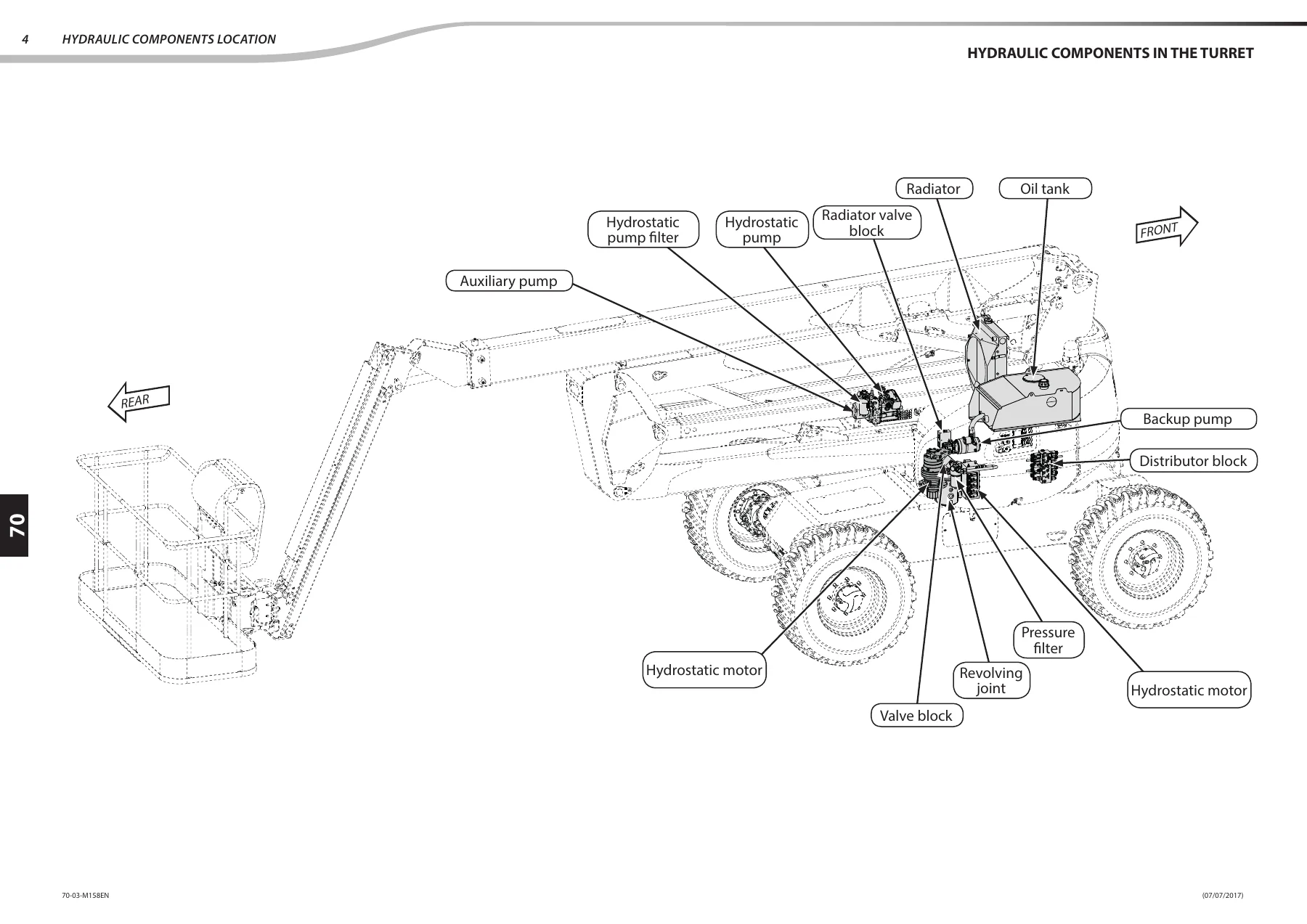
The hydraulic section of this 200ATJ workshop manual starts with component sheets for the proportional distributor PVG32 4T, the MA-250-CDC 016 distributor block, the brake and steering block distributor, the valve block and the generator block. The full hydraulic schematic is reproduced, together with the hydraulic components diagram key (oil tank, 6-passage rotary union, suction strainer, DANFOSS proportional distributor, variable displacement pump, bent-axis engine, distributor block, braking unit, pressure filter, suction filter, cooler, backup electric pump, radiator valve block, valve block, generator block, generator and engine speed proportional valve). The settings table lists flow rate and pressure values for the hydrostatic pump (112 L/min at 40/320 bar), booster pump (MAX 21 L/min at 26 bar), auxiliary pump (MAX 55.4 L/min at 200 bar), brake (0 L/min at 26 bar), differential lock (0 L/min at 26 bar), 2/4/crab steering (10 L/min at 170 bar), lower arm lifting (25 L/min at 200 bar), lower arm lowering (12 L/min at 100 bar), telescope extension (36 L/min at 100 bar), telescope retraction (18 L/min at 180 bar), upper arm lifting (16 L/min at 180 bar), upper arm lowering (7 L/min at 140 bar), function block proportional valve (170 bar), jib lifting (5 L/min at 170 bar), jib lowering (2 L/min at 80 bar), RH/LH steering (10 L/min at 170 bar), turret (4 L/min at 160 bar), basket rotation (1 L/min at 160 bar), cylinder extension (170 bar) and cylinder retraction (170 bar).
Electrical Characteristics and Specifications (Chapter 80)
The electrical section of this Manitou 200 ATJ repair manual starts with data sheets for the horn, rotating beacon light, levelling unit, fuel gauge, joysticks, ignition key, emergency stop buttons, overload sensor, axle detector, arm down sensor, retracted telescope sensor, hydraulic safety electrovalve, oscillation electrovalves, brake unit electrovalves, steering mode electrovalves, steering electrovalves, turret rotation electrovalves, basket rotation/inclination electrovalves, jib lifting electrovalves, pump electrovalve, accelerator electrovalve, generator electrovalve and proportional electrovalve control. Each sheet gives the connector pinout, voltage and current values, and the corresponding diagram. The section includes the full BRC 303 and BRC 30 wiring diagrams, the console wiring diagrams, the wiring diagrams by function (starter circuit, CAN circuit, transmission, proportional hydraulic movements, on/off hydraulic movements, sensors, lighting/signalling and overload), the position of electrical components by diagram, the position of fuses, electrovalves, pushbuttons and selector switches, indicator lamps, sensors, relays and engine components, and the BRC 303 and BRC 30 component location cards with their fuse and relay assignments. The electronic module descriptions cover the CEK 20 screen, the UPC 303 and UPC 30 computers, the UPC 101 and UPC 102 computers, and the BRC 303 and BRC 30 connection boxes.
Electrical Control and Adjustment (Chapter 80)
The control and adjustment section of this 200 ATJ service manual covers the operation of the lower console for both the up-to-949266 and from-949267 serial ranges. It documents the CEK 20 screen and keypad layout, the system settings page, the maintenance page, the fault history page, the maintenance history page, the input/output display pages, the fault management system, the summary list of faults, the table of parameters, and the generator calibration procedure. For machines from no. 949267, the section also covers the controls used on the base control panel, the menu structure, the access levels (User, Read Only, Dealer/Hirer, After-Sales Service, Manufacturer, MANITOU), the secret code menu, the settings menu, the maintenance menu, the calibration menu, the parameter management menu, the immobiliser option and the USB transfer option. Sensor adjustment procedures cover the tilt sensor (up to and from no. 949266), the overload sensor, the arm down sensor(s), the telescope retracted sensor(s) and the arm 3 sensor(s). The manipulator testing section explains how to test from the base control panel, how to test with a voltmeter, and how to perform the manipulator calibration.
Electrical Troubleshooting (Chapter 80)
The troubleshooting section of this Manitou 200 ATJ repair manual explains the fault codification principle, the creation of component type codes (SW for selector switch, PB for push button, JO for joystick, DS for digital sensor, IS for inductive sensor, AS for analog sensor, TS for tilt sensor, FS for frequency sensor, EW for PWM coil, EV for electrovalve), component identification by numeric location code (1xx for base, 2xx for structure, 3xx for basket, 4xx for remote controls), the creation of fault type codes (A for short circuit at start-up, B for non-neutral movement at start-up, C for open circuit, D for short circuit to positive, E for inconsistency, F for value outside range, G for high level, H for low level), the system fault types (S for communication, T for memory, U for functional warning, V for closed-loop control) and the maintenance fault types (L for late, N for to be carried out soon). The warning and fault code list covers over 100 fault codes from AC-110-A through UC-043-U, each with its full name and meaning, so you can interpret the CEK 20 display and trace the cause.
Why This 200 ATJ Repair Manual Is the Right Choice
Whether you are a Manitou dealer technician, an independent access platform engineer, or a fleet maintenance manager responsible for a MAN’ACCESS 200 ATJ, this repair manual gives you the manufacturer’s own procedures in one 266-page PDF. It supports every major job on the machine: engine speed block calibration, hydrostatic pump setup, axle removal, boom and telescope slide pad replacement, jib and basket removal, hydraulic pressure adjustment, electrical fault diagnosis, and sensor calibration. Having the correct procedures and specifications on hand is what separates a first-time fix from a repeat failure, and this document delivers both in a single reference.
IMAGES PREVIEW
Delivered as an instant PDF download after payment, with no shipping and no waiting. The file opens on any device – laptop, tablet or smartphone – and every page is printable, so you can take the relevant section out to the machine with you. One purchase, one file, and the complete factory repair procedure for the Manitou 200 ATJ in your hands in minutes.


Reviews
There are no reviews yet.