
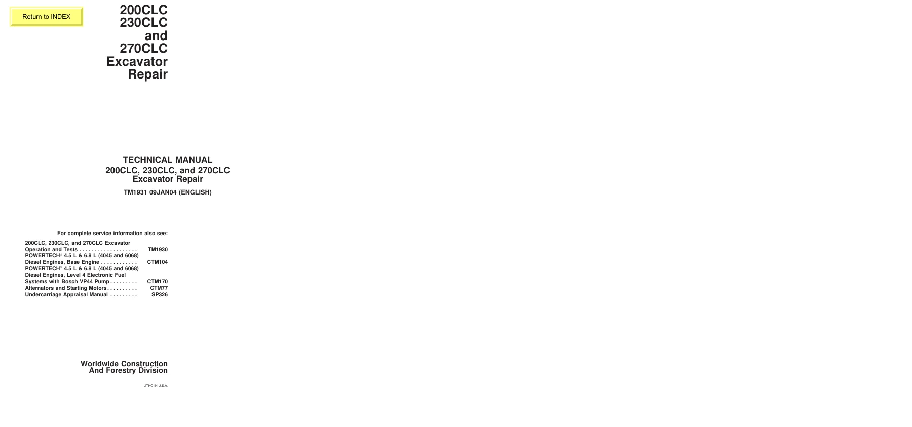
John Deere 200CLC 230CLC 270CLC Excavator Repair Technical Manual TM1931 PDF
Original price was: $34.95.$19.95Current price is: $19.95.
Complete John Deere repair technical manual TM1931 for 200CLC, 230CLC and 270CLC excavators. Covers tracks, propel, engine removal, hydraulics, swing system, operator station and dealer fabricated tools. Instant PDF download.
Description
John Deere 200CLC, 230CLC & 270CLC Excavator Repair Technical Manual TM1931
This is the complete repair technical manual TM1931 for the John Deere 200CLC, 230CLC and 270CLC excavators, published 09JAN04. It is written for the experienced technician and covers the procedures needed to disassemble, inspect, repair and reassemble the major systems of these machines. Whether you are rebuilding a final drive, replacing a track adjuster, resealing a hydraulic cylinder or removing the engine, this John Deere 200CLC, 230CLC and 270CLC Excavator Repair Technical Manual gives you the specifications and step-by-step procedures to do the job correctly.
File Details
- Manual Type: Repair Technical Manual
- Brand: John Deere
- Models Covered: 200CLC, 230CLC, 270CLC Excavators
- Publication Number: TM1931
- Date Published: 09JAN04
- Language: English
- File Format: PDF
- Page Count: Approximately 408 pages
Chapters Covered in the TM1931 Repair Manual
- Section 00 — General Information: Safety, Torque Values (inch and metric bolt and cap screw tables, O-ring boss fittings, flat face O-ring seal fittings, 37° flare and 30° cone seat connectors, four bolt flange fittings)
- Section 01 — Tracks: Track Roller, Front Idler, and Carrier Roller Oil; Track Roller Repair; Track Carrier Roller Repair; Metal Face Seals Repair; Track Shoe Repair; Track Chain Repair; Broken Track Chain Part Repair; Sprocket Repair; Front Idler Repair; Track Adjuster and Recoil Spring Repair; Track Adjuster Cylinder Repair
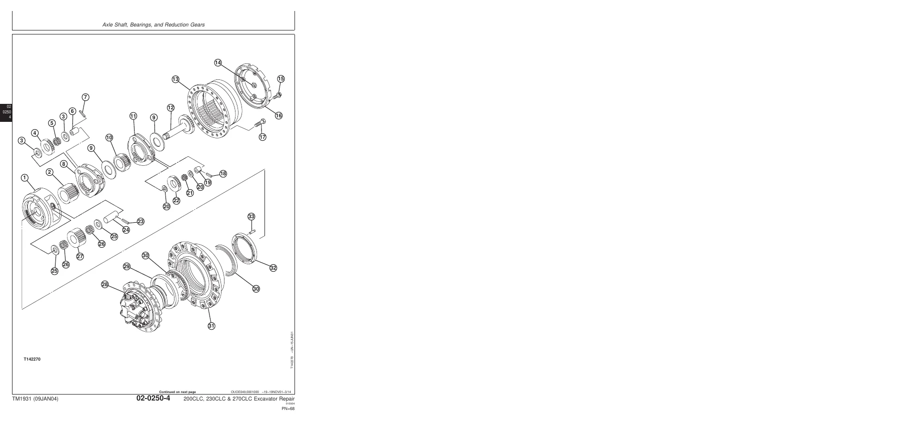
- Section 02 — Axles and Suspension Systems (Propel): Axle Shaft, Bearings and Reduction Gears (Propel Gearbox and Propel Motor); Hydraulic System (Rotary Manifold)
- Section 04 — Engine: Removal and Installation; Fuel Injection Pump Repair; Starter Repair
- Section 05 — Engine Auxiliary System: Cooling System (Radiator, Fan, Fan Guard and Fan Shroud, Fan Belt); Intake System (Air Intake System Leakage Test, Air Cleaner); External Fuel Supply System (Fuel Tank, Primary Fuel Filter/Water Separator, Final Fuel Filter)
- Section 07 — Dampener Drive (Flex Coupling): Elements
- Section 17 — Frame or Supporting Structure: Frame Installation, Welding Repair of Major Structure, Chassis Weights (Counterweight)
- Section 18 — Operator’s Station: Removal and Installation, Operator Enclosure (Windowpanes, Molding, Sliding Windows), Seat and Seat Belt, Heating and Air Conditioning (Compressor, Receiver-Dryer, Air Conditioner and Heater, Condenser, Refrigerant Recovery and Charging)
- Section 33 — Excavator: Buckets, Frames (Bucket Links, Arm, Boom, Pins/Bushings/Bosses), Hydraulic System (Hydraulic Pump and Drive Gearbox, Pilot Pump, Hydraulic Pump Regulator, Pilot Controller, Control Valve, Hydraulic Oil Tank, Oil Cooler, Boom/Arm/Bucket Cylinders)
- Section 43 — Swing or Pivoting System: Mechanical Drive Elements (Swing Gearbox, Upperstructure, Swing Bearing); Hydraulic System (Swing Motor and Park Brake, Crossover Relief Valve and Make-Up Valve, Brake Release Valve)
- Section 99 — Dealer Fabricated Tools: DF1063 Lift Bracket, ST4920 Track Recoil Spring Tool, DFT1087 Guard Tool, DFT1110 Spacer, DFT1130 Adapter, DF1036A Propel Gearbox Nut Wrench, DF1038 Torque Adapter, DFT1109 Holding Bar, Rotary Manifold Lifting Tool, DFT1089 Barrel Support, DFT1144 Guide Pin, DFT1119 Pump Support, DFT1220 Swing Gearbox Nut Spanner Wrench
Across roughly 408 pages, this John Deere 200CLC, 230CLC and 270CLC Excavator Repair Technical Manual goes well beyond a general overview. Each group opens with the essential tools, service equipment, materials, service parts kits, specifications, wear tolerances and torque values needed for that job, then walks through the disassembly, inspection, repair and assembly procedures using John Deere’s numbered callouts and exploded illustrations. Tracks, undercarriage and final drives are covered in detail, including metal face seal reuse criteria and track adjuster recoil spring compression values. The propel gearbox and motor are broken down for both the 200CLC/230CLC and the 270CLC design, with bearing preload, backlash limits and nut torque specs. The hydraulic system chapter covers the pump, regulators, control valve, cylinders and swing motor with the pressure and torque data needed to bring them back into specification.
Hydraulic, Track and Propel Repair for the 200CLC, 230CLC and 270CLC
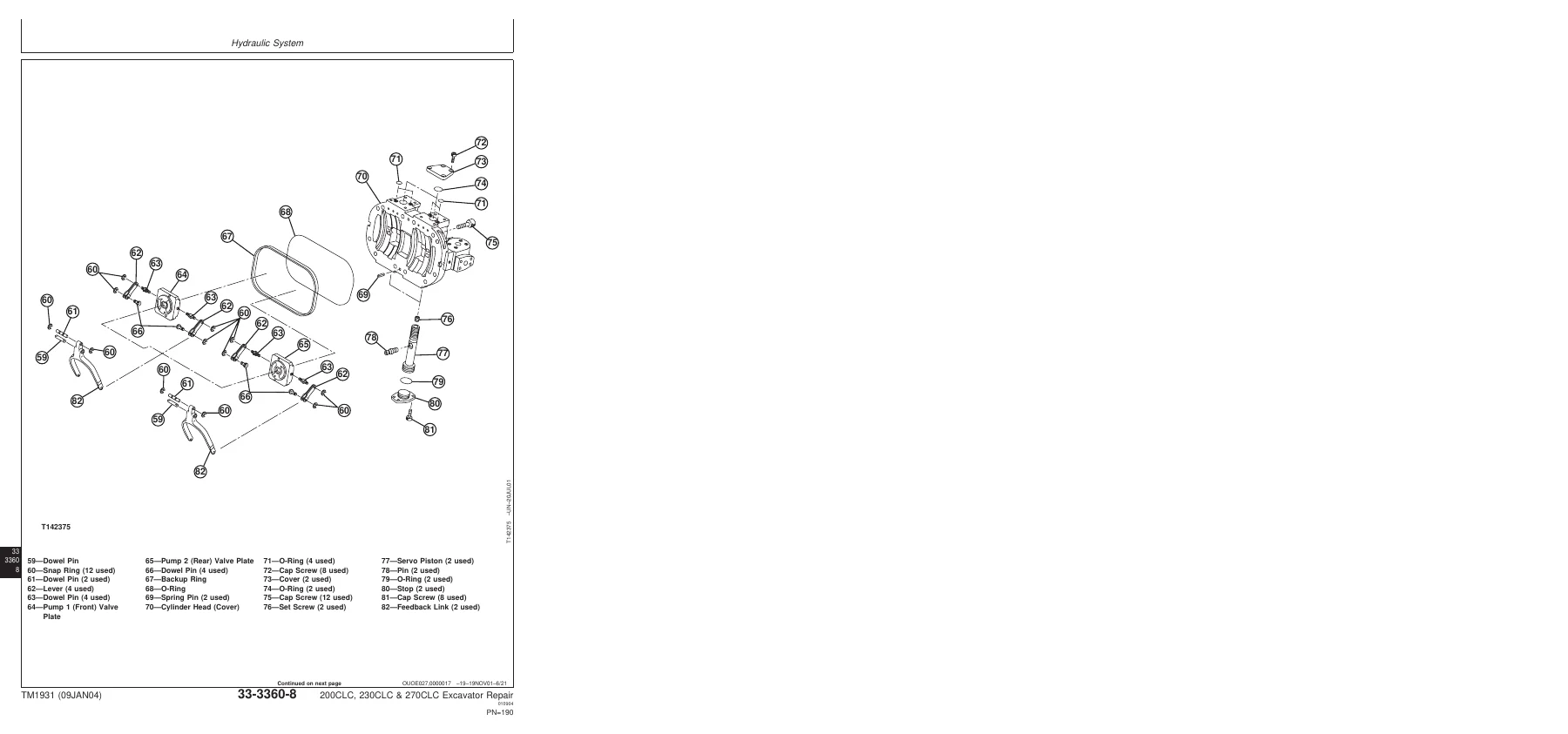
The Excavator section (Group 3360) is the largest part of the manual. It includes the hydraulic oil tank pressure release procedure, hydraulic oil cleanup using a portable filter caddy, hydraulic pump and drive gearbox disassembly, pump regulator disassembly, pilot pump, pilot pressure regulating valve, pilot shut-off valve, solenoid valves for power boost/propel speed/swing priority/arm regenerative, pilot controllers, pilot signal manifold, control valve (both 5-spool and 4-spool configurations), hydraulic oil tank, restriction valve, oil cooler bypass valve, oil cooler, and full disassembly/assembly of the boom, arm and bucket cylinders for each machine size. Cylinder repair sections give seal installation directions, piston nut torque (for example 4780 N·m for the 200CLC/270CLC boom piston nut and 10200 N·m for the arm piston nut), rod curvature limits, bushing wear limits and cap screw torque values.
The Tracks section covers the entire undercarriage. Track roller removal, disassembly, metal face seal inspection, oil fill volume (260 mL for track rollers) and a 110 kPa oil cavity air test are all documented. Front idler and carrier roller repair have their own procedures with oil fill volumes, air test pressures and cap screw torques. The track chain section covers turning pins and bushings, broken link repair, master pin identification and chain assembly, and the track adjuster and recoil spring procedure details the ST4920 compression tool, free length and compressed length values for 200CLC/230CLC and 270CLC, and the track adjuster cylinder seal replacement.
Engine, Operator Station and Swing System
The Engine section covers removal and installation of the engine with JDG23 Lifting Sling, engine mount cap screw torque (350 N·m), drive gearbox-to-flywheel housing torque, fuel injection pump removal notes and starter removal and installation. The Engine Auxiliary System covers the radiator, fan, fan guard, fan shroud, fan belt, air intake leakage test, air cleaner, fuel tank, primary fuel filter/water separator and final fuel filter with their removal and installation procedures.
The Operator’s Station section covers cab removal and installation, windowpane and molding repair (both two-piece and one-piece molding designs), sliding window repair, seat belt removal and installation, and the complete heating and air conditioning system including R134a refrigerant handling, system flushing, recovery, evacuation, charging (0.85 kg refrigerant charge), compressor, receiver-dryer, air conditioner and heater, and condenser. Refrigerant capacity, oil volume (210 mL) and torque values for the lines and components are all provided.
The Swing or Pivoting System section covers swing gearbox disassembly for both the 200CLC/230CLC design and the 270CLC design, upperstructure removal and installation, swing bearing disassembly and seal replacement, swing motor and park brake disassembly, inspection and assembly, and the crossover relief and make-up valve procedures. Bearing nut torque, ring gear cap screw torque, valve housing cap screw torque and piston/slipper/friction plate wear limits are all given.
Dealer Fabricated Tools and General Reference
Section 99 documents the special tools that John Deere recommends you build yourself to service these machines — the lift brackets, barrel supports, pump support, guide pin, gearbox nut wrenches, holding bars, torque adapters and track recoil spring tooling — with materials, dimensions and assembly notes. Section 00 provides the unified inch and metric cap screw torque tables, oil line and fitting service recommendations, and the O-ring boss, flat face O-ring seal, 37° flare, 30° cone seat and four bolt flange fitting torque charts that apply throughout the machine.
Why This TM1931 Repair Manual Matters
Working on a 20-ton class excavator without the manufacturer’s procedures and specifications is expensive guesswork. The John Deere 200CLC, 230CLC and 270CLC Excavator Repair Technical Manual TM1931 gives you the exact torque values, wear tolerances, clearances, oil capacities and assembly sequences for the 200CLC, 230CLC and 270CLC. It tells you when a metal face seal can be reused and when it must be replaced, which fasteners require thread lock and sealer, how to align a swing gearbox or propel gearbox during assembly, how to properly bleed air from a hydraulic cylinder to avoid cap seal damage, and how to pressurize the hydraulic oil tank safely before opening lines. The manual also covers the general safety messages and the safety signs used on the machine, so both the procedures and the precautions are documented in one place.
IMAGES PREVIEW
Instant PDF Delivery
This John Deere 200CLC, 230CLC and 270CLC Excavator Repair Technical Manual TM1931 is delivered as an instant PDF download — no shipping, no waiting. You can open it on any device (laptop, tablet, phone or desktop), search through it, zoom into diagrams, print the pages you need for the shop and keep a permanent copy on your computer or service truck. Once payment is complete you have immediate access to the same repair procedures and specifications used to keep these excavators running in the field.

Reviews
There are no reviews yet.