
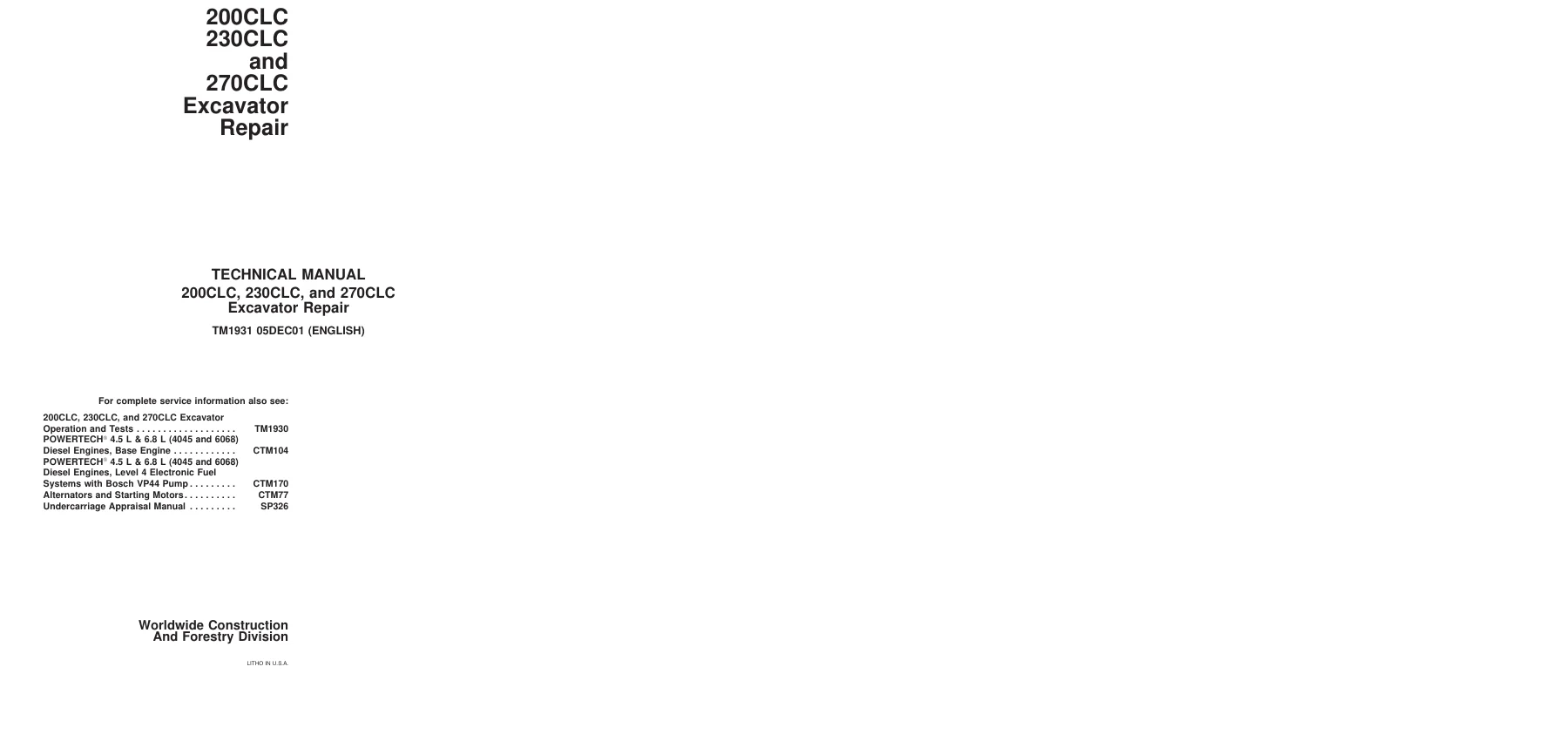
John Deere 200CLC 230CLC 270CLC Excavator Repair Technical Manual TM1931 PDF Download
Original price was: $52.95.$34.95Current price is: $34.95.
Complete John Deere 200CLC, 230CLC and 270CLC Excavator Repair Technical Manual TM1931 — 364-page PDF covering tracks, propel, engine, hydraulics, swing, cylinders, and dealer-fabricated tools with specifications, torque values, and wear limits.
Description
John Deere 200CLC, 230CLC and 270CLC Excavator Repair Technical Manual — TM1931
This is the complete John Deere 200CLC, 230CLC, and 270CLC Excavator Repair Technical Manual, publication TM1931, dated 05DEC01. It is written for the experienced technician and covers repair procedures, component disassembly and assembly, specifications, torque values, wear tolerances, and the essential tools required for each job. Whether you are rebuilding a final drive, resealing a boom cylinder, or tracking down a hydraulic fault, this manual gives you the actual procedures and numbers the job requires.
File Details
- Manual Type: Repair Technical Manual
- Brand: John Deere
- Models Covered: 200CLC, 230CLC, 270CLC Excavators
- Document Number: TM1931
- Publication Date: 05DEC01
- Language: English
- Page Count: 364 pages
- File Format: PDF
The manual also references related John Deere publications for complete service information: TM1930 (Operation and Tests), CTM104 and CTM170 (POWERTECH 4.5 L and 6.8 L diesel engines), CTM77 (alternators and starting motors), and SP326 (undercarriage appraisal).
Chapters Covered
The manual is organized into component groups, each beginning with a summary of applicable tools, service parts kits, specifications, wear tolerances, and torque values.
- Section 00 — General Information: Safety, Torque Values
- Section 01 — Tracks: Track System
- Section 02 — Axles and Suspension Systems (Propel): Axle Shaft, Bearings, Reduction Gears, Hydraulic System
- Section 04 — Engine: Removal and Installation
- Section 05 — Engine Auxiliary System: Cooling System, Intake System, External Fuel Supply System
- Section 07 — Dampener Drive (Flex Coupling): Elements
- Section 17 — Frame or Supporting Structure: Frame Installation, Chassis Weights
- Section 18 — Operator’s Station: Removal and Installation, Operator Enclosure, Seat and Seat Belt, Heating and Air Conditioning
- Section 33 — Excavator: Buckets, Frames, Hydraulic System
- Section 43 — Swing or Pivoting System: Mechanical Drive Elements, Hydraulic System
- Section 99 — Dealer Fabricated Tools
Section 00 — General Information
Covers safety alert symbols and signal words, personal protective equipment, machine inspection, high-pressure fluid hazards, fire prevention, battery safety, chemical handling, waste disposal, and emergency preparedness. The torque values group provides unified inch and metric bolt and cap screw torque tables, additional metric cap screw values, and detailed service recommendations for O-ring boss fittings, flat face O-ring seal fittings, 37° flare and 30° cone seat connectors, flared connections, and four-bolt flange fittings in both inch and metric series.
Section 01 — Tracks
Covers the complete track system: track roller removal, installation, disassembly and assembly; track roller oil specifications and leakage testing; carrier roller service; front idler removal, installation, disassembly, assembly, and leakage testing; metal face seal inspection and reuse criteria; track shoe removal and installation with torque-turn tightening patterns; track chain removal, installation, disassembly, assembly, and broken-part repair; sprocket removal and installation; track adjuster and recoil spring removal, installation, disassembly, and assembly; and track adjuster cylinder repair.
Section 02 — Axles and Suspension Systems (Propel)
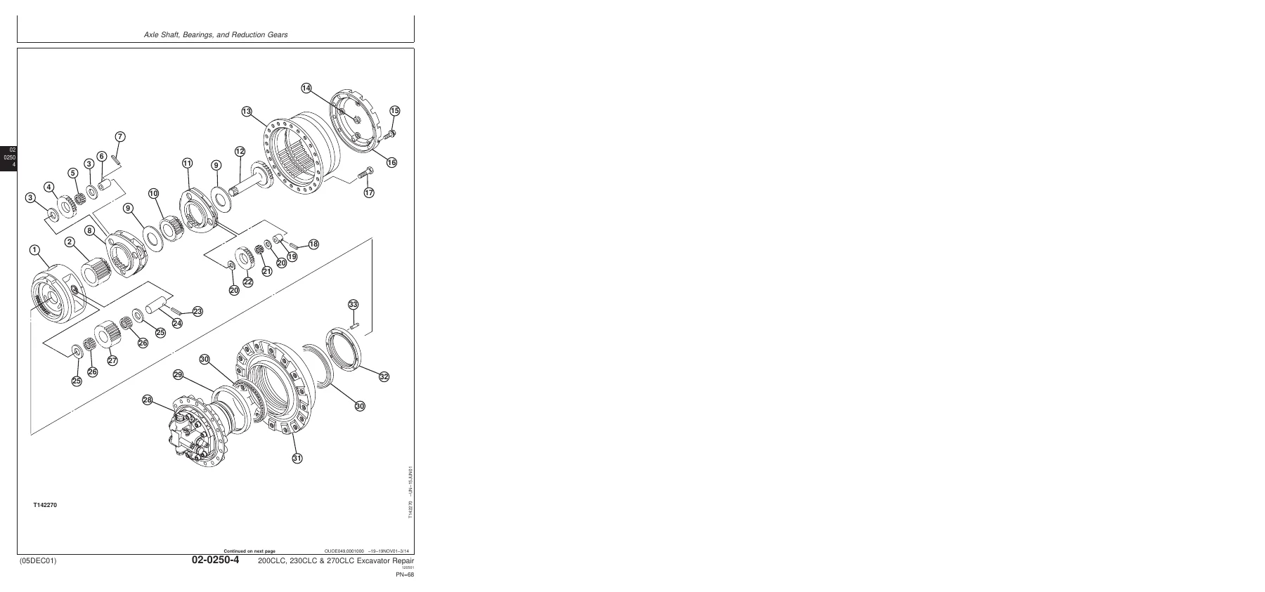
Covers propel gearbox and propel motor service for all three models. Includes gearbox removal and installation, disassembly and assembly of the 200CLC/230CLC and 270CLC propel gearboxes, bearing adjustment, metal face seal installation, and torque specifications for ring gear-to-drum, cover-to-ring gear, and gearbox-to-frame cap screws. Propel motor disassembly and assembly covers 200CLC, 230CLC, and 270CLC variants, including brake piston removal, friction plate and plate inspection, piston-to-bore clearances, and motor cover valve service. Also covers rotary manifold removal, installation, disassembly, assembly, and air testing.
Section 04 — Engine
Covers engine removal and installation procedures, including disconnecting battery ground, draining coolant, removing fan guard, radiator shroud, fan blade, charge air cooler hoses, radiator hoses, air intake hose, muffler and bracket, engine wiring, air conditioner compressor bracket, fuel system pressure relief, fuel lines, heater hoses, and supporting the main hydraulic pump and drive gearbox. Includes the JDG23 Lifting Sling requirements and engine mount torque values. Also covers fuel injection pump removal and installation and starter removal and installation.
Section 05 — Engine Auxiliary System
Covers radiator removal and installation with capacity specifications; fan, fan guard, and fan shroud service; fan belt removal and installation; air intake system leakage testing; air cleaner removal and installation; fuel tank removal and installation with capacity and torque values; primary fuel filter (water separator) removal and installation; and final fuel filter removal and installation with electrical connector and line details.
Section 07 — Dampener Drive (Flex Coupling)
Covers flex coupling removal and installation, including coupling-to-pump shaft set screw torque, insert-to-flywheel and coupling cap screw torque, and the alignment of the spring pin for insert-to-flywheel positioning.
Section 17 — Frame or Supporting Structure
Covers welding repair of major structure with weld process specifications, preheat temperatures, and tensile/yield strength requirements. Also covers counterweight removal and installation with model-specific weights and frame-to-counterweight cap screw torque values.
Section 18 — Operator’s Station
Covers cab removal and installation with weight and mounting torque values; windowpane service including two-piece molding, one-piece molding, and sliding windows; windowpane replacement with urethane adhesive procedures; seat belt removal and installation; and the complete heating and air conditioning system including refrigerant cautions, R134a handling, system flushing and purging, refrigerant oil information, recovery/recycling and charging station installation, recovery, evacuation, charging, compressor service, receiver-dryer service, air conditioner and heater unit service, and condenser service.
Section 33 — Excavator
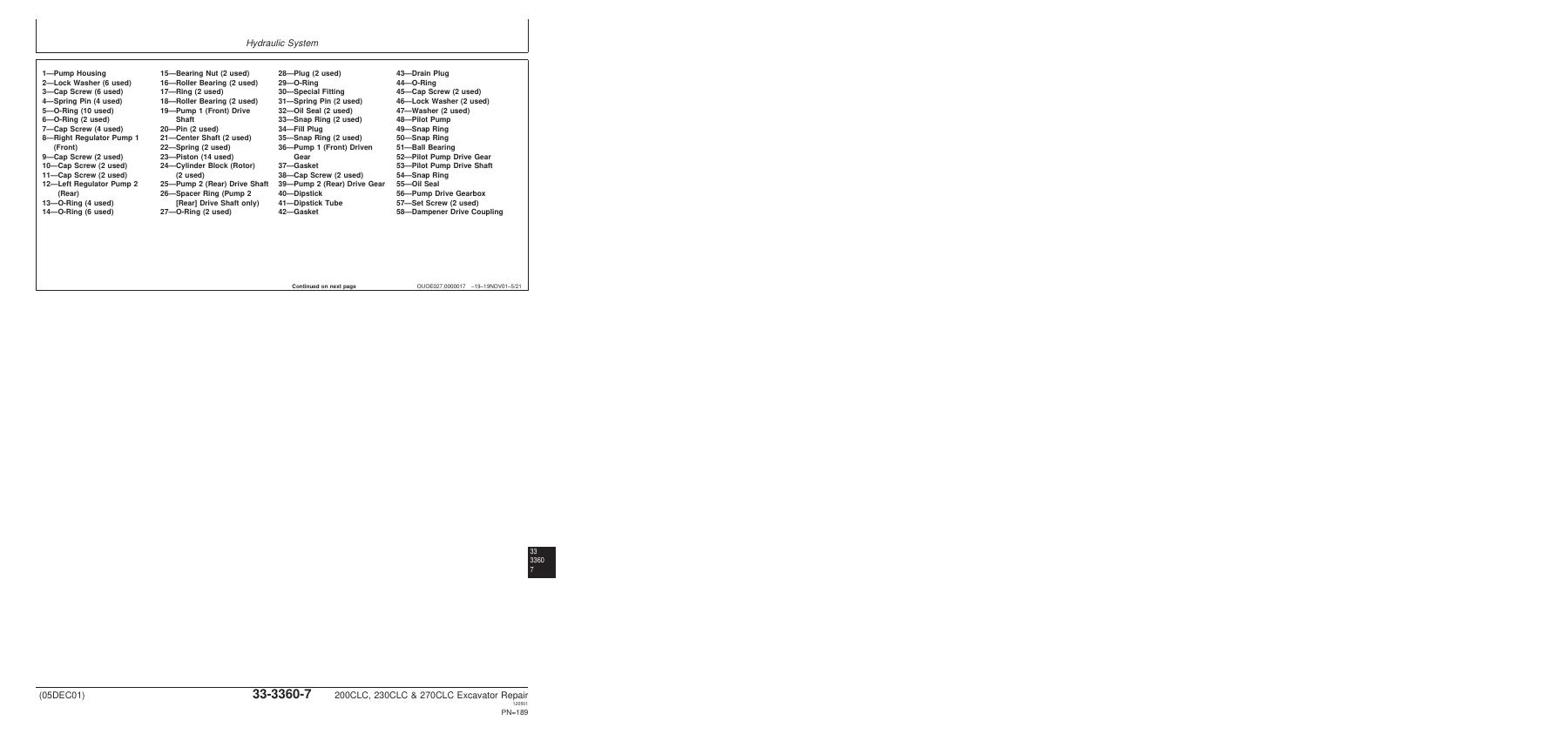
This is the largest section, covering buckets, frames, and the hydraulic system. Bucket group covers bucket removal and installation, pivot end play adjustment, and pin-up data. Frames group covers bucket links, arm, boom, inspection of boom/arm/bucket pins, bushings and bosses, and bushings and seals repair. Hydraulic system group covers hydraulic oil tank vent procedure, hydraulic oil cleanup using a portable filter caddy, hydraulic pump and drive gearbox repair and start-up, pilot pump drive shaft and gear, hydraulic pump regulator, pilot pump, pilot pressure regulating valve and filter, pilot shut-off valve, power boost/propel speed/swing priority/arm regenerative solenoid valves, pilot controller, propel pilot controller, pilot signal manifold, control valve (5-spool and 4-spool), hydraulic oil tank, restriction valve, oil cooler bypass valve, oil cooler, boom cylinder, arm cylinder, bucket cylinder, hydraulic cylinder bleed procedure, and cylinder disassembly and assembly.
Section 43 — Swing or Pivoting System
Mechanical drive elements group covers swing gearbox removal and installation, disassembly and assembly for 200CLC/230CLC and 270CLC, start-up procedure, upperstructure removal and installation, and swing bearing removal, installation, disassembly, assembly, and seal service. Hydraulic system group covers swing motor and park brake removal, installation, disassembly, assembly, inspection, and start-up; crossover relief valve and make-up valve removal, installation, and disassembly; and brake release valve service for 270CLC.
Section 99 — Dealer Fabricated Tools
Provides drawings, materials, and dimensions for dealer-fabricated tools used in the procedures above, including DF1063 Lift Bracket, ST4920 Track Recoil Spring Disassembly and Assembly Tool, DFT1087 Track Recoil Spring Guard Tool, DFT1110 Spacer, DFT1130 Adapter, DF1036A Propel Gearbox Nut Wrench, DF1038 Torque Adapter, DFT1109 Holding Bar, Rotary Manifold Lifting Tool, DFT1089 Barrel Support, DFT1144 Guide Pin, DFT1119 Pump Support, and DFT1220 Swing Gearbox Nut Spanner Wrench.
What This Manual Enables You To Do
With the John Deere 200CLC, 230CLC, and 270CLC Excavator Repair Technical Manual in hand, you can perform the full range of service work these machines require. The manual is built for the experienced technician, but the level of detail makes it equally valuable for the serious owner-operator or shop that needs the right numbers and the right procedures the first time.
You get the actual torque values for critical fasteners — track shoe cap screws, sprocket-to-propel gearbox bolts, swing bearing cap screws, cylinder rod guide cap screws, piston-to-rod nuts, and dozens more. You get wear tolerances and service limits for bushings, pins, bearings, friction plates, disc springs, and seal surfaces, so you can measure and decide whether a part is reusable or must be replaced. You get the exact procedures for metal face seal installation, including the cleaning and lubrication requirements that determine whether a resealed component will leak.
The hydraulic content is especially deep. The control valve section covers the 5-spool and 4-spool housings, spool select-fit requirements, relief and anti-cavitation valves, lift checks, flow rate valves, and the torque values for every cartridge and plug. The hydraulic pump section covers cylinder block, piston, drive shaft, bearing, and regulator service with nominal and limit-of-use clearances. The cylinder section covers boom, arm, and bucket cylinders with seal installation notes, cushion and cushion seal orientation, rod curvature limits, rod scratch depth limits, and the cap seal installation method that prevents seal damage during assembly.
Undercarriage work is covered in full: track roller, carrier roller, front idler, track shoe, track chain, sprocket, track adjuster, recoil spring, and the metal face seal inspection criteria that tells you whether a used seal can be reused or must be replaced as a matched set.
Propel and swing systems get the same treatment. The propel gearbox and motor sections cover planetary carriers, sun gears, ring gears, drums, bearings, bearing nut adjustment, metal face seals, brake pistons, friction plates, and the valve cover assemblies. The swing gearbox and motor sections cover the same level of detail, including bearing nut torque, lock plate alignment, and seal installation.
Every procedure is supported by the specifications, torque values, and wear limits printed in the manual — not generic advice. When the manual says a bushing is at its limit of use at a specific inside diameter, that is the number you measure against. When it gives a torque-turn specification for track shoe cap screws, that is the tightening sequence you follow.
IMAGES PREVIEW
Instant PDF Delivery
This is a digital PDF download. There is no shipping, no waiting for a physical book, and no risk of a damaged or lost package. After purchase, you can download the file immediately and open it on any device — laptop, desktop, tablet, or smartphone. The PDF can be printed if you prefer a paper copy in the shop, and you can print only the sections you need for a particular job. Keep it on a shop computer for quick reference, or load it onto a tablet and take it to the machine. The complete John Deere 200CLC, 230CLC, and 270CLC Excavator Repair Technical Manual is one download away, ready to help you get the job done correctly.

Reviews
There are no reviews yet.