
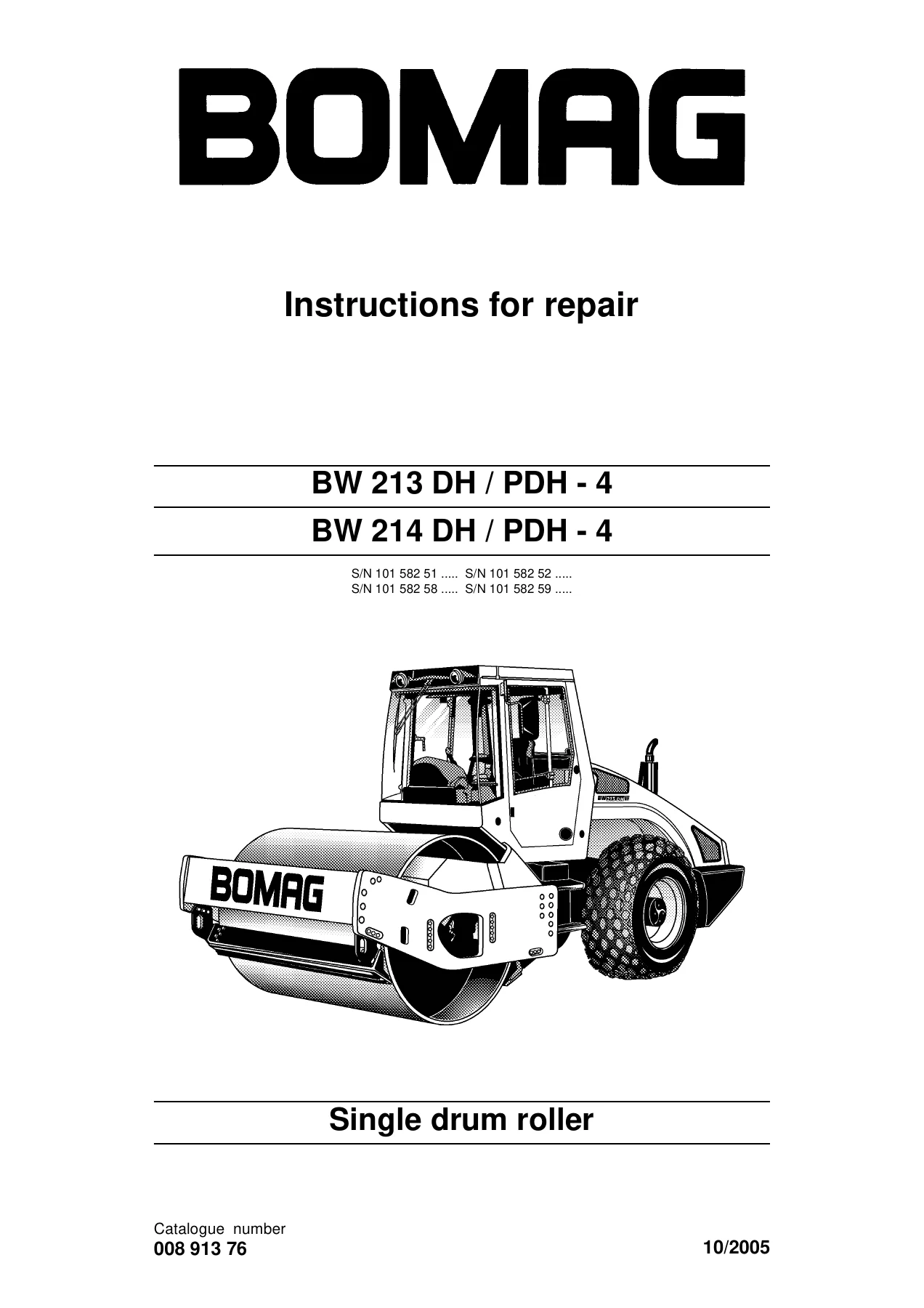
BOMAG BW 213 DH/PDH-4 & BW 214 DH/PDH-4 Single Drum Roller Repair Manual 2005
Original price was: $39.95.$24.95Current price is: $24.95.
Complete BOMAG repair manual for BW 213 DH/PDH-4 and BW 214 DH/PDH-4 single drum rollers — engine, travel, vibration, steering, drum, articulated joint, electrics, hydraulics and circuit diagrams.
Description
BOMAG BW 213 DH/PDH-4 & BW 214 DH/PDH-4 Single Drum Roller Repair Manual
This BOMAG BW 213 DH/PDH-4 & BW 214 DH/PDH-4 repair manual is the full workshop document for the fourth-generation single drum rollers, issued by BOMAG GmbH in 2005 under document number 008 913 76. It covers the BW 213 DH-4, BW 213 PDH-4, BW 214 DH-4 and BW 214 PDH-4 machines, and takes a skilled mechanic through removal, dismantling, inspection, repair, assembly and adjustment of every major assembly group on the machine. Whether you are diagnosing a fault code on the ESX control, resealing a Sauer-Danfoss 90R travel pump, re-shimming the oscillating articulated joint, replacing drum rubber buffers or tracing a hydraulic circuit, this is the reference document that pairs the correct procedure with the correct measured value.
File Details
- Manual type: Instructions for repair (workshop / service manual)
- Brand: BOMAG
- Models covered: BW 213 DH-4, BW 213 PDH-4, BW 214 DH-4, BW 214 PDH-4
- Document number: 008 913 76
- Publication year: 2005
- Language: English
- File format: PDF
- Serial numbers covered: S/N 101 582 51, 101 582 52, 101 582 58, 101 582 59
Chapters Covered
- 1 General — 1.1 Foreword, 1.2 Safety regulations, 1.3 General repair instructions, 1.4 Tightening torques, 1.5 Connection overview, 1.6 Technical data, 1.7 Table of fuels and lubricants
- 2 Tests and adjustments — 2.1 Special tools, 2.2 Activate service mode, 2.3 Driving against the closed brake, 2.4 Check the engine speed, 2.5 Pressure tests in the travel circuit, 2.6 Checking / adjusting the neutral position of the travel pump, 2.7 Pressure measurements in the vibration circuit, 2.8 Check the leakage rate of the vibration motor, 2.9 Pressure test in steering circuit
- 3 Flushing and bleeding — 3.1 Special tools for flushing, 3.2 Flushing general, 3.3 Flushing schematic travel circuit (distribution travel pump), 3.4 Flushing the travel circuit (travel pump distribution), 3.5 Flushing schematic travel circuit (distribution axle motor), 3.6 Flushing the travel circuit (axle motor distribution), 3.7 Flushing schematic for vibration drive, 3.8 Flushing the vibration circuit, 3.9 Bleeding the travel circuit, 3.10 Bleeding the vibration circuit
- 4 Technical Manual — 4.1 Technical Manual / Basic Electrics, 4.2 Technical Manual / Electrics, 4.3 Technical Manual / DH/PDH (Deutz BF4M1013EC EMR engine, travel system, vibration, steering)
- 5 Air conditioning system — safety notes, refrigerant R134a, compressor oil, refrigeration diagram, component description, compressor oil level, magnetic clutch, V-belt, servicing, drying and evacuation, leak test, filling instructions, heating / air-conditioning control
- 6 Replacing the cab window panes — assembly of window panes, special tools, auxiliary materials, removing and installing
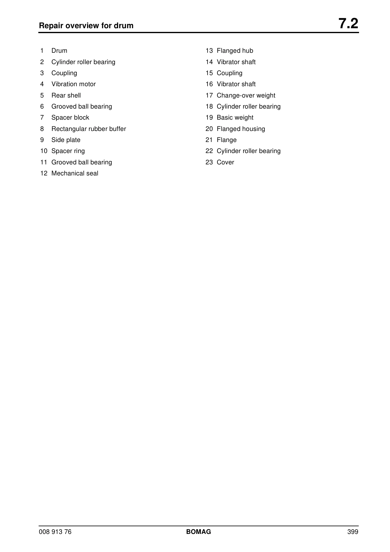
- 7 Drum — 7.1 Special tools, 7.2 Repair overview, 7.3 Removing and installing the drum, 7.4 Repairing the drum, 7.5 Dismantling / assembling the change-over weights, 7.6 Changing the rubber buffers and adjusting the pretension
- 8 Oscillating articulated joint — 8.1 Special tools, 8.2 Repair overview, 8.3 Removing and installing, 8.4 Dismantling, 8.5 Assembling
- 9 Suppliers documentation — 9.1 Travel pump / vibration pump series 90R, 9.2 Vibration motor A2FM, 9.3 Travel drive series 51, 9.4 Transmission CR, 9.5 Axle DANA 193
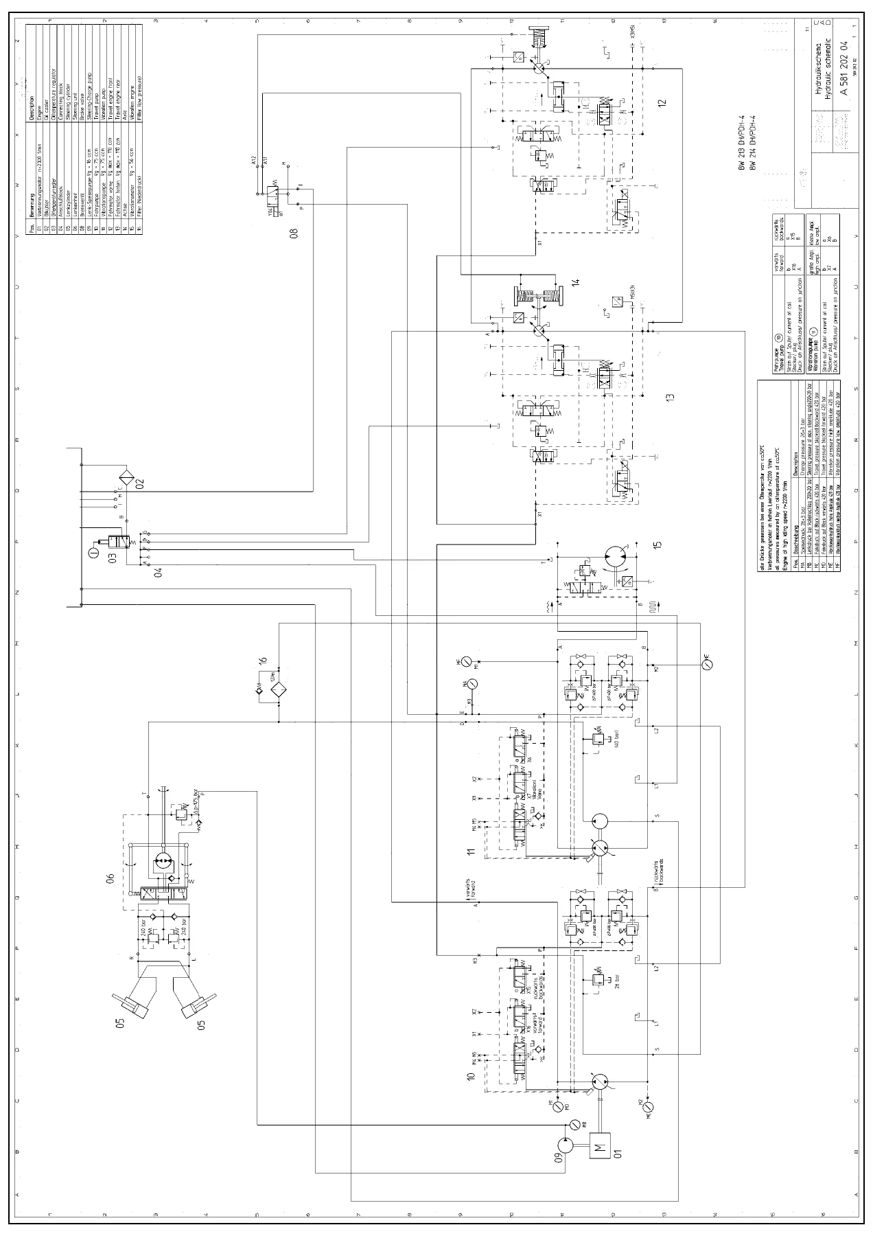
- 10 Circuit diagrams — 10.1 Wiring diagram, 10.2 Hydraulic diagram
Read as a whole, this manual gives a technician the complete architecture of the BW 213 DH/PDH-4 and BW 214 DH/PDH-4: the hydrostatic travel circuit with its closed-loop pump and motor control, the vibration circuit with high and low amplitude change-over, the load-sensing steering system, the drum with its exciter shaft and elastically suspended rubber buffers, the oscillating articulated joint that keeps drum and wheels on the ground through extreme curves, and the full electrical backbone — ESX controller, EMR engine management, LCD display, sensors and proportional solenoids. The Suppliers Documentation section adds the OEM-level bench information for the Sauer-Danfoss 90R075 tandem pump, the Bosch-Rexroth A2FM 56 HDD vibration motor, the Sauer-Danfoss 51C110 / 51D110 travel motors, the CR 31 reduction gear and the DANA 193 rear axle, so you are not working from generic aftermarket assumptions. The circuit diagrams at the back — wiring and hydraulic — are what make the diagnostic chapters usable in practice.
What this repair manual helps you do
The BOMAG BW 213 DH/PDH-4 & BW 214 DH/PDH-4 repair manual is written around the jobs that actually fail on these machines. If the roller creeps with the travel lever in neutral, the neutral-position chapter walks you through the closed-brake test setup, the X1/X2 control-chamber bridging hose and the mechanical adjustment on the travel pump. If a fault code appears on the LC display, the Electrics and DH/PDH technical sections decode the code, point to the signal path and give you the nominal voltage or current at the connector. If the drum has lost amplitude or is noisy, the vibration chapter takes you through pump pressures, multi-function valve behaviour and the leakage rate test at the vibration motor. If the drum rubs or the machine feels loose, the drum and articulated joint chapters cover rubber buffer replacement, pretension shimming, rocker bearing preload and end-float values. If the steering wanders, the steering circuit chapter covers the OSPC 500 ON valve, the anti-cavitation and shock valves, and the steering cylinder isolation test that separates a cylinder fault from a pump fault.
Beyond repair, this is also the reference for correct specification. The tightening torque tables in Chapter 1, the technical data and adjustment values by machine type in Chapter 1.6, the charge pressure and high-pressure limits in the travel and vibration circuits, the valve clearance settings, injection valve opening pressure, refrigerant charge and compressor oil quantity, filling capacities for engine oil, hydraulic oil, axle, wheel hubs, reduction gear and vibration bearing housings — all of it is here so the machine goes back together to BOMAG’s figures, not to a guess. Measuring and adjustment values are repeated at the point of work in the relevant chapter, which means you can follow a procedure without flipping back and forth.
Flushing and bleeding gets its own full chapter because it is where most hydraulic repairs go wrong on a closed-circuit roller. The manual gives schematics for flushing the travel circuit with either travel-pump or axle-motor distribution, and for the vibration circuit, including the flushing filter installation, hose routing, the correct travel direction to use during the flush, and the full bleed sequence for both circuits. Skipping this step is how chips from a failed pump or motor end up in a brand-new component — the manual treats it as a mandatory procedure, and this is the document that tells you exactly how to do it.
Why this manual matters
The BW 213 DH/PDH-4 and BW 214 DH/PDH-4 are hydrostatically driven, electronically controlled machines. That means the failure modes are not the ones a mechanical roller owner expects — a fault can sit in a proportional solenoid, a speed sensor, a CAN line, an EMR actuator or a pressure override valve just as easily as in a mechanical linkage. Working on them without the manufacturer’s procedures and nominal values is how parts get replaced that were never faulty, and how good parts get damaged during the job. This repair manual closes that gap. It contains the ESX input codes, the service-mode access procedure, the teach functions for travel system surge currents and steering, the electronic end-stop teaching, the machine-type coding, and the fault-code structure — the diagnostic depth that makes the difference between a repair and a parts swap.
For the DH/PDH variants specifically, the manual also covers the PDH (padfoot drum) machines alongside the smooth drum DH versions in the same technical data tables, so owners of either machine type get the correct figures for their roller rather than an approximation. The engine is the Deutz BF4M1013EC EMR throughout, and the engine chapter covers the EMR II system, plug assignments for the X30/X31/X57 connectors, sensors, actuator, heating flange and the valve clearance and plug-in injection pump procedures for the Deutz unit.
Instant PDF delivery
The BOMAG BW 213 DH/PDH-4 & BW 214 DH/PDH-4 single drum roller repair manual is delivered as a PDF download immediately after payment — no shipping, no waiting for a disc, no customs. You can open it on a workshop laptop, a tablet on the machine, or a phone in the cab, and you can print the pages you need for the job in front of you. The circuit diagrams in particular are worth printing at size for fault tracing. Once downloaded, the file is yours to keep and reference for every service, repair and rebuild on the machine.

Reviews
There are no reviews yet.