★ TRUSTED BY 321,897+ PROFESSIONALS WORLDWIDE
🏢
Trusted Business
Verified & Licensed
🛡️
Virus Free Files
100% Safe Downloads
🔒
Secure Payment
SSL Protected
Instant Delivery
Available Immediately
Sale!

John Deere 410J Backhoe Loader Repair Technical Manual TM10851 – PDF Download

Original price was: $39.95.Current price is: $24.95.

Complete John Deere 410J Backhoe Loader Repair Technical Manual TM10851 covering engine, transmission, axles, hydraulics, brakes, loader, and backhoe service for machines serial number 161617 and up.

Instant PDF Download
Available immediately
💾
Save to Your Device
Download & keep forever
🛡️
Antivirus Scanned
100% virus-free
🌍
Trusted Worldwide
175,000+ customers

Description

John Deere 410J Backhoe Loader Repair Technical Manual TM10851

This is the complete Repair Technical Manual for the John Deere 410J Backhoe Loader, published under document number TM10851 and dated 22 December 2015. It is written for the experienced technician and covers machines from serial number 161617 and above. Every system on the machine is addressed in its own dedicated group, with summary listings of the essential tools, service equipment, other materials, service parts kits, specifications, wear tolerances, and torque values needed before the work begins. Whether you are resealing a boom cylinder, pulling the transmission, disassembling the MFWD axle, or chasing a hydraulic fault, this John Deere 410J repair technical manual gives you the on-the-job procedures John Deere expects your shop to follow.

File Details

  • Manual type: Repair Technical Manual
  • Publication number: TM10851
  • Publication date: 22 December 2015 (ENGLISH)
  • Brand: John Deere
  • Model: 410J Backhoe Loader
  • Serial number coverage: 410J (S.N. from 161617)
  • Language: English
  • Format: PDF
  • Page count: 787 pages

Chapters Covered

The 410J repair technical manual is divided into the same sectional layout John Deere uses across its backhoe loader platform. The listing below follows the table of contents so you can see at a glance which group contains the procedure you need.

Complete PDF Bookmark Tree

Complete Bookmarks

The complete bookmarks in the “John Deere 410J Backhoe Loader Repair Technical Manual TM10851 – PDF Download” are as follows:

Table of contentsp. 2
FOREWORDp. 5
TECHNICAL INFORMATION FEEDBACK FORMp. 6
Section 00 – GENERAL INFORMATIONp. 9
Group 0001 – Safety Informationp. 9
Recognize Safety Informationp. 9
Follow Safety Instructionsp. 9
Operate Only If Qualifiedp. 9
Wear Protective Equipmentp. 11
Avoid Unauthorized Machine Modificationsp. 11
Inspect Machinep. 11
Stay Clear of Moving Partsp. 12
Avoid High-Pressure Fluidsp. 12
Avoid High-Pressure Oilp. 13
Beware of Exhaust Fumesp. 13
Prevent Firesp. 14
Prevent Battery Explosionsp. 15
Handle Chemical Products Safelyp. 15
Dispose of Waste Properlyp. 15
Prepare for Emergenciesp. 16
Use Steps and Handholds Correctlyp. 16
Start Only From Operator′s Seatp. 16
Use and Maintain Seat Beltp. 17
Prevent Unintended Machine Movementp. 17
Prevent Unintended Machine Movement—If Equipped With Pilot Controlsp. 18
Avoid Work Site Hazardsp. 18
Keep Riders Off Machinep. 19
Avoid Backover Accidentsp. 19
Avoid Machine Tipoverp. 21
Add and Operate Attachments Safelyp. 21
Use Special Care When Operatingp. 21
Operating or Traveling On Public Roadsp. 22
Inspect and Maintain ROPSp. 23
Prevent Unintended Detonation of Explosive Devicesp. 23
Park and Prepare for Service Safelyp. 23
Service Cooling System Safelyp. 24
Remove Paint Before Welding or Heatingp. 24
Make Welding Repairs Safelyp. 25
Drive Metal Pins Safelyp. 25
Service Tires Safelyp. 27
Group 0003 – Torque Valuesp. 28
Metric Bolt and Cap Screw Torque Valuesp. 28
Additional Metric Cap Screw Torque Valuesp. 29
Unified Inch Bolt and Cap Screw Torque Valuesp. 31
Service Recommendations for 37° Flare and 30° Cone Seat Connectorsp. 32
Service Recommendations for O-Ring Boss Fittingsp. 33
O-Ring Boss Fittings In Aluminum Housing Service Recommendations—Excavatorsp. 35
Service Recommendations For Flared Connections—Straight or Tapered Threadsp. 37
Service Recommendations For Flat Face O-Ring Seal Fittingsp. 39
O-Ring Face Seal Fittings With SAE Inch Hex Nut And Stud End For High Pressure Service Recommendationsp. 40
O-Ring Face Seal Fittings With Metric Hex Nut And Stud End For Standard Pressure Service Recommendationsp. 42
O-Ring Face Seal Fittings With Metric Hex Nut And Stud End For High Pressure Service Recommendationsp. 44
Service Recommendations for Metric Series Four Bolt Flange Fittingp. 46
Service Recommendations For Inch Series Four Bolt Flange Fittingsp. 47
Inch Series Four Bolt Flange Fitting For High Pressure Service Recommendationsp. 48
Service Recommendations For Non-Restricted Banjo (Adjustable) Fittingsp. 49
Service Recommendations For O-Ring Boss Fittings With Shoulderp. 51
Metric 24° O-Ring Seal DIN 20078 Service Recommendationsp. 54
Section 01 – WHEELSp. 59
Group 0110 – Powered or Non-Powered Wheels and Fasteningsp. 59
Rear Wheel Assembly Remove and Installp. 59
Front Wheel Assembly Remove and Installp. 61
Tire Remove and Installp. 62
Section 02 – AXLES AND SUSPENSION SYSTEMSp. 66
Group 0225 – Input Drive Shafts and U-Jointsp. 66
Universal Joint and Drive Shaft Remove and Installp. 66
Group 0230 – Non-Powered Wheel Axlesp. 70
Hub Assembly Remove and Installp. 70
Spindle Assembly Remove and Installp. 72
Tie Rod Remove and Installp. 74
Non-Powered Front Axle Remove and Installp. 76
Group 0240 – Powered Wheel Axle (MFWD)p. 79
Mechanical Front Wheel Drive (MFWD) Axle Remove and Installp. 79
Mechanical Front Wheel Drive (MFWD) Axle Disassemblep. 82
Mechanical Front Wheel Drive (MFWD) Axle Assemblep. 97
Open Differential Disassemble and Assemble—If Equippedp. 123
Limited Slip Differential Disassemble and Assemble—If Equippedp. 129
Group 0250 – Axle Shaft, Bearings, and Reduction Gearsp. 138
Service Brakes Inspectionp. 138
Rear Axle Remove and Installp. 140
Rear Axle Disassemblep. 143
Park Brake Disassemble and Assemblep. 155
Rear Axle Assemblep. 169
Gear Tooth Contact Pattern Checkp. 189
Section 03 – TRANSMISSIONp. 191
Group 0300 – Removal and Installationp. 191
Transmission Removep. 191
Transmission Installp. 198
Group 0315 – Controls Linkagep. 204
Transmission Control Lever (TCL) Remove and Installp. 204
Group 0350 – Gears, Shafts, and Power Shift Clutchesp. 205
Remove Outer Components to Disassemble Transmissionp. 205
Torque Converter Side of Transmission Case Disassemblep. 209
Clutch Packs Removep. 212
High Range Forward, Low Range Forward, and Reverse Clutch Packs Disassemble and Assemblep. 217
First Speed and Third Speed Clutch Disassemble and Assemblep. 233
Second Speed Clutch Disassemble and Assemblep. 249
Mechanical Front Wheel Drive (MFWD) Clutch Disassemble and Assemblep. 265
Pump Drive Shaft Installp. 274
Clutch Packs Installp. 276
Torque Converter Side of Transmission Case Assemblep. 281
Install Outer Components to Assemble Transmissionp. 286
Group 0360 – Hydraulic Systemp. 290
Transmission Charge Pump Remove and Installp. 290
Transmission Charge Pump Disassemble and Assemblep. 293
Section 04 – ENGINEp. 296
Group 0400 – Removal and Installationp. 296
PowerTech and PowerTech E 4.5 L and 6.8 L John Deere Enginesp. 296
Engine Removep. 297
Engine Installp. 308
PowerTech and PowerTech E 4.5 L and 6.8 L John Deere Engines—Stage II Enginesp. 316
Engine Remove—Stage II Enginep. 317
Engine Install—Stage II Enginep. 324
Section 05 – ENGINE AUXILIARY SYSTEMSp. 331
Group 0505 – Cold Weather Starting Aidp. 331
Coolant Heater Remove and Installp. 331
Starting Aid Nozzle Remove and Installp. 332
Starting Aid Nozzle Remove and Install—Stage II Enginep. 333
Starting Aid Solenoid Remove and Installp. 334
Group 0510 – Cooling Systemp. 336
Fan Remove and Installp. 336
Fan Belt Remove and Installp. 338
Radiator Remove and Installp. 340
Fan Remove and Install—Stage II Enginep. 345
Fan Belt Remove and Install—Stage II Enginep. 347
Radiator Remove and Install—Stage II Enginep. 349
Group 0515 – Speed Controlsp. 354
Engine Speed Control Pedal Remove and Installp. 354
Group 0520 – Intake Systemp. 355
Air Cleaner Remove and Installp. 355
Air Cleaner Remove and Install—Stage II Enginep. 357
Charge Air Cooler Remove and Installp. 359
Group 0530 – Exhaust Systemp. 361
Muffler With Turbocharger Remove and Installp. 361
Muffler With Turbocharger Remove and Install—Stage II Enginep. 363
Group 0560 – External Fuel Supply Systemp. 365
Fuel Tank Remove and Installp. 365
Auxiliary Water Separator Fuel Filter Remove and Install—If Equippedp. 368
Section 06 – TORQUE CONVERTERp. 371
Group 0651 – Turbine, Gears and Shaftp. 371
Torque Converter Remove and Installp. 371
Torque Converter Disassemble and Assemblep. 372
Section 09 – STEERING SYSTEMp. 374
Group 0960 – Hydraulic Systemp. 374
Steering Column Remove and Installp. 374
Standard Steering Wheel and Column Disassemble and Assemblep. 378
Tilt Steering Wheel and Column Disassemble and Assemblep. 380
Steering Valve Remove and Installp. 382
Steering Valve Disassemble and Assemblep. 389
Non-Powered Front Axle Steering Cylinder Repairp. 394
Mechanical Front Wheel Drive (MFWD) Axle Steering Cylinder Disassemble and Assemblep. 398
Section 10 – SERVICE BRAKESp. 405
Group 1011 – Active Elementsp. 405
Service Brake External Inspectionp. 405
Brake Disk and Pressure Plate Remove and Installp. 405
Group 1060 – Hydraulic Systemp. 406
Brake Valve Remove and Installp. 406
Brake Valve Disassemble and Assemblep. 411
Brake Valve Lines Disassemble and Assemblep. 418
Brake Pedals Remove and Installp. 420
Brake Pedal Adjustmentp. 422
Brake Bleeding Procedurep. 423
Section 11 – PARK BRAKEp. 428
Group 1111 – Active Elementsp. 428
Park Brake Remove and Installp. 428
Section 17 – FRAME OR SUPPORTING STRUCTUREp. 430
Group 1740 – Frame Installationp. 430
Welding Repair of Major Structuresp. 430
RIVNUT RIVNUT is a registered trademark of The BF Goodrich Co. (KREMNUT) Fasteners Remove and Installp. 431
Main Frame Bushings Remove and Installp. 434
Group 1749 – Chassis Weightsp. 435
Counterweight Remove and Installp. 435
Section 18 – OPERATOR’S STATIONp. 439
Group 1800 – Removal and Installationp. 439
Cab/ROPS Remove and Installp. 439
Group 1810 – Operator Enclosurep. 455
Front Window Wiper and Wiper Motor Remove and Installp. 455
Rear Window Wiper and Wiper Motor Remove and Installp. 458
Front Cab Windowpane Remove and Installp. 461
Fixed Windowpanes Remove and Installp. 462
Cab Door and Side Window Disassemble and Assemblep. 463
Cab Door Hinges and Latch Adjustmentp. 466
Upper Cab Door and Side Windowpanes Adjustmentp. 468
Upper Cab Door and Side Window Latch Adjustmentp. 469
Rear Windows Remove and Installp. 470
Headliner Remove and Installp. 472
Cab Roof Remove and Installp. 473
Group 1821 – Seat and Seat Beltp. 475
Seat Assembly Remove and Installp. 475
Seat and Arm Rest Disassemble and Assemblep. 476
Seat Belt Disassemble and Assemblep. 478
Seat Slide, Lumbar Support, and Adjuster Control Levers Disassemble and Assemblep. 480
Seat Swivel and Swivel Latch Disassemble and Assemblep. 482
Seat Suspension and Shock Absorber Disassemble and Assemblep. 484
Air Suspension Seat Disassemble and Assemble—If Equippedp. 486
Group 1830 – Heating and Air Conditioningp. 493
Proper Refrigerant Handlingp. 493
R134a Refrigerant—Cautionsp. 493
R134a Refrigerant Theory Of Operationp. 494
Refrigerant Hoses and Tubing Inspectionp. 495
Air Conditioner Compressor Remove and Installp. 496
R134a Compressor Oil Checkp. 498
R134a Compressor Oil Removal Procedurep. 498
R134a Component Oil Charge Procedurep. 499
Compressor Clutch Disassemble and Assemblep. 501
Clutch Hub Clearance Checkp. 502
Compressor Manifold Inspectp. 503
Air Conditioning Compressor Disassemble and Assemblep. 505
R134a Refrigerant Recover, Recycle, and Charge Station Installation Procedurep. 508
R134a System Recover Procedurep. 510
R134a System Evacuate Procedurep. 512
R134a System Charge Procedurep. 515
R134a System Cleaning Procedurep. 516
R134a System Leak Testingp. 517
Heater Core Remove and Installp. 518
Evaporator Remove and Installp. 522
R134a System Flush Procedurep. 526
R134a System Purge Procedurep. 528
Air Conditioning Freeze Switch Remove and Installp. 530
Heater/Blower Assembly with Air Conditioning and Pressurizer System Disassemble and Assemblep. 533
Air Ducts Disassemble and Assemblep. 536
Condenser Disassemble and Assemblep. 538
Receiver Dryer Remove and Installp. 541
Expansion Valve—Remove and Installp. 543
Section 19 – SHEET METAL AND STYLINGp. 546
Group 1910 – Hood and Engine Enclosurep. 546
Hood and Engine Enclosure Disassemble and Assemblep. 546
Group 1913 – Miscellaneous Shieldsp. 549
Battery Box Disassemble and Assemblep. 549
Group 1921 – Grille and Grille Housingp. 551
Grille and Grille Housing Disassemble and Assemblep. 551
Group 1927 – Fendersp. 553
Fenders and Cab Skirts Remove and Install—If Equippedp. 553
Section 20 – SAFETY, CONVENIENCE AND MISCELLANEOUSp. 555
Group 2001 – Radiop. 555
Radio Remove and Installp. 555
Antenna Remove and Installp. 556
Radio Speakers and Antenna Remove and Installp. 557
Group 2004 – Horn and Warning Devicesp. 559
Horn Remove and Installp. 559
Backup Alarm Remove and Installp. 560
Backup Alarm Volume Adjustmentp. 561
Section 21 – MAIN HYDRAULIC SYSTEMp. 563
Group 2160 – Hydraulic Systemp. 563
Hydraulic Pump Remove and Installp. 563
Hydraulic Pump Disassemble and Assemblep. 567
Hydraulic Pump Control Disassemble and Assemblep. 569
Power Limiting Valve Remove and Installp. 572
Hydraulic Filter Assembly Remove and Installp. 574
Hydraulic Reservoir Remove and Installp. 576
Hydraulic Reservoir Disassemble and Assemblep. 579
Hydraulic and Transmission Oil Coolers Remove and Installp. 581
Section 31 – LOADERp. 589
Group 3100 – Loaderp. 589
Loader Boom Remove and Installp. 589
Group 3102 – Bucketp. 593
Loader Bucket Remove and Installp. 593
Loader Bucket Cutting Edge Crack Repairp. 593
Loader Bucket Cutting Edge Remove and Installp. 595
Loader Multi-Purpose Bucket and Lines Disassemble and Assemblep. 600
Group 3104 – Attachment Couplerp. 602
Attachment Coupler Remove and Installp. 602
Attachment Coupler Cylinder Remove and Installp. 603
Attachment Coupler Cylinder Disassemble and Assemblep. 604
Group 3115 – Control Linkagesp. 605
Loader Control Valve Linkage Remove and Installp. 605
Third Function Loader Control Valve Linkage Remove and Installp. 607
Stabilizer Linkage Remove and Installp. 609
Loader Bucket Linkage Remove and Installp. 612
Group 3160 – Hydraulic Systemp. 614
Loader and Stabilizer Control Valve Remove and Installp. 614
Loader and Stabilizer Control Valve Disassemble and Assemblep. 617
Loader and Stabilizer Control Valve Relief Valves Remove and Installp. 622
Loader and Stabilizer Control Valve Load Sense Relief Valve Disassemble and Assemblep. 624
Loader Boom Raise and Bucket Curl Circuit Relief Valve Disassemble and Assemblep. 626
Loader Bucket Dump Circuit Relief Valve with Anticavitation Disassemble and Assemblep. 627
Loader Anticavitation Valve Disassemble and Assemblep. 627
Loader Auxiliary Circuit Relief Valve Disassemble and Assemblep. 629
Loader Auxiliary Shutoff Plug Disassemble and Assemblep. 629
Loader Bucket Cylinder Remove and Installp. 631
Loader Bucket Cylinder Disassemble and Assemblep. 632
Loader Multi-Purpose Bucket Cylinder Disassemble and Assemblep. 632
Loader Boom Cylinder Remove and Installp. 634
Loader Boom Cylinder Disassemble and Assemblep. 635
Ride Control Valve Remove and Installp. 636
Ride Control Valve Disassemble and Assemblep. 639
Ride Control Valve Solenoid Disassemble and Assemblep. 640
Ride Control Accumulator Remove and Installp. 642
Section 33 – BACKHOEp. 646
Group 3302 – Bucketp. 646
Backhoe Bucket and Bucket Links Remove and Installp. 646
Backhoe Bucket Tooth Tips Remove and Installp. 646
Backhoe Bucket Tooth Shank Remove and Installp. 648
Backhoe Bucket Cutting Edge Remove and Installp. 651
Group 3315 – Control Linkagep. 653
Backhoe Control Valve Linkage—Two Lever Remove and Installp. 653
Backhoe Control Valve Linkage—Three Lever Remove and Installp. 655
Backhoe Fifth Function Pedal Remove and Installp. 658
Backhoe Sixth Function Pedal Remove and Installp. 662
Backhoe Pilot Control Valve Remove and Installp. 666
Backhoe Pilot Control Valve Disassemble and Assemblep. 670
Backhoe Pilot Control Tower Remove and Installp. 679
Backhoe Pilot Control Tower Disassemble and Assemblep. 681
Backhoe Boom Lock Control Lever and Linkage Remove and Installp. 684
Backhoe Boom Lock Remove and Installp. 686
Group 3340 – Framesp. 688
Dipperstick Remove and Installp. 688
Boom Remove and Installp. 691
Swing Frame Remove and Installp. 693
Extendible Dipperstick Extension Remove and Installp. 695
Group 3360 – Hydraulic Systemp. 702
Backhoe Control Valve Remove and Installp. 702
Backhoe Control Valve Disassemble and Assemblep. 707
Backhoe Control Valve Spool Seals Remove and Installp. 710
Backhoe Control Valve Relief Valves Remove and Installp. 715
Backhoe Inlet Section Disassemble and Assemblep. 717
Backhoe Flow Control Section Disassemble and Assemblep. 719
Backhoe Swing Section Disassemble and Assemblep. 723
Backhoe Boom Section Disassemble and Assemblep. 729
Backhoe Bucket Section Disassemble and Assemblep. 735
Backhoe Crowd Section Disassemble and Assemblep. 741
Backhoe Extendible Dipperstick Section Disassemble and Assemblep. 747
Backhoe Outlet Section Disassemble and Assemblep. 750
Pilot Control Manifold Valve Remove and Install (S.N. —178748)p. 752
Pilot Control Manifold Valve Disassemble and Assemble (S.N. —178748)p. 754
Pilot Enable and Pattern Select Valve Remove and Install (S.N. 178749— )p. 755
Pilot Enable and Pattern Select Valve Disassemble and Assemble (S.N. 178749— )p. 757
Pattern Select Valve Remove and Install (S.N. —178748)p. 759
Pattern Select Valve Disassemble and Assemble (S.N. —178748)p. 762
Backhoe Bucket Cylinder Remove and Installp. 763
Backhoe Bucket Cylinder Disassemble and Assemblep. 764
Backhoe Crowd Cylinder Remove and Installp. 765
Backhoe Crowd Cylinder Disassemble and Assemblep. 766
Backhoe Boom Cylinder Remove and Installp. 767
Backhoe Boom Cylinder Disassemble and Assemblep. 768
Backhoe Swing Cylinder Remove and Installp. 769
Backhoe Swing Cylinder Disassemble and Assemblep. 771
Backhoe Stabilizer Cylinder Remove and Installp. 772
Backhoe Stabilizer Cylinder Disassemble and Assemblep. 773
Backhoe Extendible Dipperstick Cylinder Remove and Installp. 774
Backhoe Extendible Dipperstick Cylinder Disassemble and Assemblep. 775
Section 38 – GRAPPLEp. 777
Group 3800 – Backhoe Hydraulic Thumbp. 777
Hydraulic Thumb Remove and Install—If Equippedp. 777
Group 3860 – Backhoe Hydraulic Thumb Cylinderp. 779
Hydraulic Thumb Cylinder Remove and Install—If Equippedp. 779
Hydraulic Thumb Cylinder Disassemble and Assemble—If Equippedp. 781
Section 99 – DEALER FABRICATED TOOLSp. 783
Group 9900 – Dealer Fabricated Toolsp. 783
DFRW20 Compressor Holding Fixturep. 783
DFT1101 Cab and ROPS Lift Bracketp. 784
DFT1285 Engine Support Bracketp. 785
DFT1286 Backlash Measurement Toolp. 787

  • Section 00 – General Information: Safety Information, Torque Values
  • Section 01 – Wheels: Powered or Non-Powered Wheels and Fastenings
  • Section 02 – Axles and Suspension Systems: Input Drive Shafts and U-Joints, Non-Powered Wheel Axles, Powered Wheel Axle (MFWD), Axle Shaft, Bearings, and Reduction Gears
  • Section 03 – Transmission: Removal and Installation, Controls Linkage, Gears, Shafts, and Power Shift Clutches, Hydraulic System
  • Section 04 – Engine: Removal and Installation
  • Section 05 – Engine Auxiliary Systems: Cold Weather Starting Aid, Cooling System, Speed Controls, Intake System, Exhaust System, External Fuel Supply System
  • Section 06 – Torque Converter: Turbine, Gears and Shaft
  • Section 09 – Steering System: Hydraulic System
  • Section 10 – Service Brakes: Active Elements, Hydraulic System
  • Section 11 – Park Brake: Active Elements
  • Section 17 – Frame or Supporting Structure: Frame Installation, Chassis Weights
  • Section 18 – Operator’s Station: Removal and Installation, Operator Enclosure, Seat and Seat Belt, Heating and Air Conditioning
  • Section 19 – Sheet Metal and Styling: Hood and Engine Enclosure, Miscellaneous Shields, Grille and Grille Housing, Fenders
  • Section 20 – Safety, Convenience and Miscellaneous: Radio, Horn and Warning Devices
  • Section 21 – Main Hydraulic System: Hydraulic System
  • Section 31 – Loader: Loader, Bucket, Attachment Coupler, Control Linkages, Hydraulic System
  • Section 33 – Backhoe: Bucket, Control Linkage, Frames, Hydraulic System
  • Section 38 – Grapple: Backhoe Hydraulic Thumb, Backhoe Hydraulic Thumb Cylinder
  • Section 99 – Dealer Fabricated Tools: Dealer Fabricated Tools

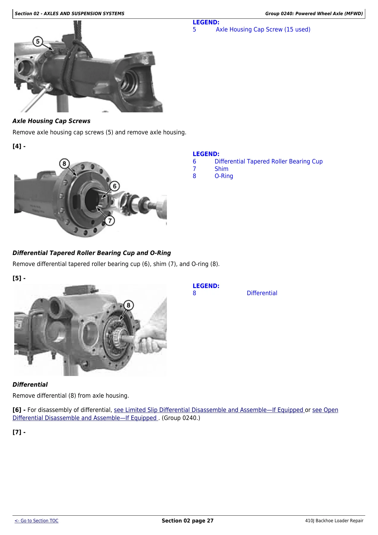
For a technician who already knows how a backhoe loader works, this John Deere 410J repair manual is the reference that closes the gap between general familiarity and factory procedure. It shows you how the torque converter bolts to the flywheel through the flexplate, how the transmission case halves separate and which clutch packs come out together, how the MFWD axle carrier and ring gear are pressed apart and how shim thickness is calculated from the housing stamping, and how the backhoe control valve sections are stacked and torqued so spools do not bind. Rather than a walkthrough that assumes one particular failure, this technical manual TM10851 gives you the disassembly, inspection, and reassembly sequence John Deere designed for the machine, plus the torque and clearance numbers that decide whether the repair holds up.

IMAGES PREVIEW

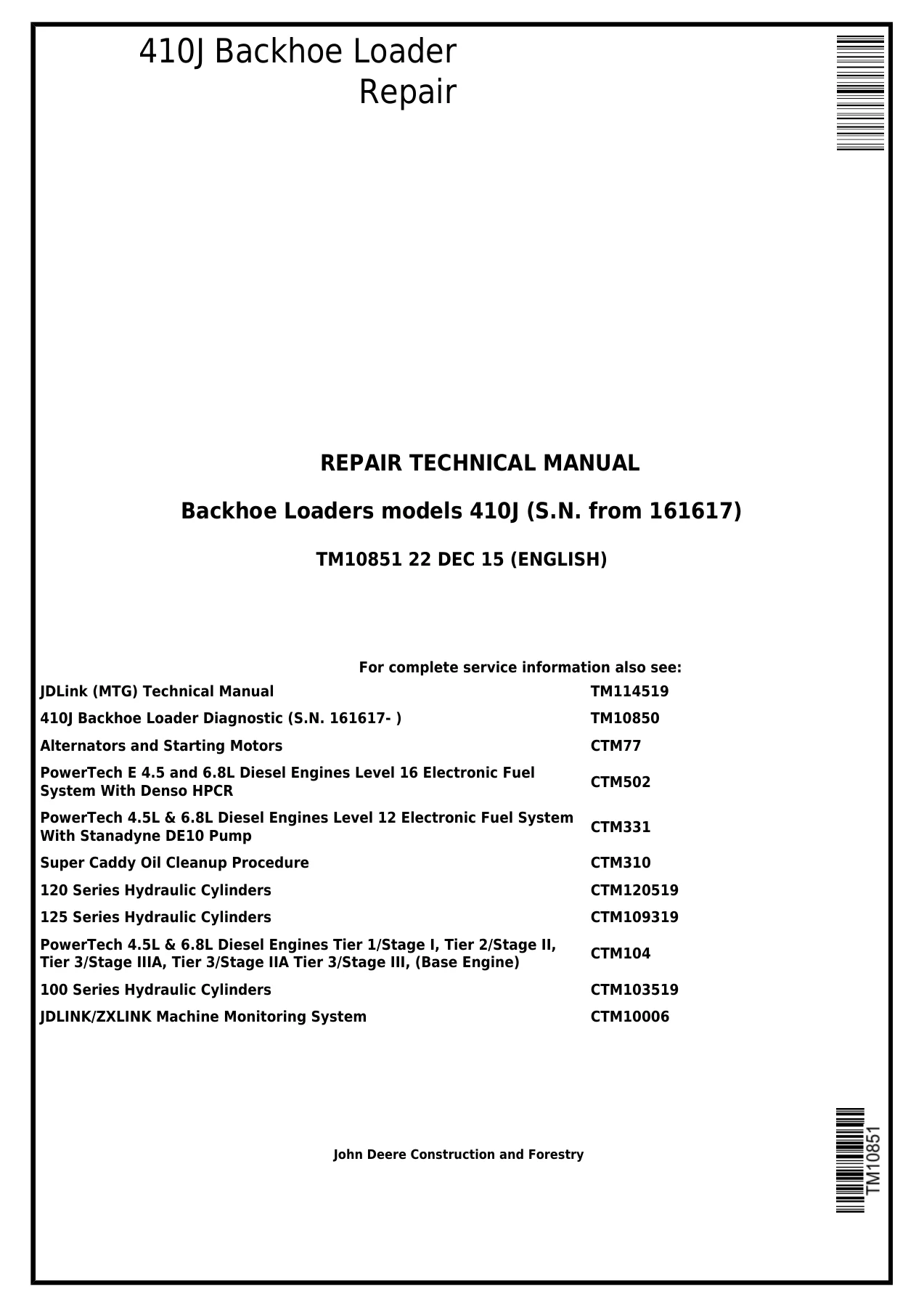
John Deere 410J Backhoe Loader Repair Technical Manual TM10851 - PDF Download — PDF page 1 preview
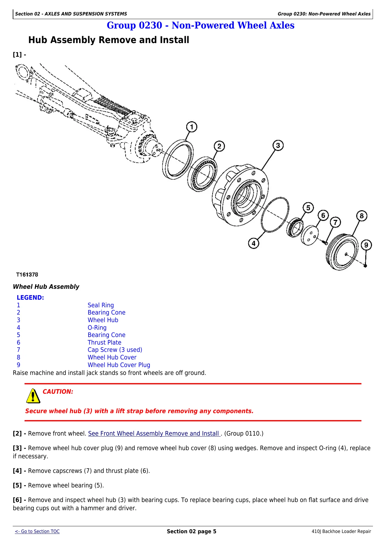
John Deere 410J Backhoe Loader Repair Technical Manual TM10851 - PDF Download — PDF page 70 preview
John Deere 410J Backhoe Loader Repair Technical Manual TM10851 - PDF Download — PDF page 92 preview

Engines Covered in This Manual

The engine removal and installation group covers the John Deere PowerTech and PowerTech E 4.5 L and 6.8 L engines as installed in the 410J, including the Stage II variant. The manual references the base engine and electronic fuel system component technical manuals (CTM104, CTM502, CTM331) for internal engine work, but the removal and installation procedures, mounting hardware, torque values, and the accessory layout around the engine are all contained here. Cold weather starting aid, cooling system, air intake, exhaust, and external fuel supply are covered as their own engine auxiliary groups so you can service the systems around the engine without leaving this document.

What This Manual Enables You to Do

With the John Deere 410J backhoe loader repair technical manual TM10851 open on your shop tablet or printed pages, you can remove and install the engine and torque converter, split and rebuild the transmission and its directional, speed, MFWD, and reverse clutch packs, service the PowerTech engine auxiliary systems, repair the front and rear axles, disassemble the differentials, replace service brake disks and park brake components, rebuild the steering valve and the steering cylinders for both non-powered and MFWD axles, service the loader and backhoe hydraulic circuits, reseal backhoe control valve sections, and repair the pilot control, pattern select, and ride control systems. Loader and backhoe frame and cylinder work, bucket and cutting edge replacement, plus the dealer fabricated tools needed for the larger lifts, are all documented with the same level of detail. The specs and wear tolerances printed here are what separate a repair that lasts from one that comes back; using the correct clearance on a clutch pack, the correct shim behind a pinion bearing, or the correct torque on a hydraulic fitting is the difference between a machine that goes back to work and one that leaks, whines, or fails again. This is an instantly downloadable PDF — no shipping, no waiting, readable on any phone, tablet, laptop, or desktop, and printable at whatever pages you need in the shop.
Reviews

There are no reviews yet.

Be the first to review “John Deere 410J Backhoe Loader Repair Technical Manual TM10851 – PDF Download”

What Our Customers Say

★★★★★ Live reviews from customers
Loading customer reviews...
0
    0
    Your Cart
    Your cart is emptyReturn to Shop
    🛒
    Recently Purchased
    🕒 verified order