★ TRUSTED BY 321,897+ PROFESSIONALS WORLDWIDE
🏒
Trusted Business
Verified & Licensed
πŸ›‘οΈ
Virus Free Files
100% Safe Downloads
πŸ”’
Secure Payment
SSL Protected
⚑
Instant Delivery
Available Immediately
Sale!

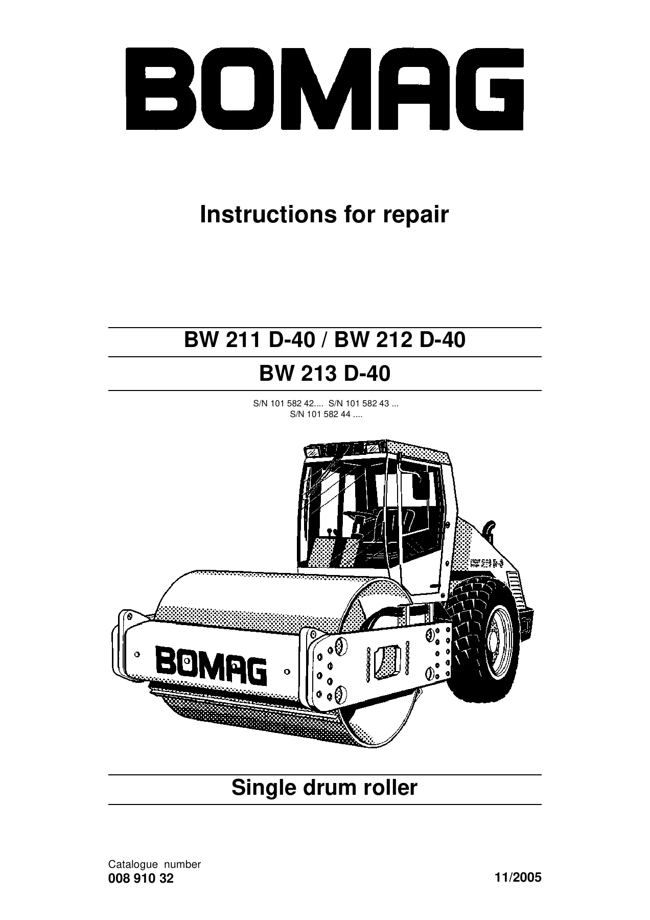
BOMAG BW 211 D-40 BW 212 D-40 BW 213 D-40 Single Drum Roller Repair Instructions PDF

Original price was: $39.95.Current price is: $23.95.

Complete BOMAG repair instructions for BW 211 D-40, BW 212 D-40 and BW 213 D-40 single drum rollers. 834 pages covering hydraulic travel and vibration circuits, drum overhaul, articulated joint, Deutz BF4M 2012 C engine, air conditioning, electrics and full circuit diagrams. Document 008 910 32.

⚑
Instant PDF Download
Available immediately
πŸ’Ύ
Save to Your Device
Download & keep forever
πŸ›‘οΈ
Antivirus Scanned
100% virus-free
🌍
Trusted Worldwide
175,000+ customers

Description

BOMAG BW 211 D-40 / BW 212 D-40 / BW 213 D-40 Repair Instructions

This is the full BOMAG repair instructions document (publication 008 910 32) for the BW 211 D-40, BW 212 D-40 and BW 213 D-40 single drum rollers. It is a workshop-level service manual written for the technician who has to take the machine apart, measure it, adjust it and put it back together correctly β€” not a quick-reference booklet. Across 834 pages it covers the Deutz BF4M 2012 C diesel engine, the hydrostatic travel circuit, the two-frequency vibration system, the drum assembly, the oscillating articulated joint, the air conditioning system and the complete machine electrics, plus full wiring and hydraulic circuit diagrams.

The BOMAG BW 211 D-40, BW 212 D-40 and BW 213 D-40 share the same repair instructions document because they share the same drive and vibration architecture. That makes this manual useful for the whole D-40 family, whether you are working on a 9.5 t BW 211, a 10.9 t BW 212 or a 12.4 t BW 213.

File Details

  • Manual type: Repair Instructions (workshop service manual)
  • Brand: BOMAG
  • Models covered: BW 211 D-40, BW 212 D-40, BW 213 D-40
  • Document number: 008 910 32
  • Language: English (with German section headers preserved, e.g. Technische Daten, Stromlaufplan)
  • File format: PDF
  • Page count: 834 pages

Chapters Covered

  • 1 General β€” Foreword, safety regulations, general repair instructions, tightening torques (metric coarse and fine thread), connection overview, technical data, table of fuels and lubricants
  • 2 Tests and adjustments β€” Special tools, solenoid adjustment for engine speed control, checking rotation speeds, neutral position of the travel pump, pressure tests in the travel circuit, vibrator shaft speeds, pressure measurements in the vibration circuit, leakage rate of the vibration motor, pressure test in the steering circuit
  • 3 Flushing and bleeding β€” Special tools for flushing, general flushing, flushing schematics and procedures for the travel circuit (travel pump and axle motor distribution) and the vibration drive, bleeding the travel circuit, bleeding the vibration circuit
  • 4 Technical Manual β€” Basic electrics (voltage, current, resistance, CAN, metrology, diodes, relays, fuses, battery, three-phase generator, starter, plugs, terminals), Service Training (Deutz engine, travel system, vibration, steering, electrics), Speedometer Module, Vibration module
  • 5 Air conditioning system β€” Safety notes, physical basics, refrigerant R134a, compressor oil, refrigeration diagram, component descriptions, compressor oil level, magnetic clutch, refrigerant circuit pressures, V-belt, servicing, drying and evacuation, leak test, filling instructions, heating and air conditioning control
  • 6 Replacing the cab window panes β€” Assembly of window panes, special tools, auxiliary materials, removing and installing the window pane
  • 7 Drum β€” Special tools, repair overview, removing and installing the drum, repairing the drum, disassembling and assembling the change-over weight, changing the rubber buffers and adjusting the pretension
  • 8 Oscillating articulated joint β€” Special tools, repair overview, removing and installing, dismantling, assembling
  • 9 Suppliers documentation β€” Travel pump series 90R, travel drive series 51, vibration pump 42R 041, vibration motor A10FM, MS/MSE 02 to 18, axle DANA 192
  • 10 Circuit diagrams β€” Wiring diagram (BW 177..219 D-4/D-40) and hydraulic diagram

What this document actually gives a technician is the full teardown and rebuild logic of the machine. Travel pump neutral is set with pressure gauges on ports MA and MB; charge pressure is checked on the same ports; the multi-function valves, high pressure relief valves and charge pressure relief valve are all identified by location and function. Vibration is handled in the same way β€” the vibration pump, high pressure relief valves, charge pump, vibration motor and drum are pulled apart in order, with tightening torques, clearances and adjustment values printed inline. The drum chapter walks through both exciter units (travel motor side and vibration motor side), the change-over weight, the rubber buffers and pretension setting. The articulated joint chapter includes shim thickness calculations and rocker bearing pressing procedures. Electrics runs from basic Ohm’s law and CAN through the wiring diagram, sensor testing, relay references and terminal block numbering. The final section reproduces the original equipment manufacturer documentation for the Sauer-Danfoss / Brueninghaus Hydromatik travel pump 90R075, travel drive 51D110, vibration pump 42R041, vibration motor A10FM45, Poclain MS/MSE motors and the DANA 192 axle.

Covered Machines and Serial Ranges

The BW 211 D-40 is listed with an operating weight of 9500 kg (CECE) and a static linear load of 27 kg/cm. The BW 212 D-40 raises that to 10900 kg / 11350 kg with ROPS and cabin, and 33.6 kg/cm static linear load. The BW 213 D-40 tops the range at 12420 kg / 12870 kg with ROPS and cabin, 36.7 kg/cm static linear load. All three share the same 98 kW Deutz BF4M 2012 C, a 2300 rpm rated speed, 60 litre hydraulic oil capacity, and the same 90R075 travel pump with a 51D110 axle motor and MSE 18 drum drive.

Serial numbers listed in the document are 101 582 42…, 101 582 43… and 101 582 44…, plus the corresponding 1001 series.

What Makes This Manual Different from a Generic Service Book

The material here is written around measurements and pressure readings, not around descriptions. Travel pump neutral is not “adjust until it feels right” β€” it is “connect 600 bar gauges to MA and MB, both must read charge pressure, if pressure builds on one side adjust the mechanical neutral until they match”. Vibration motor leakage is not described in vague terms β€” you disconnect the leak oil hose, hold a measuring hose in a beaker, run the vibration for one timed minute, and the permissible leak oil rate is 1.5 litre/min. The flushing procedures are split into two flow patterns because the flushing filter must sit on the low-pressure return side; the manual makes it clear that on a travel pump distribution setup the travel lever must be shifted forward only, otherwise the filter is fed from the wrong direction.

The drum chapter includes the change-over weight oil fill (2.5 litres of silicone oil 47 V 1000 cst up to the upper edge of the change-over weight), the Loctite grades used on specific fasteners, and the axial clearance check on the shaft after assembly. The articulated joint chapter includes the friction bearing assembly, the rocker bearing races, the V-ring and seal ring placement, and the shim thickness calculation that depends on an axial preload measurement.

The technical data chapter gives you the numbers you actually need for the machine: valve clearance 0.3 mm inlet / 0.5 mm outlet, injection valve opening pressure 220 bar, travel pump max displacement 75 cmΒ³/U with a 400 +26 bar high pressure limitation, charge pressure 26 bar at high idle, vibration pump 41 cmΒ³/U with a 345 +26 bar starting pressure, vibration motor 45 cmΒ³/U at 30/35 Hz and 2/1 mm amplitude, steering pressure 175 +26 bar, engine coolant 16 litres, engine oil 10 litres, hydraulic oil 60 litres, rear axle 11 litres, wheel hubs 2.9 litres per side, AC refrigerant 1300 g R134a and 100 ml PAG oil. Being able to read those values out of the same document that tells you how to pull the component apart is what separates a repair from an experiment.

Who This Is For

Heavy equipment mechanics, BOMAG service technicians, dealer workshops, rental fleet maintenance crews and owner-operators who do their own major repairs on the D-40 single drum rollers. The electrical and hydraulic diagrams are complete enough to be used as a fault-finding tool on their own, even if you are not pulling a component.

Get Instant Access to the Full BOMAG BW 211 / 212 / 213 D-40 Repair Instructions

With this BOMAG BW 211 D-40 BW 212 D-40 BW 213 D-40 repair instructions PDF on hand you can diagnose charge pressure drops, chase travel pump neutral faults, measure vibration motor leakage, rebuild the drum exciter units, replace the oscillating articulated joint bearings, service the air conditioning system and trace electrical faults against the original wiring diagram. Every procedure gives you the correct sequence, the correct tightening torque, the correct pressure or clearance to aim for, and the correct way to bleed and flush the circuit afterwards β€” which is exactly what prevents the second failure that comes from skipping a step.

Complete PDF Bookmark Tree

Complete Bookmarks

The complete bookmarks in the β€œBOMAG BW 211 D-40 BW 212 D-40 BW 213 D-40 Single Drum Roller Repair Instructions PDF” are as follows:

BW 211 D-40 / BW 212 D-40p. 1
BW 213 D-40p. 1
S/N 101 582 42…. S/N 101 582 43 …p. 1
S/N 101 582 44 ….p. 1
Single drum rollerp. 1
1 Generalp. 5
Forewordp. 6
Introductionp. 6
Safety regulationsp. 7
Important notesp. 7
Generalp. 7
Special safety regulationsp. 7
Hydraulicsp. 8
Air conditioning systemp. 8
General repair instructionsp. 10
Generalp. 10
Hydraulic systemp. 10
Seals and gasketsp. 10
Air conditioning systemp. 11
Electricsp. 12
Tightening torquesp. 13
Connection overview
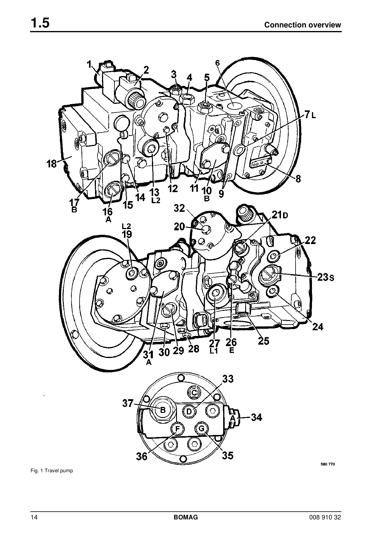
Fig. 1 Travel pumpp. 14
Technische Daten
Fig. 2p. 20
BW 211 D-40p. 20
BW 211 PD-40p. 20
BW 211 D-40p. 20
BW 211 PD-40p. 20
Weightsp. 20
Travel characteristicsp. 20
Enginep. 20
Brakesp. 21
Steeringp. 21
Vibrationp. 21
Tiresp. 21
Filling capacitiesp. 21
Fig. 3p. 22
BW 212 D-40p. 22
BW 212 PD-40p. 22
BW 212 D-40p. 22
BW 212 PD-40p. 22
Weightsp. 22
Travel characteristicsp. 22
Enginep. 22
Brakesp. 23
Steeringp. 23
Vibrationp. 23
Tiresp. 23
Filling capacitiesp. 23
Fig. 4p. 24
BW 213 D-40p. 24
BW 213 PD-40p. 24
BW 213 D-40p. 24
BW 213 PD-40p. 24
Weightsp. 24
Travel characteristicsp. 24
Enginep. 24
Brakesp. 25
Steeringp. 25
Vibrationp. 25
Tiresp. 25
Filling capacitiesp. 25
1.7 Table of fuels and lubricantsp. 26
Assemblyp. 26
Fuel or lubricantp. 26
Quantity approx.p. 26
Summerp. 26
Winterp. 26
2 Tests and adjustmentsp. 27
2.1 Special tools, tests and adjustmentsp. 28
Fig. 1p. 28
Fig. 2p. 28
Fig. 3p. 28
Fig. 4p. 28
Fig. 5p. 29
Fig. 6p. 29
Fig. 7p. 29
Fig. 8p. 29
Fig. 9p. 30
Fig. 10p. 30
2.2 Adjusting the solenoid for engine speed controlp. 31
Fig. 1p. 31
2.3 Checking the rotation speedsp. 32
Fig. 1p. 32
Check the engine speedp. 32
Fig. 2p. 32
Checking the exciter shaft speedp. 33
Fig. 3p. 33
2.4 Checking / adjusting the neutral positions of the travel pumpp. 34
Fig. 1p. 34
Fig. 2p. 34
Fig. 3p. 34
Fig. 4p. 35
Fig. 5p. 35
Fig. 6p. 35
Fig. 7p. 35
2.5 Pressure tests in the travel circuitp. 36
Fig. 1p. 36
Fig. 2p. 36
Fig. 3p. 36
Fig. 4p. 37
2.6 Checking / adjusting the vibrator shaft speedsp. 38
Fig. 1p. 38
Fig. 2p. 38
Fig. 3p. 38
2.7 Pressure measurements in the vibration circuitp. 39
Fig. 1p. 39
Fig. 2p. 39
2.8 Check the leakage rate of the vibration motorp. 40
Fig. 1p. 40
Fig. 2p. 40
Fig. 3p. 40
2.9 Pressure test in steering circuitp. 41
Fig. 1p. 41
Fig. 2p. 41
Fig. 3p. 41
Fig. 4p. 42
Fig. 5p. 42
3 Flushing and bleedingp. 43
3.1 Special tools for flushingp. 44
Fig. 1p. 44
Fig. 2p. 44
Fig. 3p. 44
Fig. 4p. 44
Fig. 5p. 45
Fig. 6p. 45
Fig. 7p. 45
Fig. 8p. 45
Fig. 9p. 46
Fig. 10p. 46
Fig. 11p. 46
Fig. 12p. 46
Fig. 13p. 47
Fig. 14p. 47
Fig. 15p. 47
3.2 Flushing – generalp. 48
Changing a componentp. 48
Chips (abrasion) in the oilp. 48
Before flushingp. 48
Fig. 1p. 48
Fig. 2p. 48
Fig. 3p. 48
Bleedingp. 49
Fig. 4p. 49
Servicing the flushing filter kitp. 49
Fig. 5p. 49
3.3 Flushing schematic travel circuit (distribution travel pump)p. 50
3.4 Flushing the travel circuit (travel pump distribution)p. 52
Flushing the drum drivep. 52
Fig. 1p. 52
Fig. 2p. 52
Fig. 3p. 53
Fig. 4p. 53
Fig. 5p. 53
Fig. 6p. 53
Fig. 7p. 54
Fig. 8p. 54
Fig. 9p. 54
Flushing the axle drivep. 55
Fig. 10p. 55
Fig. 11p. 55
Fig. 12p. 55
Fig. 13p. 56
Fig. 14p. 56
Fig. 15p. 56
Fig. 16p. 56
Fig. 17p. 57
Fig. 18p. 57
Fig. 19p. 57
3.5 Flushing schematic travel circuit (distribution axle motor)p. 58
3.6 Flushing the travel circuit (axle motor distribution)p. 63
Flushing the drum drivep. 63
Fig. 1p. 63
Fig. 2p. 63
Fig. 3p. 64
Fig. 4p. 64
Fig. 5p. 64
Fig. 6p. 64
Fig. 7p. 65
Fig. 8p. 65
Fig. 9p. 65
Flushing the axle motorp. 66
Fig. 10p. 66
Fig. 11p. 66
Fig. 12p. 66
Fig. 13p. 67
3.7 Flushing schematic for vibration drivep. 68
3.8 Flushing the vibration circuitp. 70
Fig. 1p. 70
Fig. 2p. 70
Fig. 3p. 71
Fig. 4p. 71
Fig. 5p. 71
Fig. 6p. 71
Fig. 7p. 72
Fig. 8p. 72
Fig. 9p. 72
Fig. 10p. 73
3.9 Bleeding the travel circuitp. 74
Fig. 1p. 74
Fig. 2p. 74
Fig. 3p. 74
Fig. 4p. 75
Fig. 5p. 75
3.10 Bleeding the vibration circuitp. 76
Fig. 1p. 76
Fig. 2p. 76
Fig. 3p. 76
Fig. 4p. 77
Fig. 5p. 77
4 Technical Manualp. 79
4.1 Technical Manual / Basic Electricsp. 81
4.2 Techn.Manual/Service Trainingp. 133
4.3 Speedometer Modulep. 249
4.4 Vibration modulep. 253
5 Air conditioning systemp. 257
5.1 Notes on safety for the air conditioning systemp. 258
Air conditioning systemp. 258
5.2 Notes on repair of the air conditioning systemp. 259
Air conditioning systemp. 259
Physical basicsp. 261
Fig. 1p. 261
Fig. 2p. 261
Pressure and boiling pointp. 262
Fig. 3p. 262
Fig. 4p. 262
5.4 Refrigerant R134ap. 263
Environmental aspectsp. 264
5.5 Compressor oil / refrigeration oilp. 264
5.6 Working principle of the air conditioning systemp. 265
Fig. 1p. 265
5.7 Refrigeration diagramp. 266
Fig. 1p. 266
5.8 Description of componentsp. 267
Compressorp. 267
Fig. 1p. 267
Condenserp. 268
Fig. 1p. 268
Dryer / filter / fluid container / inspection glassp. 268
Fig. 1p. 268
Fig. 2p. 269
Fig. 3p. 269
Expansion valvep. 270
Fig. 1p. 270
Evaporatorp. 270
Fig. 1p. 270
Defroster thermostatp. 271
Fig. 1p. 271
Pressure switchp. 271
Fig. 1p. 271
Pipes and hosesp. 272
Checking the compressor oil levelp. 273
Checking the compressor oil level / refrigeration oil levelp. 273
Fig. 1p. 273
Fig. 2p. 273
5.10 Checking the magnetic clutchp. 274
Fig. 1p. 274
Fig. 2p. 274
5.11 Inspection and maintenance workp. 275
5.12 Measuring the pressure in the refrigerant circuitp. 275
Fig. 3p. 275
The pressure in the refrigerant circuit is lower than the value in the tablep. 276
5.13 Checking, replacing the refrigerant compressor V-beltp. 276
Check the V-beltp. 276
Fig. 4p. 276
Tighten the V-belt.p. 276
Fig. 5p. 276
Changing the V-beltp. 277
5.14 Servicing the air conditioningp. 277
Cleaning the condenserp. 277
Fig. 6p. 277
Checking the refrigerant levelp. 277
Fig. 7p. 278
Fig. 8p. 278
Fig. 9p. 278
Fig. 10p. 278
Checking the moisture level of the drying agentp. 278
Fig. 11p. 278
Checking the condition of the drier/collector unitp. 279
Fig. 12p. 279
5.15 Drying and evacuationp. 279
5.16 Emptying in case of repairp. 280
5.17 Leak testp. 280
5.18 Filling instructionsp. 281
Fig. 1p. 282
Filling instructionsp. 283
5.19 Heating control / air conditioning controlp. 285
6 Replacing the cab window panesp. 291
Assembly of window panes
Fig. 1p. 292
6.2 Special toolsp. 293
Fig. 1p. 293
Fig. 2p. 293
6.3 Auxiliary materialsp. 294
Fig. 1p. 294
Fig. 2p. 294
Fig. 3p. 294
Fig. 4p. 295
6.4 Removing and installing the window panep. 296
Fig. 1p. 296
Fig. 2p. 296
Fig. 3p. 296
Fig. 4p. 297
Fig. 5p. 297
Fig. 6p. 297
Fig. 7p. 297
Fig. 8p. 298
Fig. 9p. 298
Fig. 10p. 298
Fig. 11p. 298
Fig. 12p. 299
Fig. 13p. 299
Fig. 14p. 299
7 Drump. 301
7.1 Special toolsp. 302
Fig. 1p. 302
Fig. 2p. 302
Fig. 3p. 302
Fig. 4p. 302
Fig. 5p. 303
Fig. 6p. 303
Fig. 7p. 303
Repair overview for drum
7.3 Removing and installing the drump. 312
Fig. 1p. 312
Fig. 2p. 312
Removing the drump. 312
Fig. 3p. 312
Fig. 4p. 313
Fig. 5p. 313
Fig. 6p. 313
Fig. 7p. 313
Fig. 8p. 314
Fig. 9p. 314
Fig. 10p. 314
Fig. 11p. 314
Installing the drump. 315
Fig. 12p. 315
Fig. 13p. 315
Fig. 14p. 315
Fig. 15p. 315
Fig. 16p. 316
Fig. 17p. 316
Fig. 18p. 316
Fig. 19p. 316
7.4 Repairing the drump. 317
Removing the travel motorp. 317
Fig. 1p. 317
Fig. 2p. 317
Fig. 3p. 317
Fig. 4p. 318
Disassembling the exciter unit (travel motor side)p. 318
Fig. 5p. 318
Fig. 6p. 318
Fig. 7p. 319
Fig. 8p. 319
Disassembling the exciter unit (travel motor side)p. 319
Fig. 9p. 319
Fig. 10p. 320
Fig. 11p. 320
Fig. 12p. 320
Fig. 13p. 320
Fig. 14p. 321
Fig. 15p. 321
Fig. 16p. 321
Fig. 17p. 321
Fig. 18p. 322
Fig. 19p. 322
Fig. 20p. 322
Disassembling the exciter unit (vibration motor side)p. 323
Fig. 21p. 323
Fig. 22p. 323
Fig. 23p. 323
Fig. 24p. 324
Fig. 25p. 324
Fig. 26p. 324
Fig. 27p. 324
Fig. 28p. 325
Removing, dismantling the side platep. 325
Fig. 29p. 325
Fig. 30p. 325
Fig. 31p. 325
Fig. 32p. 326
Fig. 33p. 326
Fig. 34p. 326
Dismantling the exciter unit (vibration motor side)p. 327
Fig. 35p. 327
Fig. 36p. 327
Fig. 37p. 327
Fig. 38p. 328
Fig. 39p. 328
Fig. 40p. 328
Fig. 41p. 328
Fig. 42p. 329
Fig. 43p. 329
Fig. 44p. 329
Fig. 45p. 329
Assembling the exciter unit (vibration motor side)p. 330
Fig. 46p. 330
Fig. 47p. 330
Fig. 48p. 330
Fig. 49p. 331
Fig. 50p. 331
Fig. 51p. 331
Fig. 52p. 331
Fig. 53p. 332
Fig. 54p. 332
Fig. 55p. 332
Fig. 56p. 332
Fig. 57p. 333
Fig. 58p. 333
Fig. 59p. 333
Fig. 60p. 333
Fig. 61p. 334
Fig. 62p. 334
Fig. 63p. 334
Fig. 64p. 334
Fig. 65p. 335
Fig. 66p. 335
Fig. 67p. 335
Assembling and installing the side platep. 336
Fig. 68p. 336
Fig. 69p. 336
Fig. 70p. 336
Fig. 71p. 337
Fig. 72p. 337
Fig. 73p. 337
Fig. 74p. 337
Fig. 75p. 338
Fig. 76p. 338
Fig. 77p. 338
Fig. 78p. 338
Fig. 79p. 339
Assembling the exciter unit (travel motor side)p. 339
Fig. 80p. 339
Fig. 81p. 339
Fig. 82p. 340
Fig. 83p. 340
Fig. 84p. 340
Fig. 85p. 340
Fig. 86p. 341
Fig. 87p. 341
Fig. 88p. 341
Fig. 89p. 341
Fig. 90p. 342
Fig. 91p. 342
Fig. 92p. 342
Fig. 93p. 342
Fig. 94p. 343
Fig. 95p. 343
Fig. 96p. 343
Fig. 97p. 343
Assembling the exciter unit (travel motor side)p. 344
Fig. 98p. 344
Fig. 99p. 344
Fig. 100p. 344
Fig. 101p. 345
Fig. 102p. 345
Installing the travel motorp. 345
Fig. 103p. 345
Fig. 104p. 345
Fig. 105p. 346
Fig. 106p. 346
Installing the exciter unit (vibration motor side)p. 346
Fig. 107p. 346
Fig. 108p. 347
Fig. 109p. 347
Fig. 110p. 347
Fig. 111p. 347
Fig. 112p. 348
Fig. 113p. 348
Fig. 114p. 348
Fig. 115p. 348
Fig. 116p. 349
Fig. 117p. 349
7.5 Disassembling and assembling the change-over weightp. 350
Dismantling the change-over weightp. 350
Fig. 1p. 350
Fig. 2p. 350
Fig. 3p. 350
Fig. 4p. 351
Assembling the change-over weightp. 351
Fig. 5p. 351
Fig. 6p. 351
Fig. 7p. 351
Fig. 8p. 352
7.6 Changing the rubber buffers and adjusting the pretensionp. 353
Fig. 1p. 353
Fig. 2p. 353
Fig. 3p. 353
Fig. 4p. 354
Fig. 5p. 354
Fig. 6p. 354
Fig. 7p. 354
Fig. 8p. 355
Fig. 9p. 355
Fig. 10p. 355
8 Oscillating articulated jointp. 357
8.1 Special toolsp. 358
Fig. 1p. 358
Fig. 2p. 358
Fig. 3p. 358
Fig. 4p. 358
Fig. 5p. 359
Fig. 6p. 359
Repair overview oscillating articulated joint
8.3 Removing and installing the oscillating articulated jointp. 363
Fig. 1p. 363
Fig. 2p. 363
Fig. 3p. 363
Fig. 4p. 364
Fig. 5p. 364
Fig. 6p. 364
Fig. 7p. 364
8.4 Dismantling the oscillating articulated jointp. 365
Fig. 1p. 365
Fig. 2p. 365
Fig. 3p. 365
Fig. 4p. 366
Fig. 5p. 366
Fig. 6p. 366
Fig. 7p. 366
Fig. 8p. 367
Fig. 9p. 367
Fig. 10p. 367
Fig. 11p. 367
Fig. 12p. 368
Fig. 13p. 368
Fig. 14p. 368
Fig. 15p. 368
Fig. 16p. 369
8.5 Assembling the oscillating articulated jointp. 370
Fig. 1p. 370
Fig. 2p. 370
Fig. 3p. 370
Fig. 4p. 371
Fig. 5p. 371
Fig. 6p. 371
Fig. 7p. 371
Fig. 8p. 372
Fig. 9p. 372
Fig. 10p. 372
Fig. 11p. 372
Fig. 12p. 373
Fig. 13p. 373
Fig. 14p. 374
Fig. 15p. 374
Fig. 16p. 374
Fig. 17p. 374
Fig. 18p. 375
Fig. 19p. 375
Fig. 20p. 375
Fig. 21p. 375
Fig. 22p. 376
Fig. 23p. 376
Fig. 24p. 376
Fig. 25p. 376
Fig. 26p. 377
Fig. 27p. 377
Fig. 28p. 377
Fig. 29p. 378
Fig. 30p. 378
Fig. 31p. 378
Fig. 32p. 378
Fig. 33p. 379
9 Suppliers documentationp. 381
9.1 Travel pump series 90Rp. 383
9.2 Travel drive series 51p. 473
9.3 Vibration pump 42R 041p. 555
9.4 Vibration motor A10FMp. 593
9.5 MS/MSE 02 to 18p. 617
9.6 Axle DANA 192p. 667
10 Circuit diagramsp. 791
Circuit diagramsp. 792
10.1 Wiring diagramp. 793
10.2 Hydraulic diagramp. 829


IMAGES PREVIEW

BOMAG BW 211 D-40 BW 212 D-40 BW 213 D-40 Single Drum Roller Repair Instructions PDF β€” PDF page 1 preview
BOMAG BW 211 D-40 BW 212 D-40 BW 213 D-40 Single Drum Roller Repair Instructions PDF β€” PDF page 14 preview
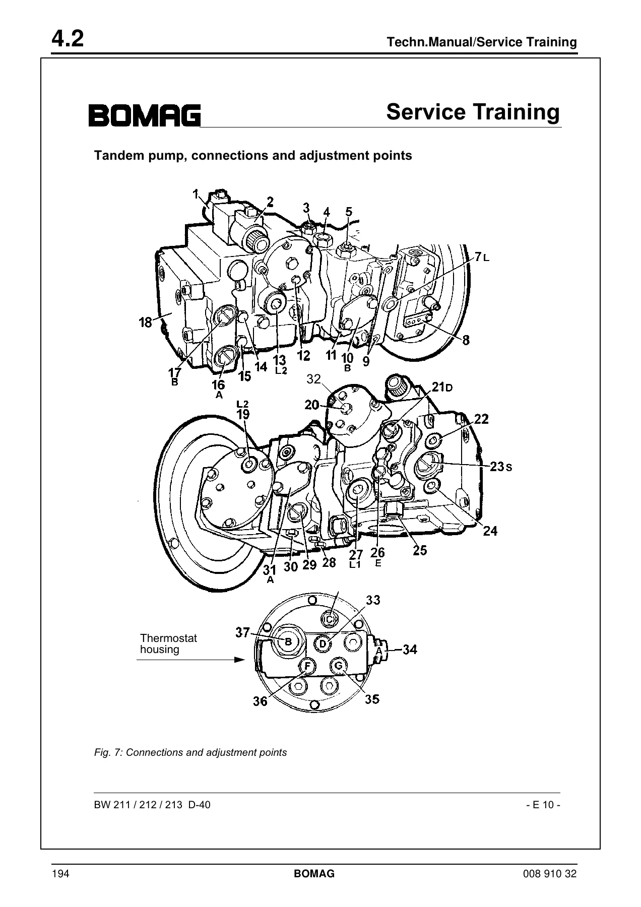
BOMAG BW 211 D-40 BW 212 D-40 BW 213 D-40 Single Drum Roller Repair Instructions PDF β€” PDF page 194 preview

Delivery is instant. The file downloads as a PDF immediately after payment and can be opened on a laptop, tablet or phone in the workshop, or printed out for the pages you need on the bench. No shipping, no waiting, no separate parts catalogue required to follow the assembly order.


Reviews

There are no reviews yet.

Be the first to review “BOMAG BW 211 D-40 BW 212 D-40 BW 213 D-40 Single Drum Roller Repair Instructions PDF”

What Our Customers Say

β˜…β˜…β˜…β˜…β˜… Live reviews from customers
Loading customer reviews...
0
    0
    Your Cart
    Your cart is emptyReturn to Shop
    πŸ›’
    Recently Purchased
    πŸ•’ verified order