
John Deere 410J Backhoe Loader Repair Technical Manual TM10147 – PDF Download
Original price was: $59.95.$39.95Current price is: $39.95.
Complete John Deere 410J Backhoe Loader Repair Technical Manual (TM10147, 08JUN07). 720-page English PDF covering engine, transmission, axles, hydraulics, loader and backhoe repair procedures, torque values and specifications.
Description
John Deere 410J Backhoe Loader Repair Technical Manual — TM10147
This is the complete John Deere 410J Backhoe Loader Repair Technical Manual, published under document number TM10147 and dated 08JUN07. It is the repair-side technical manual prepared by John Deere for experienced technicians working on the 410J backhoe loader, and it carries component-level service information for the entire machine. Rather than a general owner’s guide, this is a bench-and-shop manual: each group opens with a summary listing of the applicable essential tools, service equipment, materials, service parts kits, specifications, wear tolerances and torque values, followed by the step-by-step removal, installation, disassembly and assembly procedures. Engine coverage centres on the POWERTECH 4.5L (4045) and 6.8L (6068) John Deere diesel engines.
File Details
- Manual type: Repair Technical Manual
- Brand: John Deere
- Model: 410J Backhoe Loader
- Engines covered: POWERTECH 4.5L (4045) and 6.8L (6068) John Deere diesel engines
- Language: English
- Page count: 720
- File format: PDF
- Document number: TM10147
- Publication date: 08JUN07
Chapters Covered
- Section 00 — General Information
- Section 01 — Wheels
- Section 02 — Axles and Suspension Systems
- Section 03 — Transmission
- Section 04 — Engine
- Section 05 — Engine Auxiliary Systems
- Section 06 — Torque Converter
- Section 09 — Steering System
- Section 10 — Service Brakes
- Section 11 — Park Brake
- Section 17 — Frame or Supporting Structure
- Section 18 — Operator’s Station
- Section 19 — Sheet Metal and Styling
- Section 20 — Safety, Convenience and Miscellaneous
- Section 21 — Main Hydraulic System
- Section 31 — Loader
- Section 33 — Backhoe
- Section 99 — Dealer Fabricated Tools
Section 00 — General Information
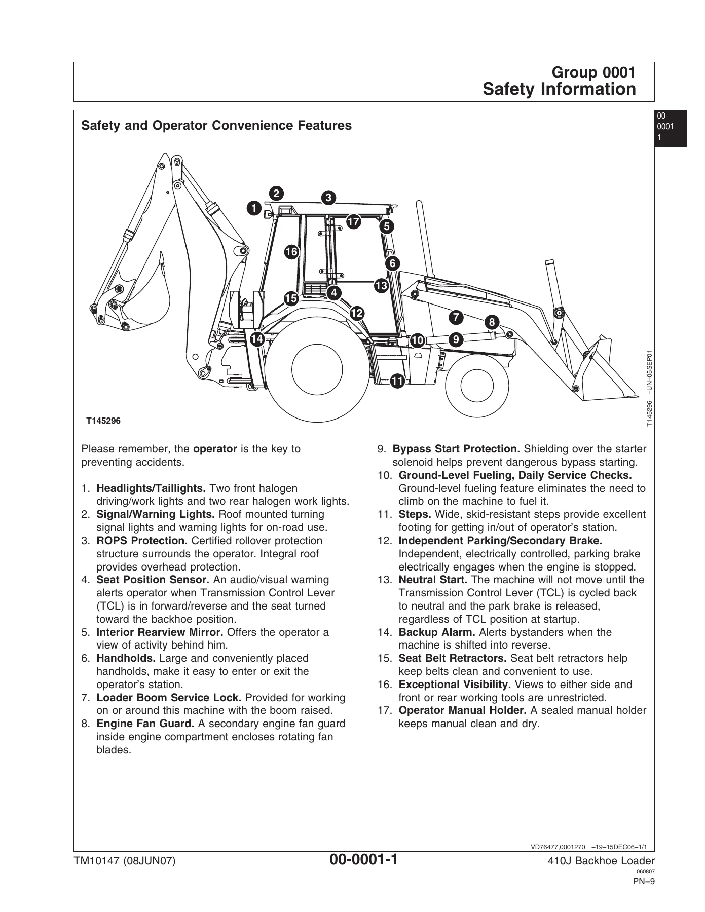
Safety information for the 410J is consolidated here, covering the safety-alert system, DANGER, WARNING and CAUTION signage, high-pressure fluid hazards, battery and fire precautions, ROPS inspection, and safe parking and service preparation. The torque-values group is the reference backbone for the whole manual: metric bolt and cap screw torque tables by property class (4.8, 8.8, 9.8, 10.9, 12.9), additional metric cap screw values, and unified inch bolt and cap screw torque tables by SAE grade. A long run of hydraulic fitting service recommendations is included for 37° flare and 30° cone seat connectors, O-ring boss fittings, O-ring boss fittings in aluminium housings, flared connections with straight or tapered threads, flat face O-ring seal fittings, O-ring face seal fittings with SAE inch and metric hex nuts for standard and high pressure, metric and inch four bolt flange fittings, non-restricted banjo fittings, O-ring boss fittings with shoulder, and metric 24° O-ring seal DIN 20078.
Sections 01 & 02 — Wheels, Axles and Suspension Systems
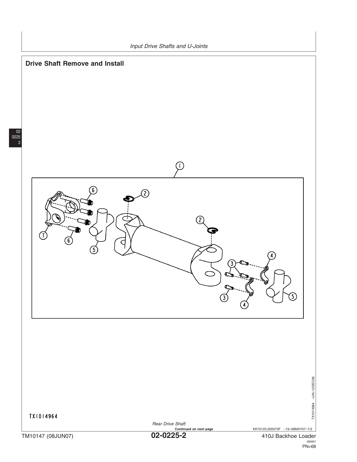
Rear wheel and front wheel assembly removal and installation is covered with the cap screw torque values for the 19.5L x 24 rear wheels and the 11L x 16 and 14.5/75-16.1 front wheel options, plus a tire remove and install procedure with the valve core, valve nut, soap lubricant and pressure-regulating valve safety steps. The axles group covers input drive shafts and U-joints, non-powered wheel axle hub and spindle assembly removal and installation, tie rod removal and installation, and non-powered front axle removal. For MFWD machines the mechanical front wheel drive axle is covered for removal, installation, disassembly and assembly, with cross-references to Front Wheel Drive Axles AS and MS Series CTM4687. The axle shaft, bearing and reduction gear group covers service brake inspection with disk clearance measurement (4.5 mm minimum disk thickness), rear axle removal, installation, full disassembly, park brake disassembly and assembly, rear axle assembly, and gear tooth contact pattern checking with the coast and drive side illustrations.
Section 03 — Transmission
Transmission removal and installation is documented with the low lift jack mounting, engine support bracket installation, torque converter flex plate cap screw removal and the transmission-to-flywheel housing cap screw torque. The controls linkage group covers the Transmission Control Lever (TCL) removal and installation. The gears, shafts and power shift clutches group is a deep teardown resource: removing outer components to disassemble the transmission, disassembling the torque converter side of the transmission case, clutch pack removal, transmission pump removal, disassembly and assembly, and individual disassembly and assembly procedures for the high range forward, low range forward, reverse, first speed, third speed, second speed and MFWD clutch packs. Pump drive shaft installation, clutch pack installation, transmission case assembly and outer component installation are all covered, followed by the hydraulic system charge pump removal, installation, disassembly and assembly.
Sections 04, 05 & 06 — Engine, Auxiliary Systems and Torque Converter
Engine removal and installation covers the POWERTECH 4.5L (4045) and 6.8L (6068) John Deere diesel engines, with cross-references to POWERTECH Base Engine CTM104 and Level 12 Electronic Fuel Systems with Stanadyne DE10 Pump CTM331. The auxiliary systems group covers cold weather starting aid components (coolant heater, starting aid nozzle, starting aid solenoid), cooling system service (fan, fan belt and radiator), engine speed control pedal, air cleaner, muffler with turbocharger, and fuel tank removal and installation. Torque converter removal, installation, disassembly and assembly is covered separately; the manual notes the torque converter has no internal service parts and is replaced as a unit if damaged.
Sections 09, 10 & 11 — Steering, Service Brakes and Park Brake
Steering coverage includes steering column removal and installation, standard and tilt steering wheel and column disassembly and assembly, steering valve removal, installation, disassembly and assembly (including the manual steering check ball, anti-cavitation balls, spool, sleeve, gerotor star and drive spline timing), non-powered front axle steering cylinder removal, installation, disassembly and assembly, and MFWD axle steering cylinder disassembly and assembly. Service brakes cover external inspection, brake disk and pressure plate removal and installation, brake valve removal, installation, disassembly and assembly with the piston, spring, push rod and adapter valve details, brake valve lines, brake pedal removal and installation, brake pedal adjustment and the brake system bleeding procedure. The park brake is covered through the rear axle group.
Sections 17, 18, 19 & 20 — Frame, Operator’s Station and Body
Frame coverage includes welding repair of major structures with the recommended AWS electrode processes and preheat temperatures, RIVNUT (KREMNUT) fastener removal and installation with the JDG894 tool and length selection chart, main frame bushing service, and counterweight removal and installation with primary and additional counterweight torque values. The operator’s station group is extensive: cab/ROPS removal and installation, front and rear window wiper and motor service, fixed and front windowpane removal and installation, cab door and side window disassembly and assembly, door hinge and latch adjustment, door handle screw adjustment, rear window removal and installation, headliner and cab roof. Seat and seat belt coverage includes seat assembly removal and installation, seat and arm rest disassembly, seat belt disassembly, seat slide, lumbar support and adjuster control levers, seat swivel and swivel latch, seat suspension and shock absorber, and the air suspension seat. Heating and air conditioning covers R134a handling, refrigerant hose and tubing inspection, compressor removal and installation, compressor disassembly and assembly, clutch disassembly and assembly, clutch hub clearance check, manifold inspection, compressor oil removal, component oil charge, recover, recycle and charge station installation, recover, evacuate, charge, cleaning, leak testing, flush and purge procedures, heater core, evaporator, freeze switch, heater/blower assembly, air ducts, condenser, receiver dryer and expansion valve. Sheet metal covers the hood and engine enclosure, battery box, grille and grille housing, and fenders and cab skirts.
Sections 21, 31, 33 & 99 — Main Hydraulic System, Loader, Backhoe and Dealer Tools
The main hydraulic system group covers hydraulic pump removal and installation, hydraulic pump disassembly and assembly (noting that internal pump and rotate group components are serviced as an assembly), hydraulic pump control disassembly and assembly, power limiting valve removal and installation, hydraulic filter assembly, hydraulic reservoir removal, installation, disassembly and assembly, and the hydraulic and transmission oil coolers. Loader coverage includes boom removal and installation, bucket and cutting edge removal and installation, cutting edge crack repair, multi-purpose bucket and lines, attachment coupler and coupler cylinder, loader control valve linkage, third function loader control valve linkage, stabilizer linkage, loader bucket linkage, loader and stabilizer control valve removal, installation, disassembly and assembly, relief valves, load sense relief valve, boom raise and bucket curl circuit relief valve, bucket dump circuit relief valve with anti-cavitation, anti-cavitation valve, auxiliary circuit relief valve, auxiliary shutoff plug, bucket cylinder, boom cylinder, ride control valve, ride control valve solenoid and ride control accumulator. Backhoe coverage includes bucket and bucket links, tooth tips, tooth shank, cutting edge, control valve linkage two and three lever, fifth and sixth function pedals, pilot control valve, pilot control tower, boom lock control lever and linkage, boom lock, dipperstick, boom, swing frame, extendible dipperstick extension, control valve removal and installation, control valve disassembly and assembly, spool seals, relief valves, inlet, flow control, swing, boom, bucket, crowd, extendible dipperstick and outlet sections, pilot control manifold valve, pattern select valve, and the bucket, crowd, boom, swing, stabilizer and extendible dipperstick cylinders. The dealer fabricated tools group provides drawings and materials lists for the DFRW20 compressor holding fixture, DFT1101 cab and ROPS lift bracket, DFT1285 engine support bracket and DFT1286 backlash measurement tool.
Why This 410J Repair Manual Belongs in Your Shop
IMAGES PREVIEW
Owning the John Deere 410J Backhoe Loader Repair Technical Manual TM10147 means you are working from the same component-level procedures, tolerances and torque values the machine was designed around. Every job a 410J is likely to need is here: engine removal and installation, transmission and clutch pack teardown, rear axle and service brake disassembly, park brake assembly, MFWD axle service, steering valve and steering cylinder repair, hydraulic pump and pump control service, power limiting valve replacement, loader and stabilizer control valve overhaul, backhoe control valve section teardown, and the full run of backhoe, loader, swing, stabilizer and extendible dipperstick cylinders. Instead of guessing at clearances, snap ring thicknesses, shim packs, bearing temperatures, rolling torque figures and preload values, you can follow the documented inspection limits and wear tolerances the manual sets out, order the right service parts kits and special tools, and reassemble to specification the first time. The manual also includes the dealer-fabricated tool drawings so you can build or borrow the correct supports, brackets, lift points and measurement tools before you start. This PDF is delivered instantly after purchase — no shipping, no waiting. Download it once and keep it on the shop laptop, tablet or phone, or print the section you need for the job at hand. The John Deere 410J Backhoe Loader Repair Technical Manual TM10147 is the reference you reach for before the first bolt comes out, and the one you keep on the bench until the machine is back in service.
Reviews
There are no reviews yet.