
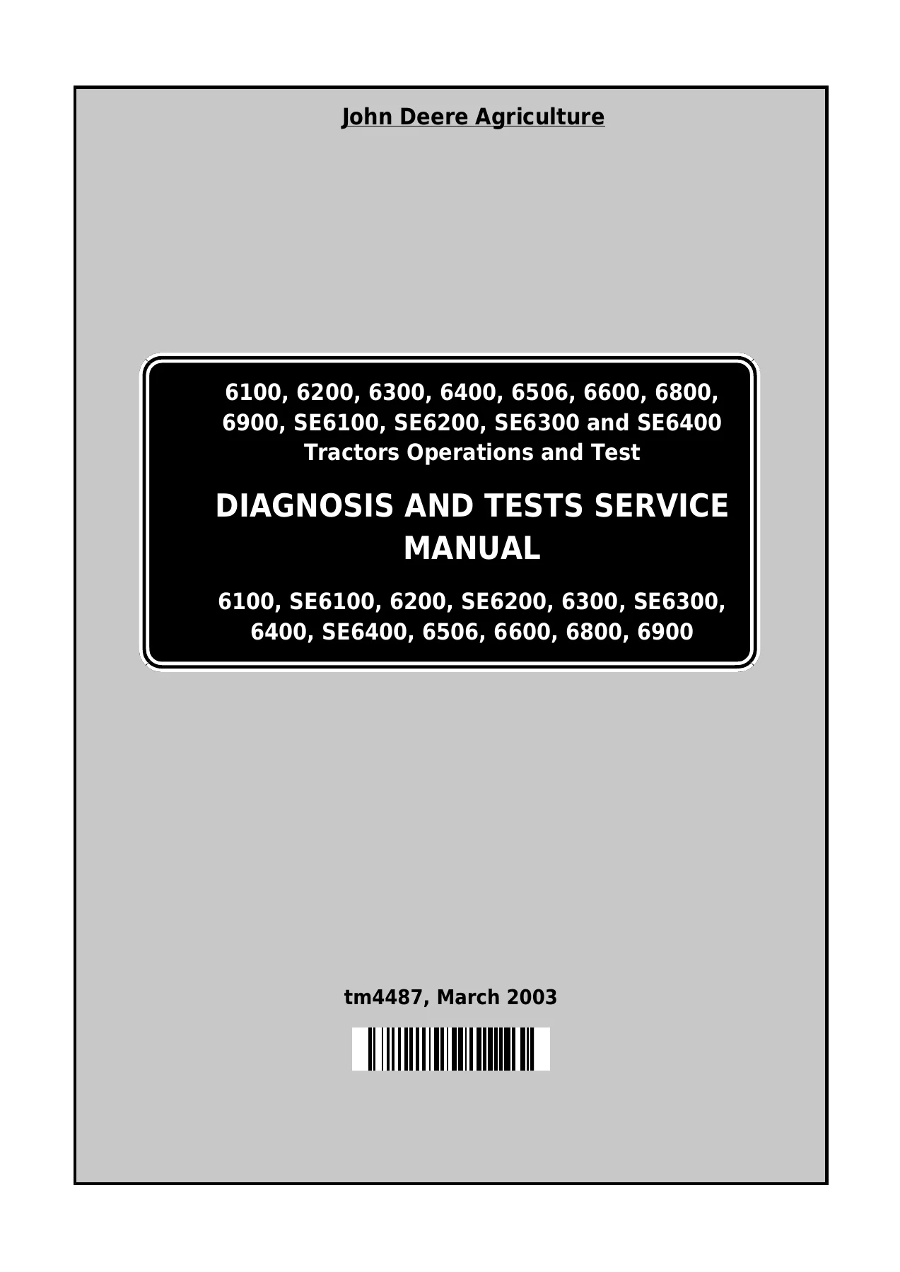
John Deere 6100-6900 & SE Tractors Diagnosis and Tests Service Manual TM4487 (2003) – PDF Download
Original price was: $63.95.$39.95Current price is: $39.95.
Complete John Deere TM4487 Diagnosis and Tests Service Manual covering 6100, 6200, 6300, 6400, 6506, 6600, 6800, 6900 and SE series tractors. Instant PDF download with full service code diagnostics, system tests, electrical schematics and hydraulic circuit diagrams.
Description
John Deere 6100-6900 & SE Tractors Diagnosis and Tests Service Manual TM4487
This complete John Deere 6100 6200 6300 6400 6506 6600 6800 6900 and SE Tractors Diagnosis and Tests Service Manual is the diagnostic reference for technicians working on these machines. Published in 2003 as document TM4487, it covers service code retrieval, system tests, pressure and flow checks, electrical schematics and hydraulic circuit diagrams across all the listed models and their SE equivalents. Every procedure is written for the shop floor — from pulling HCU, BCU and RCU fault codes through to dynamometer testing, transmission pressure checks and hitch calibration.
File Details
- Manual type: Diagnosis and Tests Service Manual
- Brand: John Deere
- Models covered: 6100, 6200, 6300, 6400, 6506, 6600, 6800, 6900, SE6100, SE6200, SE6300, SE6400
- Document number: TM4487
- Date: 2003
- Language: English
- Format: PDF
- Pages: 3004
Chapters Covered
- Section 210 — Safety
- Section 211 — Service Codes
- Section 212 — Observable Symptom
- Section 220 — Engine
- Section 230 — Fuel, Air Intake and Cooling Systems
- Section 240 — Electrical System
- Section 250 — SyncroPlus Transmission
- Section 251 — PowrReverser
- Section 255 — PowrQuad Transmission
- Section 256 — Drive Systems
- Section 260 — Steering and Brakes
- Section 270 — Hydraulic System
- Section 290 — Operator’s Cab
- Section 299 — Special Tools (Dealer-Fabricated)
Safety and Service Codes
Section 210 lays out the safety precautions that apply whenever you are working on these tractors — handling fluids, battery and acid safety, high-pressure fluid hazards, safe parking and support, ROPS, tyre servicing and front-wheel-drive safety. Section 211 is the service code diagnostic reference: HCU code diagnostics for the hitch control unit, BCU code diagnostics for the basic control unit, and RCU code diagnostics for the reverser control unit. Each code is walked through step by step with the addresses to call up, expected values, and the circuits and components to check.
Observable Symptoms
Section 212 groups faults by the symptom the operator reports. Electrical (controllers not displaying, no display on the performance monitor), transmission (reverser lever will not stay engaged), power take-off (PTO will not run, PTO slips under load), brakes (handbrake insufficient) and hitch (hitch does not work, hitch remote control does not work) each get a structured diagnostic sequence that moves from preliminary checks to specific component tests.
Engine and Supporting Systems
Section 220 covers the dynamometer test — preliminary engine checks, warm-up procedure, load application and how to read the horsepower figure against PTO specifications. Section 230 handles fuel, air intake and cooling systems: system diagnosis tables, testing the air intake and low-pressure switch, cooling system leak testing, expansion tank cap checks, and fuel transfer pump testing. Theory of operation is included for the fuel transfer pump, fuel filter, air cleaner, radiator, viscous fan drive, automatic drive belt tensioner and cold-weather starting aids.
Electrical System
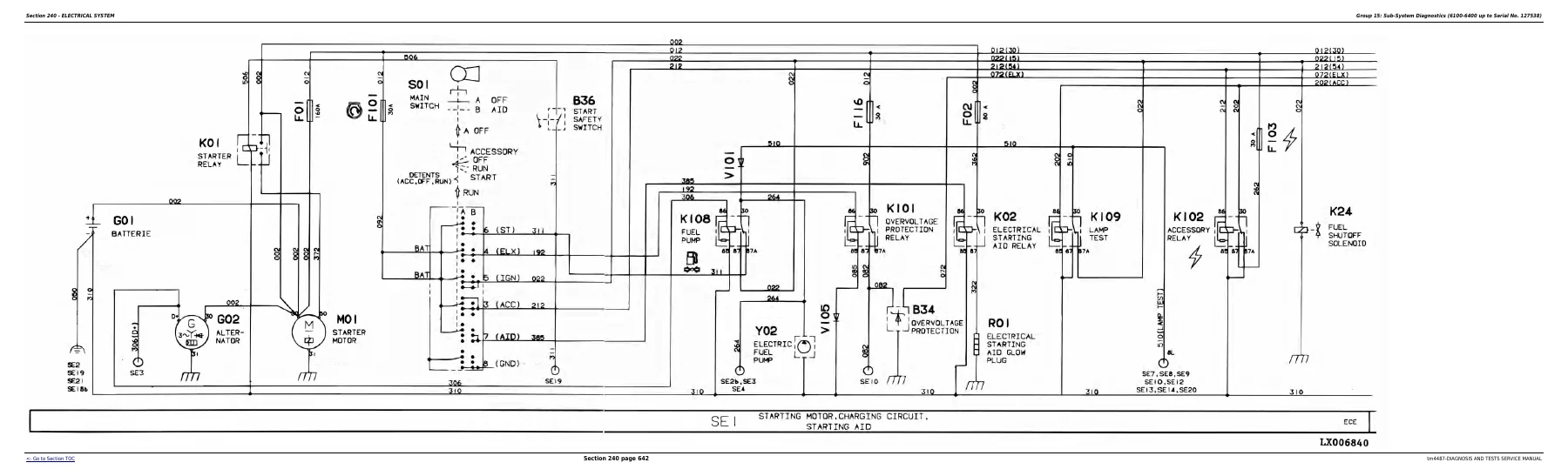
Section 240 is the largest single section and the electrical backbone of the manual. It covers the battery (specifications, operation, testing, electrolyte and terminal checks, booster starting), electrical circuit malfunctions (open, grounded and shorted circuits), and how to read the functional schematics, wiring and harness diagrams. System diagrams are split by serial number break: 6100-6400 up to Serial No. 127538, 6100-6506 from Serial No. 127539, 6600 and 6800 up to Serial No. 139832, 6100 to 6900, and the SE tractors. Sub-system diagnostics run through starting and charging, instrument unit and lighting, display unit, handbrake monitoring, horn, cigarette lighter and operator’s seat, front and rear PTO, front wheel drive, differential lock, brakes, hazard warning and turn signal lights, lights, work lights, power outlet sockets, radio and dome/console lights, blower and air conditioning, wipers and washers, clutch cooling, beacon light and electronic rockshaft control. Component tests include voltage checks, relay and solenoid resistance and current-draw tests, switch continuity charts and the CCD bus test procedures for tractors with HCU only, HCU and RCU, HCU and BCU, and HCU, RCU and BCU (PRF).
Transmissions
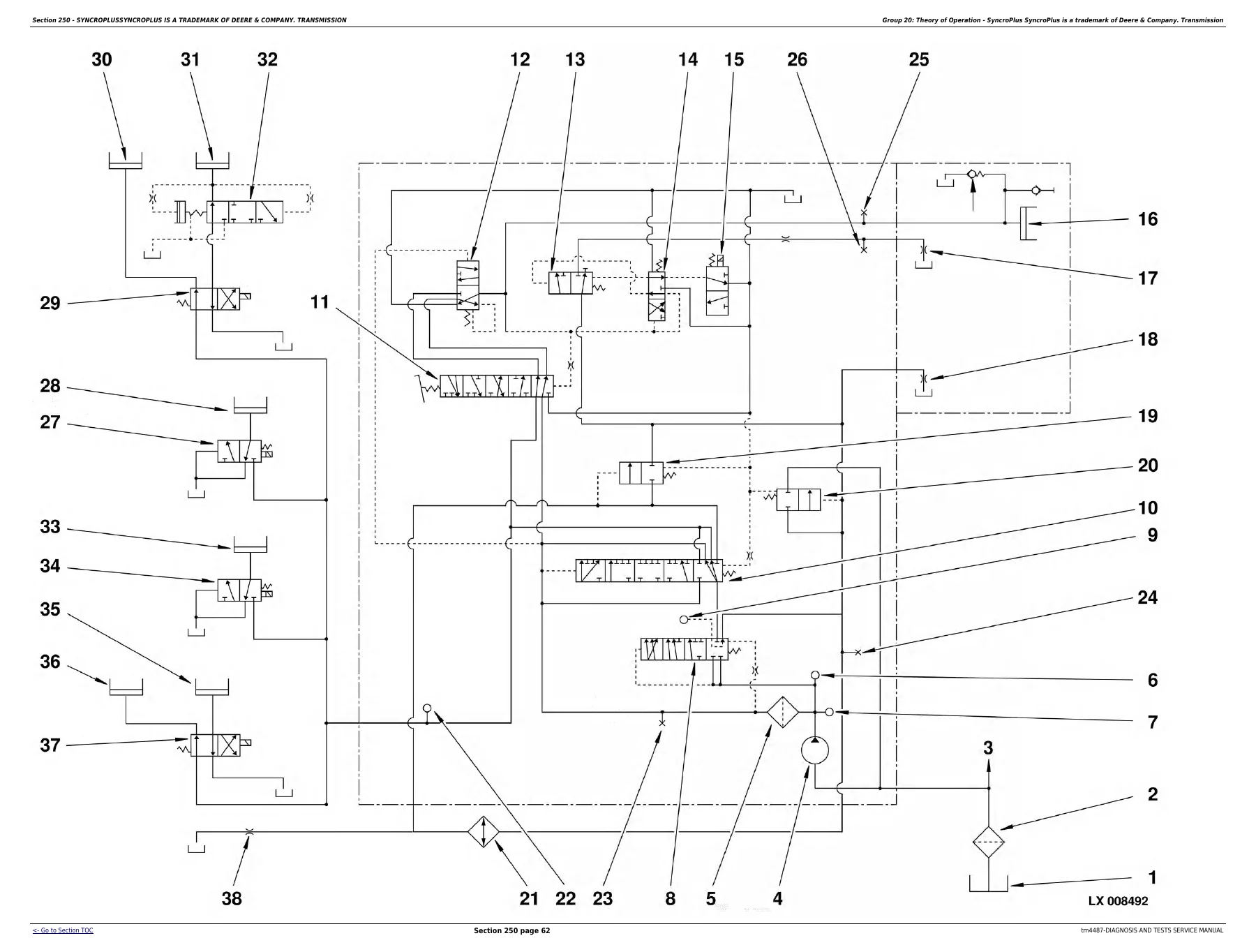
Section 250 covers the SyncroPlus transmission: operational checks, system diagnosis, system tests, and theory of operation including the 12, 15 and 18-speed layouts, creeper transmission, lubrication system, shift operation, synchronisation and the Perma-Clutch 2. Section 251 covers the PowrReverser: operational checks, system diagnosis, system tests and theory of operation with the module design and powerflow, valves and hydraulic circuit. Section 255 covers the PowrQuad transmission: operational checks, system diagnosis using the performance monitor, adjustments, and theory of operation covering housings, planetary operation, air pump, transmission oil pump, clutch oil manifold, reverse brake housing, forward/reverse controls, hydraulic circuit diagrams, filter relief valve, pressure regulating valve, forward-reverse modulation, EOV circuit, electrical reverser control, speed control circuit, speed modulation, clutch cooling and oil cooler system.
Drive Systems
Section 256 covers the front wheel drive clutch (layouts and oil/power flows for 6100-6600 tractors up to and from transmission serial number breaks, plus 6800 and 6900 tractors), the differential (layouts and power flow when moving straight ahead and cornering, plus oil flow with lock engaged and disengaged), final drives, rear PTO options (PTO modulating valve and solenoid valve, clutch and brake theory of operation, lube cut-off valve, power flow for 540 rpm, 540/1000 rpm reversible, and 540/540E/1000 rpm shiftable versions) and the front PTO (sectional view and operation). System tests include FWD clutch system pressure, differential lock system pressure, rear PTO brake and clutch pressure, PTO modulating valve operating check, and front PTO pressure testing.
Steering and Brakes
Section 260 covers steering and brakes in depth. Operational checks, system diagnosis tables for hydrostatic steering, hydraulic brakes (6100-6600), handbrake, hydraulic trailer brake and air brake system. System tests include checking the steering system for external and internal leakage, checking the steering valve for leakage, testing leaf springs, hydraulic connections, shock valve testing and adjustment, brake system checks, bleeding procedures for the brake valve and rear brakes, brake piston travel measurement, stop light switch adjustment, handbrake adjustment, trailer brake valve testing and air brake system checks. Theory of operation covers the complete system, hydrostatic steering (steering valve, metering unit, oil flow in neutral and emergency steering), brake valve layout and operation, handbrake, hydraulic trailer brakes and the air brake system.
Hydraulic System
Section 270 is the hydraulic reference. It includes operational checks, system diagnosis in the standard hydraulic system and in the LSC hydraulic system on SE tractors, and system tests covering charge pump lube oil pressure, hydraulic pump system pressure checking and adjustment, load-sensing valve adjustment, pilot (load sense) pressure, dynamic pressure difference, internal leakage causes, SCV fault diagnosis, independent control valve faults, rockshaft pressure relief valve, Power Beyond application valve adjustment, hydraulic pump and charge pump flow tests, and checking, calibrating and adjusting the rockshaft control. Diagnostic and calibration procedures for the hitch control unit (HCU) run through both the AL78061 and the AL81198, AL110388 and AL112325 units, with full service code lists, diagnostic address lists, calibration procedures, stepper motor and rockshaft valve checks, position sensor and draft sensor adjustment, and the procedure for Service Code 050. Theory of operation covers hydraulic symbols to ISO 1219, the charge pump, hydraulic pumps (operation modes from engine off through cranking, stand-by, extend, stop, stall and retract), hydraulic oil filter, oil cooler, primary filter, shuttle valves, main block with inlet priority valve, Power Beyond valve, rockshaft and lift cylinders, position sensor, draft sensor, operation unit, electronic hitch control unit, selective control valves (100, 200 and 300 series), quick couplers and the independent control valve.
Operator’s Cab
Section 290 covers air conditioning system diagnosis, ventilation and heater diagnosis, and operator’s seat diagnosis, with theory of operation for the air conditioning system (heat exchange principle, R134a refrigerant, refrigerant circuit layout and function, compressor, condenser, receiver-drier, expansion valve, thermostat switch, evaporator, high/low pressure switch) and the ventilation and heater system on both 6100-6900 and SE tractors. Section 299 provides drawings and dimensions for dealer-fabricated special tools.
Why This TM4487 Manual Matters
Diagnosing a modern agricultural tractor without the correct service code tables, pressure specifications and wiring diagrams is guesswork. This John Deere 6100-6900 and SE Tractors diagnosis and tests manual gives you the exact addresses, voltages, pressures, flow rates and resistance values that the tractor’s control units expect, and the step-by-step diagnostic sequences to isolate a fault to a specific circuit or component. Whether you are chasing an intermittent HCU code, setting up a PowrQuad transmission after repair, calibrating the rockshaft after replacing a sensor, or tracing a no-start condition through the starting and charging circuit, the procedure is here. The electrical schematics cover the serial number breaks so you are looking at the diagram that matches the tractor in front of you, and the hydraulic circuit diagrams cover both the mechanical and electrical reverser control variants.
IMAGES PREVIEW
Instant PDF Delivery
This John Deere TM4487 service manual is delivered as an instant PDF download after payment. No shipping, no waiting for a disc or a printed binder. The file opens on any device — desktop, laptop, tablet or smartphone — and individual pages can be printed for use in the workshop. Keep the complete manual on a shop computer, print the sections you need for a specific job, or carry it on a tablet out at the machine. One purchase, permanent access to the full diagnosis and tests reference for the 6100, 6200, 6300, 6400, 6506, 6600, 6800, 6900, SE6100, SE6200, SE6300 and SE6400 tractors.
Reviews
There are no reviews yet.