
Haulotte HS3388RT HS4388RT HS5388RT Repair Manual 242 033 0970 – Full PDF Workshop Manual
Original price was: $55.95.$34.95Current price is: $34.95.
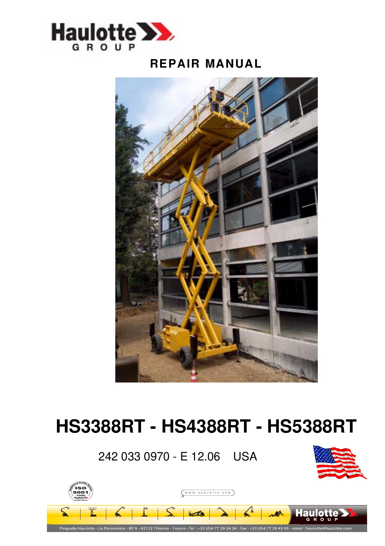
Complete 221-page Haulotte repair manual for the HS3388RT, HS4388RT and HS5388RT scissor platforms – document 242 033 0970 – E 12.06. Includes full specifications, electrical and hydraulic diagrams, preventive maintenance sheets, troubleshooting flow charts and step-by-step corrective repair procedures.
Description
Published by Haulotte under document reference 242 033 0970 – E 12.06 (USA), this repair manual covers the HS3388RT, HS4388RT and HS5388RT self-propelled scissor platforms end to end: machine specifications, electrical and hydraulic schematics, scheduled maintenance, operating-incident tables and fault-finding flow charts, and a full library of corrective maintenance sheets. It is the document a workshop reaches for when a scissor platform comes in with a fault, when a lifting cylinder has to come out, or when a pressure limiter must be set back to its correct value after a repair. All 221 pages of the original file are included.
File Details
- Manual type: Repair manual
- Brand: Haulotte
- Models covered: HS3388RT, HS4388RT, HS5388RT
- Document reference: 242 033 0970 – E 12.06 (USA)
- Language: English
- Page count: 221
- File format: PDF
Chapters Covered
- 1 – Safety Rules
- 2 – Specification
- 3 – Safety System
- 4 – Electrical Diagram
- 5 – Hydraulic Diagrams
- 6 – Maintenance
- 7 – Decals
- 8 – Preventive Maintenance Sheets
- 8 – Operating Incidents
- 9 – Corrective Maintenance Sheets
Safety Rules and the Machine Safety System
Chapter 1 sets out the hazard classes anyone working on the machine operates under – electrocution with a minimum safe approach distance chart by line voltage, tip-over limits including the maximum allowable side force (100 lbs / 445 N ANSI & CSA) and maximum allowable manual force (90 lbs / 400 N CE), fall hazards, collision, component damage, explosion and fire, damaged machine, crushing and bodily injury hazards – plus battery safety rules and the Beaufort wind scale. Chapter 3 documents the hardware behind those rules: the chassis box relay and fuse functions (KA2, KA46, KP1, KT2, KMG, FU1 through FU11), the chassis and platform emergency stop buttons SB1 and SB2, the tilt sensor SQ1, the 12 metre travel cut-off SQ12, the air filter, oil pressure and hydraulic oil temperature contacts B1 to B4, the overload contact B6 and the stabiliser pressure switches and indicator circuits B7 to B14.
Machine Specifications and Tightening Torques
Chapter 2 carries the individual specification tables for each of the three models, so you are reading HS3388RT figures against HS3388RT data and not against a figure borrowed from the larger machine. It lists overall dimensions, platform dimensions, extension length, ground clearance, wheelbase, inside and outside turning radii with and without stabilisers, working height, maximum and minimum floor height, gradeability, travel and lifted speeds, raise and lower times loaded and unloaded, hydraulic tank and fuel tank capacities, tyre size, maximum force on one wheel and maximum ground pressure on hard and loose ground. It also carries the tightening torque tables – large thread and fine thread values for 8.8, 10.9 and 12.9 grades from M6 up to M30 – and the wheel nut tightening torque.
Electrical Diagrams
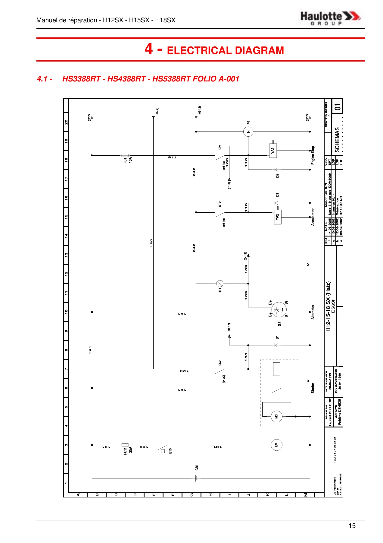
Chapter 4 reproduces the complete electrical schematics across folios A-001 to A-005 for the diesel machines, with a separate folio set for the LP GAS version, all laid out on the original coordinate grid so wire numbers, terminal references and component designations can be traced exactly as drawn. Supporting pages give the positions of the electric components on the mother board, the screw and connector references (battery, starter, accelerator control, main supply after contactor, emergency stop circuit, console connector, horn, gas electrovalve option, proportional valve output, buzzer, PVG connectors), the relay and fuse assignments, and the layout of the diagnosis assistance light indicators for the electrovalves.
Hydraulic Diagrams
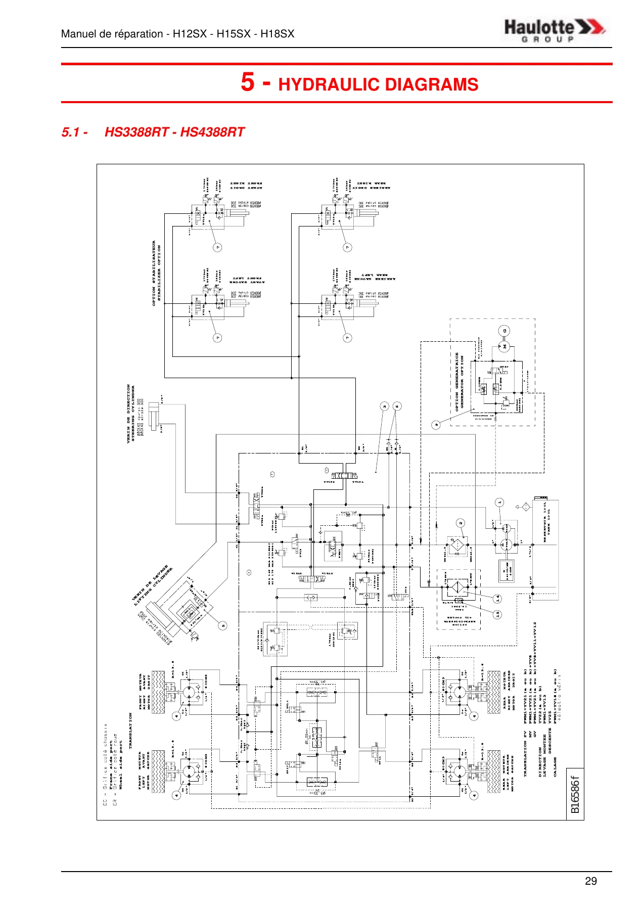
Chapter 5 contains the hydraulic schematics – section 5.1 for the HS3388RT and HS4388RT, section 5.2 for the HS5388RT with its high and low lifting cylinders. Every circuit is annotated with its working pressures (240 bar / 3480 PSI main and travel, lifting pressures, steering, stabiliser, cooler and generator options) and with the electrovalve designations YV8 through YV25 that appear again in the fault-finding charts, so a hydraulic fault can be followed from the diagram straight into the troubleshooting pages.
Maintenance
Chapter 6 is the scheduled-maintenance backbone. It gives general and specific recommendations, the procedure for putting the machine into the maintenance configuration with the maintenance stands, and the procedure for cutting and restoring the electric power supply. The maintenance plan lists the consumables and their specifications – motor oil SAE 15W40, gearbox oil SAE 90, hydraulic oil to AFNOR 48602 ISO VG 46 with a biodegradable option, extreme pressure lithium grease, lead-free grease and lithium grease. The maintenance diagram and summary table then set out what is done daily, for the first 50 hours, and at 50, 250, 500, 1000, 2000 and 3000 hour intervals, including hydraulic filter cartridge changes, wheel reducer draining and refilling, slideway greasing, wheel nut torque checks and hydraulic circuit draining.
Decals and Label Positions
Chapter 7 catalogues the decals fitted to these machines with part numbers, descriptions and quantities, separated into the yellow, orange and red label groups, other labels, model-specific labels for each of the three platforms, and the option-specific labels for cylinder stabilising and biodegradable oil. The label positioning pages show where each decal belongs on the machine, in both the standard and LP GAS versions, so a machine can be brought back to its correct marking after bodywork or a repaint.
Preventive Maintenance Sheets
Chapter 8 opens with five illustrated preventive maintenance sheets: P007 checking and changing the oil of a wheel reducing gear, P015 checking and filling the hydraulic oil tank, P016 replacing the hydraulic filter cartridge, P017 greasing the steering wheel pivots, and P018 greasing the slides. Each sheet lists its preliminary operations, the tools or lubricants required and the steps in sequence.
Operating Incidents and Fault-Finding Flow Charts
The operating incidents chapter is the diagnostic half of the manual. It begins with incident tables covering general operation, the platform lifting system, the travel system and the steering system, each laying out the anomaly, its probable causes and the solution. It then moves into the numbered breakdown detection flow charts DP100 to DP127 – no up or down movement from the platform or chassis control panel, no travel in either direction, no steering, noisy hydraulic pump, no centralised stabilising, motor will not start with or without starter activation, motor starts then stops after 5 seconds, no motor acceleration, high travel speed unavailable, only micro speed available, and the gas-to-petrol changeover fault. Each chart is a logical decision path with voltage readings, terminal numbers, wire numbers and the sheet to go to next.
Corrective Maintenance Sheets
Chapter 9 is the repair library: forty illustrated corrective maintenance sheets covering hoses, tilt detector, hydraulic filter, horn, tilt buzzer, wheels, relays, printed circuit, electronic module U1, platform box cards, emergency stops, chassis control panel components, manipulators, balancing valves, pressure switches, non-return valves, circuit selectors, pressure limiters and their adjustment, level detector, gas safety valve, lifting cylinder, wheel reducer and hydraulic travel motor, steering cylinder, steering pivot, platform extension, platform, scissors, scissor axles and rings, chassis covers, starter battery, end of travel contacts, coils, electrovalves, distribution unit, stabiliser cylinder, hydraulic pump, diesel motor, LP GAS motor and gas hoses. Where a procedure has a pressure or load setting, the sheet gives the table – for example the lifting pressure limiter adjustment with nominal load and nominal load +10% figures for each model, and the pressure switch adjustment loads.
Torque, Pressure and Adjustment Values You Can Work From
This Haulotte repair manual is not a general guide with the numbers left out. It carries the tightening torque tables by thread and grade, wheel nut torque, the general hydraulic pressure of 240 bar / 3480 PSI, travel hydraulic pressure of 240 bar / 3480 PSI, and the model-specific lifting pressures – 143 bar for the HS3388RT, 174 bar for the HS4388RT and 160 bar for the HS5388RT in the specification tables, with the pressure limiter adjustment table giving the working figures to set against. Working heights run from 11.80 m on the HS3388RT through 14.80 m on the HS4388RT to 17.80 m on the HS5388RT, and the maximum platform capacities differ between models, so the manual always tells you which machine the figure belongs to.
Put the Correct Information in Front of the Job
Scissor platform work is unforgiving of guesswork. Lifting pressures, stabiliser logic, tilt detection, overload contacts and end-of-travel switches are all interlocked, and a machine reassembled against the wrong value will either refuse to work or work in a way that is not safe. The flow charts in this manual walk you through the interlocks in the order the control system checks them, so a no-lift fault is traced to the fuse, the contact, the coil or the module rather than being guessed at with a spanner in hand.
For a workshop running HS3388RT, HS4388RT or HS5388RT machines, that means planned maintenance, fault diagnosis, hydraulic and electrical repair, cylinder and pump replacement, pressure limiter setting and decal restoration are all supported by one document. The illustrated corrective sheets cover the removal and refitting sequence, the cautions about hot oil and slinging components, the torque to tighten to, and the purge and level check to finish with – the same structure a technician would work to on the shop floor.
Delivery is immediate. The manual is supplied as a PDF that opens on a laptop, tablet or phone in the workshop, and any page can be printed for the machine or the bench so the sheet you are working from does not have to live on a screen. No shipping, no waiting for a courier – the file is yours to download as soon as your order is complete.
IMAGES PREVIEW


Reviews
There are no reviews yet.