★ TRUSTED BY 321,897+ PROFESSIONALS WORLDWIDE
🏒
Trusted Business
Verified & Licensed
πŸ›‘οΈ
Virus Free Files
100% Safe Downloads
πŸ”’
Secure Payment
SSL Protected
⚑
Instant Delivery
Available Immediately
Sale!

John Deere 410D 510D Backhoe Loaders Repair Technical Manual TM1513 (2005)

Original price was: $39.95.Current price is: $23.95.

Complete John Deere factory repair technical manual TM1513 for the 410D and 510D backhoe loaders. Full teardown, overhaul and reassembly procedures for engine, transaxle, MFWD axles, loader, backhoe, hydraulics, electrical, brakes and cab. Instant PDF download.

⚑
Instant PDF Download
Available immediately
πŸ’Ύ
Save to Your Device
Download & keep forever
πŸ›‘οΈ
Antivirus Scanned
100% virus-free
🌍
Trusted Worldwide
175,000+ customers

Description

John Deere 410D 510D Backhoe Loaders Repair Technical Manual TM1513

The John Deere 410D 510D Backhoe Loaders Repair Technical Manual TM1513 (2005) is the factory repair guide covering the complete 410D and 510D backhoe loader line. Published 08 JUN 05 in English, this repair technical manual walks a technician through teardown, inspection, overhaul, reassembly, adjustment and torque procedures for every major system on the machine. The 410D and 510D share the John Deere 4045 diesel engine family β€” naturally aspirated 4045D and turbocharged 4045T β€” and this TM1513 manual covers both configurations, along with the multiple serial number breaks that separate early, intermediate and later production machines. Whether you are diagnosing a hydraulic fault, resealing a cylinder, rebuilding the transaxle, or re-torquing the ROPS mounting bolts, this repair technical manual gives you John Deere’s own procedures, specifications and tolerances.

File Details

  • Manual Type: Repair Technical Manual
  • Brand: John Deere
  • Models: 410D, 510D Backhoe Loaders
  • Document Number: TM1513
  • Publication Date: 08 JUN 05
  • Language: English
  • Format: PDF (instant digital download)
  • Page Count: 976 pages

Chapters Covered

The TM1513 repair manual is organized by John Deere’s standard section and group numbering, making it easy to jump straight to the system you need.

  • Section 00 – General Information: Safety Information; General Specifications; Torque Values (Unified Inch and Metric Cap Screw Torque Values, Additional Metric Cap Screw Torque Values, ROPS Torque Specifications, Service Recommendations for Flare, O-Ring Boss, Flat Face O-Ring Seal and Four Bolt Flange Fittings); Fuels and Lubricants (Fuel Specifications, Engine Oil, Transaxle Oil, Hydraulic and Reverser Oil, Mechanical Front Wheel Drive Oil, Grease, Engine Coolant)
  • Section 01 – Wheels: Powered Wheels and Fastenings; Non-Powered Wheels and Fastenings; Tire Removal and Installation
  • Section 02 – Axles and Suspension Systems: Removal and Installation; Input Drive Shafts and U-Joints; Non-Powered Wheel Axles (hub, spindle, knuckle, tie rod, toe-in adjustment); Powered Wheel Axle (MFWD) β€” APL-745 and APL-2035 planetary drives, constant velocity joints, differentials; Axles, Bearings and Reduction Gears (rear axle disassembly, planetary pinion carrier, axle housing, axle shaft); Hydraulic System (MFWD control valve)
  • Section 03 – Transmission: Removal and Installation (transaxle, reverser with torque converter); Controls Linkage; Input Drive Shafts and U-Joints; Gears, Shafts, Bearings and Power Shift Clutch (reverser oil filter, directional control valve, pressure regulating valve, torque converter, oil pump, planetary assembly, forward clutch, reverse brake, output shaft, transaxle case, differential, shifter shafts, transmission drive shaft, differential drive shaft, transfer case); Hydraulic System
  • Section 04 – Engine: Removal and Installation (4045 John Deere Engine β€” see CTM8 for complete component-level engine information); fuel system bleeding
  • Section 05 – Engine Auxiliary Systems: Cold Weather Starting Aids (coolant heater, starting aid nozzle, starting aid solenoid); Engine Cooling System (fan, fan belts, radiator, oil cooler, coolant recovery bottle); Speed Controls; Intake System (air cleaner, air intake leak testing); External Fuel Supply Systems (fuel tank)
  • Section 06 – Torque Converter: Turbine, Gears and Shafts β€” removal, installation, air testing
  • Section 09 – Steering System: Hydraulic System (steering column, tilt steering column, steering valve, non-powered axle steering cylinder, MFWD axle steering cylinder for both APL-745 and APL-2035, tracking angle adjustment)
  • Section 10 – Service Brakes: Active Elements (brake piston housing, brake disk, pressure plate, transaxle case braking surface reclamation and polishing); Hydraulic System (brake valve, pedal adjustment, brake bleeding)
  • Section 11 – Park Brake: Active Elements (brake band, brake drum); Hydraulic System (park brake actuator, park brake controls)
  • Section 16 – Electrical Systems: Batteries, Support and Cables; Alternator, Regulator and Charging System Wiring; Lighting System; Wiring Harness and Switches (Deutsch and Weather Pack connectors, fuses, loader lever switch, gear shift lever switch, FNR switch, brake light switch, forward and reverse solenoids, clutch disconnect solenoid, reverse alarm, MFWD solenoid and indicator, reverser pressure switch, park brake solenoid and sensing switch); System Controls (logic module, return-to-dig switch); Instruments and Indicators; Motors and Actuators (starting motor, starter relay)
  • Section 17 – Frames: Frame Installation (welding repair of major structures, RIVNUT fasteners); Chassis Weights (frame bumper, counterweights)
  • Section 18 – Operator’s Station: Removal and Installation (cab or ROPS); Operator Enclosure (right and left cab doors, wiper motors, windows, headliner); Seat and Seat Belt; Heating and Air Conditioning (heater core, heater control valve, blower motor, air ducts, condenser, receiver/dryer, evaporator, expansion valve, compressor R12 and R134a service)
  • Section 19 – Sheet Metal and Styling: Hood and Engine Enclosure; Miscellaneous Shields (steps, battery box, MFWD shaft guard); Grille and Grille Housing; Fenders
  • Section 20 – Safety, Convenience and Miscellaneous: Radio; Horn and Warning Devices (horn, reverse alarm)
  • Section 21 – Main Hydraulic System: Hydraulic System (charge pump, hydraulic pump, pump drive shaft, stroke control valve housing, destroke solenoid, crankcase relief valve, pressure compensator valve, priority valve, hydraulic oil filter, hydraulic oil cooler, oil cooler bypass valve, surge relief valve, hydraulic reservoir)
  • Section 31 – Loader: Removal and Installation; Bucket (bucket, cutting edge); Controls Linkage (bucket level indicator, return-to-dig switch, loader control valve linkage); Frames (bucket cylinder linkage); Hydraulic System (loader control valve for both early and later serial ranges, circuit relief valves, anti-cavitation, priority section, bucket/boom/auxiliary sections, wiper ring and seal replacement, boom cylinder, bucket cylinder, cylinder disassembly and assembly)
  • Section 33 – Backhoe: Bucket (bucket and bucket links, bushings, tooth shanks, cutting edge); Control Linkage (backhoe valve linkage, stabilizer valve linkage, standard and heavy lift boom lock linkage); Frames (dipperstick, boom, swing frame, extendible dipperstick for early and later serial ranges, collar, extension, bearing strips, support pads); Hydraulic System (Gresen and Husco backhoe control valves, relief valves, selective flow solenoid valve, stabilizer valve, bucket cylinder, crowd cylinder, boom cylinder, swing cylinder, stabilizer cylinder, extendible dipperstick extension cylinder)

IMAGES PREVIEW

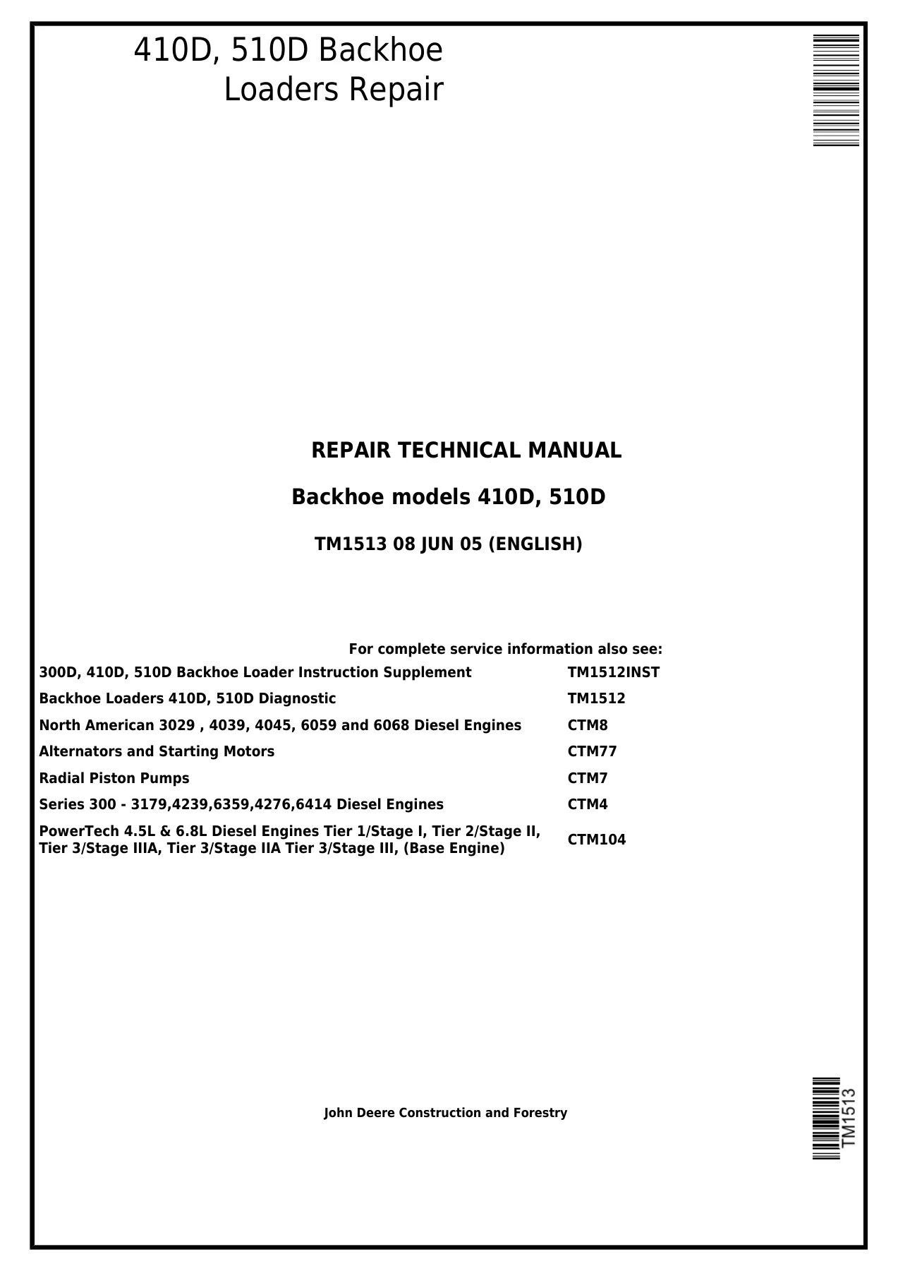
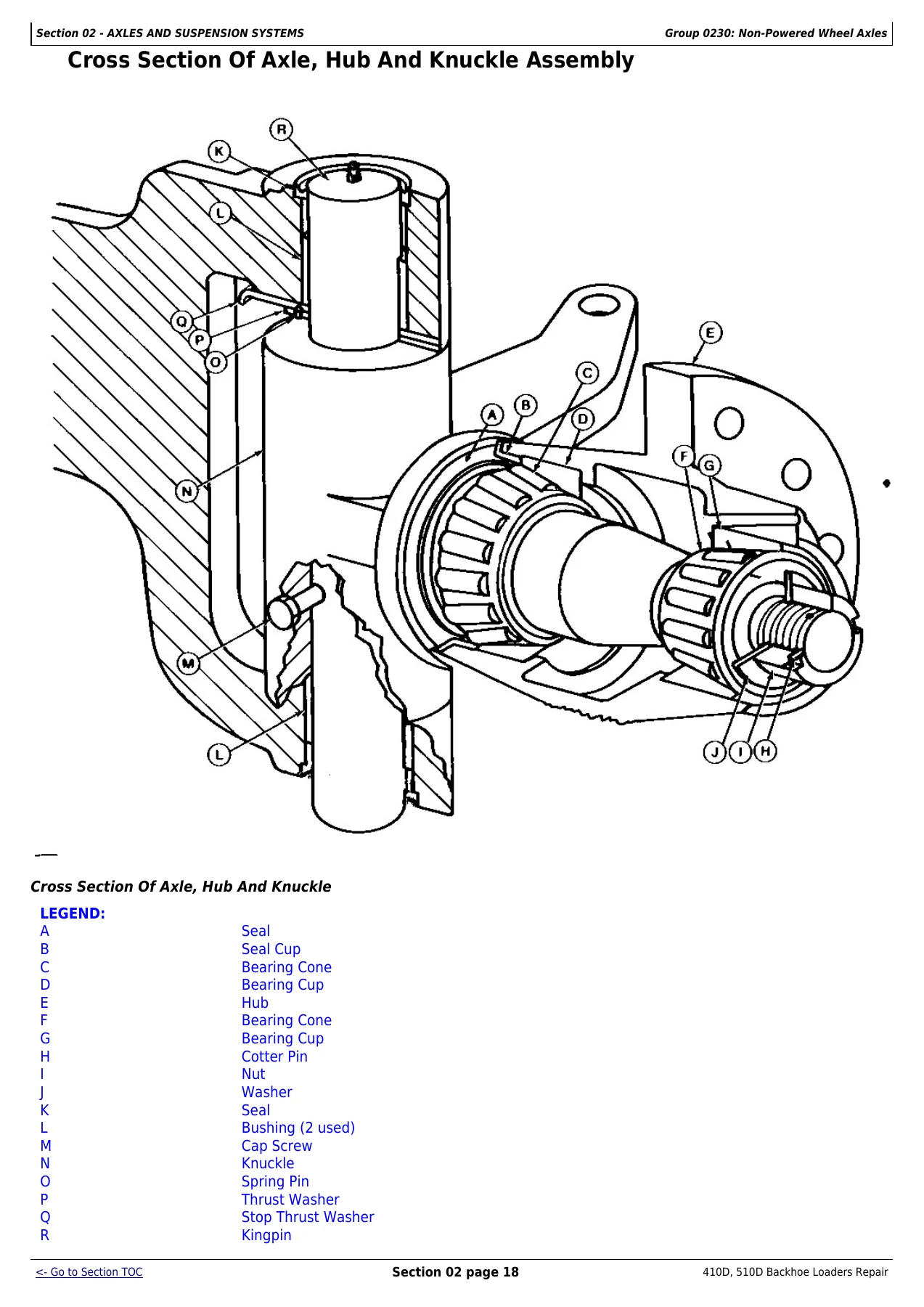
John Deere 410D 510D Backhoe Loaders Repair Technical Manual TM1513 (2005) β€” PDF page 1 preview
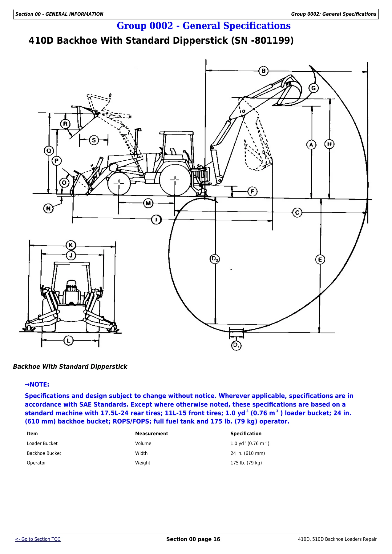
John Deere 410D 510D Backhoe Loaders Repair Technical Manual TM1513 (2005) β€” PDF page 23 preview
John Deere 410D 510D Backhoe Loaders Repair Technical Manual TM1513 (2005) β€” PDF page 103 preview

Across all of these sections, the TM1513 manual follows John Deere’s standard service format: an exploded view or cross-section drawing for each assembly, a summary of essential tools and service parts, step-by-step removal and installation procedures, wear tolerances and clearances, and the specific torque values needed at each stage of reassembly. Sub-assemblies such as the APL-745 and APL-2035 MFWD axle differentials, the forward clutch, reverse brake, and the entire backhoe hydraulic valve stack are broken down to the individual component level, so even a full rebuild is supported. The electrical section covers both Deutsch and Weather Pack connector systems, and the hydraulic sections cover the Gresen and Husco backhoe valves as well as the John Deere radial piston main pump, priority valve, and the various relief, bypass and surge protection valves in the system.

Serial Number Coverage

John Deere split 410D and 510D production across multiple serial number breaks, and TM1513 recognizes them throughout. Where procedures, torque values, part numbers or specifications change between serial ranges, the manual calls that out at the point of use. The main serial divisions addressed are:

  • 410D, 510D (SN -801199) β€” early production
  • 410D, 510D (SN 801200-) β€” later production
  • 410D (SN -796854), 510D (SN -796890) β€” early transaxle and MFWD configurations
  • 410D (SN 796855-), 510D (SN 796891-) β€” later transaxle and MFWD configurations
  • 410D (SN 796855-801199), 510D (SN 796891-801199) β€” intermediate production
  • Additional serial breaks within individual sections (for example, 410D SN -787384 vs SN 787385- for the extendible dipperstick)

Always confirm your machine’s serial number against the applicable range before following a procedure, particularly for torque values, brake shimming, hydraulic valve identification and MFWD axle variants.

Engine Coverage

The 410D and 510D use the John Deere 4045 diesel engine in naturally aspirated (4045D) and turbocharged (4045T) form. Engine removal and installation for the machine is covered in Section 04 of TM1513. For complete component-level engine overhaul information β€” cylinder head, valve train, pistons, bearings, injection pump, turbocharger and so on β€” John Deere’s separate component technical manual CTM8 is referenced for the 4045 engine family. The TM1513 manual provides the machine-level removal, installation, fuel system bleeding and integration procedures needed to get the engine in and out of the 410D and 510D and back into service.

Complete PDF Bookmark Tree

Complete Bookmarks

The complete bookmarks in the β€œJohn Deere 410D 510D Backhoe Loaders Repair Technical Manual TM1513 (2005)” are as follows:

Table of contentsp. 2
FOREWORDp. 5
Section 00 – GENERAL INFORMATIONp. 8
Group 0001 – Safety Informationp. 8
Handle Fluids Safely-Avoid Firesp. 8
Prevent Battery Explosionsp. 8
Prepare for Emergenciesp. 8
Prevent Acid Burnsp. 10
Handle Chemical Products Safelyp. 10
Avoid High-Pressure Fluidsp. 11
Park Machine Safelyp. 11
Support Machine Properlyp. 12
Wear Protective Clothingp. 13
Work in Clean Areap. 13
Service Machines Safelyp. 13
Work In Ventilated Areap. 14
Illuminate Work Area Safelyp. 14
Replace Safety Signsp. 15
Use Proper Lifting Equipmentp. 15
Remove Paint Before Welding or Heatingp. 15
Avoid Heating Near Pressurized Fluid Linesp. 17
Keep ROPS Installed Properlyp. 17
Service Tires Safelyp. 18
Avoid Harmful Asbestos Dustp. 18
Practice Safe Maintenancep. 20
Use Proper Toolsp. 20
Dispose of Waste Properlyp. 21
Live With Safetyp. 21
Group 0002 – General Specificationsp. 23
410D Backhoe With Standard Dipperstick (SN -801199)p. 23
410D Backhoe Loader With Standard Dipperstick (SN-801199)p. 24
410D Backhoe With Standard Dipperstick (SN 801200- )p. 25
410D Backhoe Loader With Standard Dipperstick (SN 801200- )p. 26
410D Heavy Lift Backhoe Loader (SN -801199)p. 27
410D Heavy Lift Backhoe Loader (SN 801200- )p. 29
410D Backhoe Loader Specifications (SN -801199)p. 31
410D Backhoe Loader Specifications (SN 801200-)p. 34
410D Backhoe Loader And Backhoe Bucketsp. 37
410D Backhoe Loader Lifting Capacitiesp. 38
510D Backhoe Loader With Standard 2.1 M (6 Ft 11.7 In.) Dipperstick (SN -801199)p. 44
510D Backhoe Loader With Standard 2.1 M (6 Ft 11.7 In.) Dipperstick (SN 801200- )p. 46
510D Backhoe Loader Specifications (SN -801199)p. 48
510D Backhoe Loader Specifications (SN 801200- )p. 51
510D Backhoe And Loader Bucketsp. 53
510D Backhoe Loader Lifting Capacitiesp. 54
410D And 510D Backhoe Loader Drain And Refill Capacitiesp. 57
Group 0003 – Torque Valuesp. 58
Hardware Torque Specificationsp. 58
Checking Wheel Fastener Torquep. 58
ROPS Torque Specificationsp. 58
Unified Inch Bolt and Cap Screw Torque Valuesp. 59
Metric Bolt and Cap Screw Torque Valuesp. 60
Additional Metric Cap Screw Torque Valuesp. 61
Check Oil Lines And Fittingsp. 62
Service Recommendations for 37Β° Flare and 30Β° Cone Seat Connectorsp. 63
Service Recommendations for O-Ring Boss Fittingsp. 64
Service Recommendations for Flat Face O-Ring Seal Fittingsp. 66
Service Recommendations For Inch Series Four Bolt Flange Fittingsp. 67
Service Recommendations for Metric Series Four Bolt Flange Fittingp. 68
Group 0004 – Fuels And Lubricantsp. 69
Fuel Specificationsp. 69
Low Sulfur Diesel Fuel Conditionerp. 69
Storing Fuelp. 69
Do Not Use Galvanized Containersp. 69
Fuel Tankp. 69
Engine Oilp. 70
Transaxle Oilp. 70
Hydraulic And Reverser Oilp. 71
Mechanical Front Wheel Drive Oilp. 71
Greasep. 72
Grease For Extendible Dipperstickp. 73
Alternative and Synthetic Lubricantsp. 73
Lubricant Storagep. 73
Mixing of Lubricantsp. 73
Engine Coolantp. 73
Section 01 – WHEELSp. 75
Group 0110 – Powered Wheels And Fasteningsp. 75
Service Equipment And Toolsp. 75
Specificationsp. 76
Remove And Install Rear Wheel Assemblyp. 76
Remove And Install Front Wheel Assemblyp. 77
Remove And Install Tirep. 78
Group 0120 – Non-Powered Wheels And Fasteningsp. 81
Service Equipment And Toolsp. 81
Specificationsp. 81
Remove And Install Front Wheel Assemblyp. 81
Remove And Install Tirep. 82
Section 02 – AXLES AND SUSPENSION SYSTEMSp. 86
Group 0200 – Removal And Installationp. 86
Service Equipment And Toolsp. 86
Other Materialp. 86
Specificationsp. 86
Remove Non-Powered Front Axlep. 86
Remove And Install Axle Bushingsp. 88
Install Non-Powered Front Axlep. 88
Remove Powered Front Axlep. 91
Install Powered Wheel Axlep. 93
Remove And Install Rear Axlep. 95
Group 0225 – Input Drive Shafts And U-Jointsp. 99
Specificationsp. 99
Remove And Disassemble Drive Shaftp. 99
Assemble And Install Drive Shaftp. 100
Group 0230 – Non-Powered Wheel Axlesp. 102
Service Equipment And Toolsp. 102
Other Materialp. 102
Specificationsp. 102
Cross Section Of Axle, Hub And Knuckle Assemblyp. 103
Remove Hub Assemblyp. 104
Remove Spindle And Knuckle Assemblyp. 105
Install Spindle And Knuckle Assemblyp. 107
Install Hub Assemblyp. 110
Remove Tie Rodp. 112
Install Tie Rodp. 112
Adjust Non-Powered Front Axle Toe-Inp. 113
Group 0240 – Powered Wheel Axle (MFWD)p. 115
Special Or Essential Toolsp. 115
Service Equipment And Toolsp. 117
Other Materialp. 117
Specificationsp. 118
Disassemble Knuckle Housing And Wheel Hub With Planetary Drive-APL-745p. 119
Disassemble Axle Shaft And Constant Velocity Joint-APL-745p. 123
Knuckle Housing And Wheel Hub With Planetary Drive Exploded Viewp. 125
Assemble Axle Shaft And Constant Velocity Joint-APL-745p. 126
Assemble And Adjust Knuckle Housing And Wheel Hub With Planetary-APL-745p. 128
Remove Differential-APL-745 Axlep. 135
Disassemble Differential-APL-745 Axlep. 137
Exploded View Of Pinion Shaft And Carrier Housing-APL-745 Axlep. 142
Exploded View Of Pinion Housing-APL-745 Axlep. 144
Assemble Differential-APL-745 Axlep. 146
Install Differential-APL-745 Axlep. 156
Disassemble Knuckle Housing And Wheel Hub With Planetary Drive-APL-2035p. 158
Disassemble Axle Shaft And Constant Velocity Joint-APL-2035 Axlep. 161
Knuckle Housing And Planetary Hub Exploded View-APL-2035p. 163
Assemble Axle Shaft And Constant Velocity Joint-APL-2035p. 164
Assemble And Adjust Knuckle Housing And Wheel Hub With Planetary-APL-2035p. 166
Remove Differential-APL-2035 Axlep. 174
Disassemble Differential-APL-2035 Axlep. 176
Exploded View Of Differential Housing-APL-2035 Axlep. 178
Exploded View Of Pinion Shaft-APL-2035 Axlep. 179
Adjust Cone Point-APL-2035 Axlep. 180
Assemble Bevel Pinion Shaft-APL-2035 Axlep. 182
Assemble Differential Housing-APL-2035 Axlep. 185
Adjust MFWD Axle Toe-Inp. 191
Group 0250 – Axles, Bearings And Reduction Gearsp. 193
Service Equipment And Toolsp. 193
Other Materialp. 193
Specificationsp. 193
Disassemble Rear Axlep. 193
Disassemble And Assemble Planetary Pinion Carrierp. 195
Disassemble Rear Axle Housingp. 199
Disassemble And Inspect Rear Axle Shaftp. 201
Assemble Rear Axle Shaftp. 203
Assemble Axle Housingp. 205
Grease Rear Axle Shaftp. 210
Group 0260 – Hydraulic Systemp. 212
Remove And Install MFWD Control Valve-(410D-SN -796854)(510D-SN -796890)p. 212
Group 0299 – Dealer Fabricated Toolsp. 214
DF1002 Rolling Drag Torque Barp. 214
Section 03 – TRANSMISSIONp. 219
Group 0300 – Removal And Installationp. 219
Special Or Essential Toolsp. 219
Service Equipment And Toolsp. 219
Other Materialp. 219
Specificationsp. 219
Remove Transaxlep. 220
Install Transaxlep. 224
Remove Reverser With Torque Converterp. 227
Install Reverser With Torque Converterp. 232
Group 0315 – Controls Linkagep. 236
Other Materialp. 236
Specificationsp. 236
Remove And Install Shifter Linkage-(410D-SN -796854)(510D-SN -796890)p. 237
Remove And Install Shifter Linkage 410D-(SN 796855-801199) 510D-(SN 796891-801199)p. 239
Remove And Install Shifter Linkage 410D, 510D (SN 801200- )p. 241
Group 0325 – Input Drive Shafts And U-Jointsp. 243
Specificationsp. 243
Remove And Install Drive Shaftp. 243
Group 0350 – Gears, Shafts, Bearings And Power Shift Clutchp. 244
Special Or Essential Toolsp. 244
Service Equipment And Toolsp. 244
Other Materialp. 245
Specificationsp. 246
Remove And Install Reverser Oil Filter 410D-(SN 796855- ) 510D-(SN 796891- )p. 247
Remove Directional Control Valve And Oil Filterp. 247
Install Directional Control Valve And Oil Filterp. 248
Remove And Install Pressure Regulating Valvep. 249
Remove Torque Converterp. 250
Remove And Disassemble Oil Pump And Manifoldp. 251
Remove And Disassemble Planetary Assemblyp. 253
Remove Rear Coverp. 254
Remove Reverse Brake And Forward Clutchp. 255
Remove Output Shaftp. 256
Disassemble Forward Clutchp. 259
Disassemble And Assemble Reverser Housingp. 261
Assemble Forward Clutchp. 263
Install Output Shaftp. 265
Install Reverse Brake And Forward Clutchp. 267
Install Rear Coverp. 268
Assemble Planetary Assemblyp. 269
Install Planetary Assemblyp. 270
Assemble Oil Pump And Manifoldp. 271
Install Torque Converterp. 274
Transaxle Cross Section 410D-(SN -796854) 510D-(SN -796890)p. 276
Remove Axle 410D-(SN -796854) 510D-(SN -796890)p. 278
Remove Top And Front Transaxle Covers 410D-(SN -796854) 510D-(SN -796890)p. 280
Disassemble Front Cover 410D-(SN -796854) 510D-(SN -796890)p. 281
Remove Differential Assembly 410D-(SN -796854) 510D-(SN -796890)p. 282
Disassemble Differential Assembly 410D-(SN -796854) 510D-(SN -796890)p. 284
Remove Lubrication Lines 410D-(SN -796854) 510D-(SN -796890)p. 286
Remove Shifter Shafts 410D-(SN -796854) 510D-(SN -796890)p. 287
Remove And Disassemble Transmission Drive Shaft 410D-(SN -796854) 510D-(SN -796890)p. 289
Remove Differential Drive Shaft 410D-(SN -796854) 510D-(SN -796890)p. 291
Remove Lubrication Line And Suction Screen 410D-(SN -796854) 510D-(SN -796890)p. 292
Differential Drive Shaft Cone Point Adjustment 410D-(SN -796854) 510D-(SN -796890)p. 294
Assemble Differential 410D-(SN -796854) 510D-(SN -796890)p. 296
Install Park Brake Band 410D-(SN -796854) 510D-(SN -796890)p. 298
Adjust Differential Housing Preload 410D-(SN -796854) 510D-(SN -796890)p. 298
Install Suction Screen And Lubrication Lines 410D-(SN -796854) 510D-(SN -796890)p. 299
Install Differential Drive Shaft 410D-(SN -796854) 510D-(SN -796890)p. 301
Adjust Differential Drive Shaft Rolling Drag Torque 410D-(SN -796854) 510D-(SN -796890)p. 302
Assemble And Install Transmission Drive Shaft 410D-(SN -796854) 510D-(SN -796890)p. 304
Install Shifter Shafts 410D-(SN -796854) 510D-(SN -796890)p. 308
Adjust Transmission Drive Shaft End Play 410D-(SN -796854) 510D-(SN -796890)p. 311
Install Lubrication Lines 410D-(SN -796854) 510D-(SN -796890)p. 311
Install Differential Assembly 410D-(SN -796854) 510D-(SN -796890)p. 312
Adjust Differential Housing Backlash 410D-(SN -796854) 510D-(SN -796890)p. 312
Install Differential Lock Assembly 410D-(SN -796854) 510D-(SN -796890)p. 313
Tighten Brake Band 410D-(SN -796854) 510D-(SN -796890)p. 314
Assemble Front Cover 410D-(SN -796854) 510D-(SN -796890)p. 315
Install Front And Top Covers 410D-(SN -796854) 510D-(SN -796890)p. 316
Install Axles 410D-(SN -796854) 510D-(SN -796890)p. 318
Disassemble Transfer Case (MFWD) 410D-(SN -796854) 510D-(SN -796890)p. 321
Disassemble Output Quill And Shaft 410D-(SN -796854) 510D-(SN -796890)p. 324
Disassemble Idler Shaft 410D-(SN -796854) 510D-(SN -796890)p. 324
Disassemble Clutch Quill 410D-(SN -796854) 510D-(SN -796890)p. 325
Disassemble Clutch Pack 410D-(SN -796854) 510D-(SN -796890)p. 326
Disassemble Idler Gear 410D-(SN -796854) 510D-(SN -796890)p. 328
Disassemble Input Quill And Drive Gear 410D-(SN -796854) 510D-(SN -796890)p. 329
Disassemble Transmission Input Shaft 410D-(SN -796854) 510D-(SN -796890)p. 330
Assemble Transmission Input Shaft 410D-(SN -796854) 510D-(SN -796890)p. 330
Assemble Input Quill And Drive Gear 410D-(SN -796854) 510D-(SN -796890)p. 331
Assemble Idler Gear 410D-(SN -796854) 510D-(SN -796890)p. 331
Assemble Clutch Pack 410D-(SN -796854) 510D-(SN -796890)p. 333
Assemble Clutch Quill 410D-(SN -796854) 510D-(SN -796890)p. 336
Assemble Idler Shaft 410D-(SN -796854) 510D-(SN -796890)p. 336
Assemble Output Quill And Shaft 410D-(SN -796854) 510D-(SN -796890)p. 336
Install Shafts And Quills 410D-(SN -796854) 510D-(SN -796890)p. 338
Transaxle Cross Section 410D-(SN 796855- ) 510D-(SN 796891- )p. 343
Remove And Install Transaxle Oil Filterp. 343
Remove Brake Lines, Shift Bracket And Link 410D-(SN 796855- ) 510D-(SN 796891- )p. 344
Remove Park Brake Actuator 410D-(SN 796855- ) 510D-(SN 796891- )p. 344
Remove Axles And Brakes 410D-(SN 796855- ) 510D-(SN 796891- )p. 345
Remove Transaxle Cover 410D-(SN 796855- ) 510D-(SN 796891- )p. 346
Remove Park Brake Shaft 410D-(SN 796855- ) 510D-(SN 796891- )p. 347
Remove Transmission Lube Pump 410D-(SN 796855- ) 510D-(SN 796891- )p. 347
Remove Differential Lock 410D-(SN 796855- ) 510D-(SN 796891- )p. 348
Remove Differential 410D-(SN 796855- ) 510D-(SN 796891- )p. 349
Disassemble Differential 410D-(SN 796855- ) 510D-(SN 796891- )p. 350
Remove Third And Fourth Speed Shifter Shaft And Fork 410D-(SN 796855- ) 510D-(SN 796891- )p. 351
Remove Transmission Drive Shaft 410D-(SN 796855- ) 510D-(SN 796891- )p. 352
Remove First And Second Speed Shifter Shaft And Fork 410D-(SN 796855- ) 510D-SN 796891- )p. 353
Remove Differential Drive Shaft 410D-(SN 796855- ) 510D-(SN 796891- )p. 355
Remove And Install Oil Lines 410D-(SN 796855- ) 510D-(SN 796891- )p. 357
Disassemble Lube Pump 410D-(SN 796855- ) 510D-(SN 796891- )p. 358
Assemble Lube Pump 410D-(SN 796855- ) 510D-(SN 796891- )p. 359
Disassemble Transmission Drive Shaft 410D-(SN 796855- ) 510D-(SN 796891- )p. 360
Assemble Transmission Drive Shaft 410D-(SN 796855- ) 510D-(SN 796891- )p. 363
Assemble Differential 410D-(SN 796855- ) 510D-(SN 796891- )p. 367
Adjust Differential Drive Shaft Cone Point 410D-(SN 796855- ) 510D-(SN 796891- )p. 370
Adjust Differential Housing Preload 410D-(SN 796855- ) 510D-(SN 796891- )p. 371
Install Differential Drive Shaft 410D-(SN 796855- ) 510D-(SN 796891- )p. 373
Adjust Differential Drive Shaft Rolling Drag Torque 410D-(SN 796855- ) 510D-(SN 796891- )p. 380
Check Second Speed Gear End Play-(410D-SN 796855- )(510D-SN 796891- )p. 382
Install First And Second Speed Shifter Shaft And Fork 410D-(SN 796855- ) 510D-(SN 796891- )p. 383
Install Differential 410D-(SN 796855- ) 510D-(SN 796891- )p. 384
Adjust Differential Housing Backlash 410D-(SN 796855- ) 510D-(SN 796891- )p. 384
Install Differential Lock Assembly 410D-(SN 796855- ) 510D-(SN 796891- )p. 385
Install Transmission Drive Shaft 410D-(SN 796855- ) 510D-(SN 796891- )p. 386
Install Transmission Lube Pump 410D-(SN 796855- ) 510D-(SN 796891- )p. 388
Install Third And Fourth Speed Shifter Shaft 410D-(SN 796855- ) 510D-(SN 796891- )p. 389
Install Transmission Drive Shaft Quill 410D-(SN 796855- ) 510D-(SN 796891- )p. 390
Adjust Transmission Drive Shaft End Play 410D-(SN 796855- ) 510D-(SN 796891- )p. 391
Install Park Brake Shaft 410D-(SN 796855- ) 510D-(SN 796891- )p. 391
Install Park Brake Shaftp. 392
Install Transmission Cover 410D-(SN 796855- ) 510D-(SN 796891- )p. 392
Install Brakes And Axles 410D-(SN 796855- ) 510D-(SN 796891- )p. 393
Install Park Brake Actuator 410D-(SN 796855- ) 510D-(SN 796891- )p. 394
Install Brake Lines, Shift Bracket And Link 410D-(SN 796855- ) 510D-(SN 796891- )p. 395
MFWD Transfer Case Cross Section 410D-(SN 796855- ) 510D-(SN 796891- )p. 397
Remove And Install MFWD Transfer Case 410D-(SN 796855- ) 510D-(SN 796891- )p. 398
Disassemble And Assemble MFWD Transfer Case 410D-(SN 796855- ) 510D-(SN 796891- )p. 400
Group 0360 – Hydraulic Systemp. 407
Service Equipment And Toolsp. 407
Specificationsp. 407
Remove And Install Pressure Regulating Valvep. 407
Disassemble And Assemble Pressure Regulating Valvep. 408
Remove And Install Directional Control Valvep. 409
Disassemble And Assemble Directional Control Valvep. 409
Disassemble And Assemble Reverser Oil Filter 410D-(SN -796854) 510D-(SN -796890)p. 411
Remove And Install Reverser Oil Filter 410D-(SN 796855- ) 510D-(SN 796891- )p. 413
Group 0399 – Dealer Fabricated Toolsp. 414
DFT1103 Spacerp. 414
DFT1121 Rivet Forming Toolp. 415
JT38000 Differential Lifting Toolp. 416
Section 04 – ENGINEp. 418
Group 0400 – Removal And Installationp. 418
4045 John Deere Engine-Use CTM8p. 418
Special Or Essential Toolsp. 418
Specificationsp. 419
Remove Enginep. 420
Install Enginep. 428
Remove Engine With Reverserp. 435
Install Engine With Reverserp. 443
Bleed Fuel Systemp. 452
Section 05 – ENGINE AUXILIARY SYSTEMSp. 455
Group 0505 – Cold Weather Starting Aidsp. 455
Specificationsp. 455
Remove And Install Engine Coolant Heaterp. 455
Remove And Install Starting Aid Nozzlep. 456
Remove And Install Starting Aid Solenoidp. 458
Group 0510 – Engine Cooling Systemp. 459
Other Materialp. 459
Service Equipment And Toolsp. 459
Remove And Install Fanp. 459
Remove And Install Fan Beltsp. 460
Fan Belt Tension Adjustmentp. 462
Remove And Install Radiator And Oil Coolerp. 464
Remove And Install Coolant Recovery Bottle (SN 801200- )p. 466
Group 0515 – Speed Controlsp. 467
Disassemble And Assemble Speed Control Linkagep. 467
Group 0520 – Intake Systemp. 469
Special Or Essential Toolsp. 469
Remove And Install Air Cleanerp. 470
Disassemble And Assemble Air Cleanerp. 471
Test Air Intake Systemp. 471
Group 0560 – External Fuel Supply Systemsp. 473
Other Materialp. 473
Specificationsp. 473
Remove And Install Fuel Tank (SN -801199)p. 474
Remove And Install Fuel Tank (SN 801200- )p. 477
Section 06 – TORQUE CONVERTERp. 481
Group 0651 – Turbine, Gears And Shaftsp. 481
Service Equipment And Toolsp. 481
Other Materialp. 481
Remove And Install Torque Converterp. 481
Air Test Torque Converterp. 482
Section 09 – STEERING SYSTEMp. 485
Group 0960 – Hydraulic Systemp. 485
Service Equipment And Toolsp. 485
Other Materialp. 485
Specificationsp. 485
Remove And Install Steering Columnp. 486
Repair Tilt Steering Columnp. 488
Remove And Install Steering Valvep. 489
Disassemble Steering Valvep. 491
Cross Section Of Steering Valvep. 494
Assemble Steering Valvep. 495
Remove And Install Non-Powered Axle Steering Cylinderp. 498
Disassemble Non-Powered Axle Steering Cylinderp. 500
Cross Section Of Non-Powered Axle Steering Cylinderp. 503
Assemble Non-Powered Axle Steering Cylinderp. 504
Remove And Install Steering Cylinder Bushingsp. 505
Cross Section Of APL745 MFWD Axle Steering Cylinderp. 507
Disassemble And Assemble APL745 MFWD Axle Steering Cylinderp. 508
Cross Section Of APL2035 MFWD Axle Steering Cylinderp. 514
Disassemble And Assemble APL2035 MFWD Axle Steering Cylinderp. 515
Adjust Tracking Angle For MFWD Axlep. 519
Section 10 – SERVICE BRAKESp. 521
Group 1011 – Active Elementsp. 521
Special Or Essential Toolsp. 521
Other Materialp. 521
Specificationsp. 521
Remove And Install Brake Piston Housing (With Spring Pin) And Disk 410D (SN -796854) 510D (SN -796890)p. 522
Remove And Inspect Brake Disk And Pressure Plate 410D (SN 796855- ) 510D (SN 796891- )p. 525
Install Brake Disk And Pressure Plate 410D (SN 796855- ) 510D (SN 796891- )p. 528
Reclaim Transaxle Case Braking Surfacep. 530
Polish Transaxle Case Braking Surfacep. 534
Transaxle Case Clean-Up Procedurep. 537
Pressure Test Brake Pressure Platep. 538
Group 1060 – Hydraulic Systemp. 539
Service Equipment And Toolsp. 539
Other Materialp. 539
Specificationsp. 539
Remove And Install Brake Valvep. 540
Disassemble And Assemble Brake Valvep. 542
Adjust Brake Pedalsp. 545
Bleed Brakesp. 546
Group 1099 – Dealer Fabricated Toolsp. 548
DFT1122 Transaxle Turning Toolp. 548
Section 11 – PARK BRAKEp. 550
Group 1111 – Active Elementsp. 550
Other Materialp. 550
Park Brake Cross Sectionp. 551
Remove Park Brake Active Elementsp. 553
Install Park Brake Active Elementp. 556
Adjust Park Brakep. 560
Group 1160 – Hydraulic Systemp. 563
Remove And Install Park Brake Actuatorp. 563
Disassemble And Assemble Park Brake Controls 410D-(SN -796854) 510D-(SN -796890)p. 566
Disassemble And Assemble Park Brake Controls 410D-(SN 796855-801199) 510D-(SN 796891-801199)p. 569
Disassemble And Assemble Park Brake Controls 410D And 510D-(SN 801200- )p. 572
Section 16 – ELECTRICAL SYSTEMSp. 577
Group 1671 – Batteries, Support And Cablesp. 577
Specificationsp. 577
Battery Safetyp. 577
Check Battery Electrolyte Level And Terminalsp. 579
Procedure For Testing Batteriesp. 580
Remove And Install Batteryp. 581
Group 1672 – Alternator, Regulator And Charging System Wiringp. 583
John Deere Engine Accessories-Use CTM77p. 583
Service Equipment And Toolsp. 583
Specificationsp. 583
Remove And Install Alternatorp. 583
Adjust Alternator Belt Tensionp. 585
Group 1673 – Lighting Systemp. 587
Remove And Install Drive And Work Lightp. 587
Remove And Install Halogen Bulbp. 587
Remove And Install Front Console Bulbsp. 588
Remove And Install Side Console Panel Bulbsp. 589
Remove And Install Display Module Bulbsp. 589
Remove And Install Turn, Brake And Tail Light Bulbsp. 590
Remove And Install Front Turn Light Bulbp. 591
Remove And Install Dome Light And Swivel Lightp. 591
Group 1674 – Wiring Harness And Switchesp. 593
Special Or Essential Toolsp. 593
Other Materialp. 593
Specificationsp. 593
Replace DEUTSCH DEUTSCH is a trademark of DEUTSCH Company Connectorsp. 594
Install DEUTSCH Contactp. 595
Replace WEATHER PACK WEATHER PACK is a trademark of Packard ElectricConnectorp. 596
Install WEATHER PACK Contactp. 597
Remove Connector Body From Blade Terminalsp. 598
Remove And Install Fusesp. 599
Remove And Install Loader Lever Switchp. 600
Remove And Install Gear Shift Lever Switchp. 600
Remove And Install FNR Switchp. 601
Remove And Install Brake Light Switchp. 602
Remove And Install Forward And Reverse Solenoidp. 602
Remove And Install Clutch Disconnect Solenoidp. 603
Remove And Install Reverse Alarm Switch-(Serial No. -796854)p. 603
Remove And Install MFWD Solenoid (Serial No. -796854)p. 604
Remove And Install MFWD Solenoid (Serial No. 796855- )p. 604
Adjust MFWD Solenoid (Serial No. 796855- )p. 605
Remove And Install MFWD Indicator Switch (Serial No. -796854)p. 605
Remove And Install MFWD Indicator Switch (Serial No. 796855- )p. 606
Remove And Install Reverser Pressure Switch (Serial No. -778823)p. 606
Remove And Install Park Brake Solenoid (Serial No. -796854)p. 607
Remove And Install Park Brake Solenoid (Serial No.796855- )p. 607
Remove And Install Park Brake Sensing Switchp. 607
Group 1675 – System Controlsp. 609
Remove And Install Logic Modulep. 609
Remove And Install Return-To-Dig Switchp. 609
Group 1676 – Instruments And Indicatorsp. 611
Other Materialp. 611
Specificationsp. 611
Remove And Install Engine Coolant Temperature Switchp. 611
Remove And Install Engine Oil Pressure Switchp. 611
Remove And Install Air Filter Restriction Switchp. 612
Remove And Install Reverser Temperature Switch (SN -796854)p. 612
Remove And Install Reverser Temperature Switch (Serial No. 796855- )p. 612
Remove And Install Hydraulic Filter Restriction Switch (SN -796854)p. 613
Remove And Install Hydraulic Filter Restriction Switch (Serial No. 796855- )p. 613
Remove And Install Tachometer/Hour Meterp. 614
Remove And Install Fuel Gaugep. 615
Remove And Install Fuel Gauge Senderp. 616
Group 1677 – Motors And Actuatorsp. 618
John Deere Engine Accessories-Use CTM77p. 618
Specificationsp. 618
Remove And Install Starting Motor 410D (SN -796854) 510D (SN -796890)p. 618
Remove And Install Starting Motor 410D (SN 796855-801199) 510D (SN 796891-801199)p. 619
Remove And Install Starting Motor (SN 801200- )p. 620
Remove And Install Starter Relayp. 621
Section 17 – FRAMESp. 623
Group 1740 – Frame Installationp. 623
Special Or Essential Toolsp. 623
Specificationsp. 623
Welding Repair Of Major Structuresp. 623
Remove And Install RIVNUT RIVNUT is a registered trademark of The BF Goodrich Co.(KREMNUT) Fastenersp. 625
Group 1749 – Chassis Weightsp. 628
Specificationsp. 628
Service Equipment And Toolsp. 628
Remove And Install Frame Bumperp. 629
Remove And Install Counterweights (SN -801199)p. 630
Remove And Install Counterweights (SN 801200- )p. 631
Remove And Install Counterweights (SN 801200- )p. 633
Section 18 – OPERATOR’S STATIONp. 637
Group 1800 – Removal And Installationp. 637
Service Equipment And Toolsp. 637
Specificationsp. 637
Remove And Install Cab Or ROPSp. 638
Group 1810 – Operator Enclosurep. 649
Other Materialp. 649
Specificationsp. 649
Disassemble And Assemble Right Cab Door And Wiper Motorp. 650
Disassemble And Assemble Left Cab Door And Wiper Motorp. 653
Adjust Cab Right Door Latch And Hingesp. 656
Adjust Cab Left Door Latch And Hingesp. 659
Adjust Cab Door Handle Screwp. 660
Disassemble And Assemble Cab Side Windowsp. 662
Adjust Cab Side Windowsp. 663
Disassemble And Assemble Upper Rear Window And Wiper Motorp. 664
Adjust Upper Rear Windowp. 665
Disassemble And Assemble Lower Rear Windowsp. 667
Adjust Lower Rear Windowp. 668
Remove And Install Windowpanesp. 668
Remove And Install Headlinerp. 669
Group 1821 – Seat And Seat Beltp. 671
Specificationsp. 671
Remove And Install Seat Assemblyp. 671
Disassemble And Assemble Non-Suspension Seatp. 672
Disassemble And Assemble Seat Base-Non-Suspendedp. 674
Disassemble And Assemble Suspension Seatp. 676
Disassemble And Assemble Suspended Seat Adjusterp. 677
Disassemble And Assemble Seat Suspensionp. 679
Group 1830 – Heating And Air Conditioningp. 681
Special Or Essential Toolsp. 681
Service Equipment And Toolsp. 683
Other Materialp. 684
Specificationsp. 684
Remove And Install Heater Corep. 685
Remove And Install Heater Control Valvep. 685
Remove And Install Heater Temperature Control Cablep. 686
Remove And Install Heater/Blower Motor (SN -801199)p. 687
Remove And Install Heater/Blower Motor (SN 801200- )p. 688
Disassemble And Assemble Heater/Blower Motor (SN -801199)p. 689
Disassemble And Assemble Heater/Blower Motor (SN 801200- )p. 691
Disassemble And Assemble Air Ducts (SN -801199)p. 692
Disassemble And Assemble Air Ducts (SN 801200- )p. 693
Proper Refrigerant Handlingp. 693
R12 And R134A Refrigerant Cautionsp. 694
Refrigerant Hoses And Tubing Inspectionp. 694
Leak Testingp. 694
Remove And Install Condenserp. 695
Remove And Install Receiver/Dryerp. 696
Remove And Install Evaporatorp. 697
Remove And Install Expansion Valvep. 698
Remove And Install Clutch Cycle Switchp. 698
Remove And Install High And Low Pressure Switchesp. 700
Check And Adjust Compressor Belt Tensionp. 700
Remove And Install Compressorp. 701
R134A Component Oil Chargep. 702
Disassemble And Assemble Compressor Clutch-R134A (Serial No. 792107- )p. 704
Check Clutch Hub Clearance-R134Ap. 705
Inspect Compressor Manifold-R134Ap. 706
Disassemble, Inspect And Assemble Compressor-R134A (Serial No. 702107- )p. 707
Remove And Install Compressor Relief Valve-R134Ap. 709
R12 Component Oil Chargep. 710
Volumetric Efficiency Test-R12 Onlyp. 711
Disassemble And Inspect Compressor-R12p. 713
Clutch Pulley, Bearing And Hub Inspection-R12p. 717
Replace Clutch Pulley Bearing-R12p. 718
Replace Shaft Seal Seat-R12p. 719
Assemble Compressor-R12p. 721
Check Clutch Hub Clearance-R12p. 722
Remove And Install Compressor Relief Valve-R12p. 722
Group 1899 – Dealer Fabricated Toolsp. 724
DFRW-20 Compressor Holding Fixturep. 724
DFT1101 Cab And ROPS Lift Bracketp. 725
Section 19 – SHEET METAL AND STYLINGp. 727
Group 1910 – Hood And Engine Enclosurep. 727
Disassemble And Assemble Hood And Engine Enclosurep. 727
Group 1913 – Miscellaneous Shieldsp. 729
Specificationsp. 729
Disassemble And Assemble Stepsp. 730
Disassemble And Assemble Battery Boxp. 731
Disassemble And Assemble MFWD Shaft Guardp. 733
Group 1921 – Grille And Grille Housingp. 735
Disassemble And Assemble Grille And Grille Housingp. 735
Group 1927 – Fendersp. 736
Disassemble And Assemble Fendersp. 736
Section 20 – SAFETY, CONVENIENCE AND MISCELLANEOUSp. 738
Group 2001 – Radiop. 738
Other Materialp. 738
Remove And Install Radio And Speakersp. 739
Remove And Install Antennap. 740
Group 2004 – Horn And Warning Devicesp. 741
Remove And Install Hornp. 741
Remove And Install Reverse Alarm (If Equipped) (Serial No. -796854)p. 741
Remove And Install Reverse Alarm (Serial No. 796855- )p. 741
Adjust Reverse Alarm Volumep. 742
Section 21 – MAIN HYDRAULIC SYSTEMp. 744
Group 2160 – Hydraulic Systemp. 744
John Deere Radial Piston Pump-Use CTM7p. 744
Service Equipment And Toolsp. 744
Other Materialp. 744
Specificationsp. 744
Remove And Install Charge Pumpp. 745
Remove And Install Hydraulic Pumpp. 747
Remove And Install Pump Drive Shaftp. 749
Remove And Install Stroke Control Valve Housingp. 750
Remove And Install Destroke Solenoidp. 750
Disassemble And Assemble Crankcase Relief Valvep. 751
Disassemble And Assemble Pressure Compensator Valvep. 751
Remove And Install Priority Valve (SN-801199)p. 753
Disassemble And Assemble Priority Valve (SN -801199)p. 755
Remove And Install Hydraulic Oil Filterp. 756
Remove And Install Hydraulic Oil Cooler 410D-(SN -796854) 510D-(SN -796890)p. 757
Remove And Install Hydraulic Oil Cooler 410D-(SN 796855- ) 510D-(SN 796891- )p. 758
Remove And Install Oil Cooler Bypass Valve (SN -796854)p. 759
Disassemble And Assemble Oil Cooler Bypass Valve (SN -796854)p. 760
Remove And Install Surge Relief Valvep. 760
Remove And Install Hydraulic Reservoir (SN 796855-801199)p. 762
Remove And Install Hydraulic Reservoir (SN 801200- )p. 765
Section 31 – LOADERp. 769
Group 3100 – Removal And Installationp. 769
Remove Loaderp. 769
Install Loaderp. 772
Group 3102 – Bucketp. 775
Remove And Install Loader Bucketp. 775
Remove And Install Cutting Edgep. 776
Group 3115 – Controls Linkagep. 781
Specificationsp. 781
Loader Bucket Level Indicator And Return-To-Dig Switch Adjustmentp. 782
Loader Control Valve Linkage Adjustmentp. 783
Group 3140 – Framesp. 786
Service Equipment And Toolsp. 786
Remove And Install Bucket Cylinder Linkagep. 786
Group 3160 – Hydraulic Systemp. 787
Other Materialp. 787
Specificationsp. 787
Remove And Install Loader Control Valve (SN -801199)p. 787
Disassemble And Assemble Loader Control Valve (SN -801199)p. 789
Disassemble And Assemble Boom Anti-Cavitation Plug (SN -801199)p. 789
Disassemble And Assemble Circuit Relief Valve (SN -801199)p. 790
Disassemble And Assemble Circuit Relief Valve With Anti-Cavitation (SN -801199)p. 791
Disassemble And Assemble Bucket Section (SN -801199)p. 792
Disassemble And Assemble Boom Section (SN -801199)p. 795
Disassemble And Assemble Auxiliary Valve Section (SN -801199)p. 797
Remove And Install Loader Control Valve (SN 801200- )p. 799
Remove And Install Loader Control Valve Relief Valves (SN 801200- )p. 801
Cross Section Of Bucket Dump Circuit Relief Valve (SN 801200- )p. 803
Cross Section Of Bucket Curl And Boom Raise Circuit Relief Valve (SN 801200- )p. 804
Cross Section Of Auxiliary Circuit Relief Valve (SN 801200- )p. 805
Cross Section Of System Relief Valve (SN 801200- )p. 806
Cross Section Of Anti-Cavitation Valve (SN 801200- )p. 807
Disassemble And Assemble Loader Control Valve (SN 801200- )p. 808
Disassemble And Assemble Priority Section (SN 801200- )p. 812
Disassemble And Assemble Bucket Section (SN 801200- )p. 813
Disassemble And Assemble Boom Section (SN 801200- )p. 815
Disassemble And Assemble Auxiliary Section (SN 801200- )p. 817
Replace Wiper Rings And Seals Of Control Valve Sections (SN 801200- )p. 819
Remove And Install Loader Boom Cylinderp. 823
Remove And Install Loader Bucket Cylinderp. 824
Disassemble Bucket And Boom Cylindersp. 827
Cross Section Of Bucket And Boom Cylinderp. 830
Assemble Boom And Bucket Cylindersp. 831
Section 33 – BACKHOEp. 838
Group 3302 – Bucketp. 838
Service Equipment And Toolsp. 838
Remove And Install Bucket And Bucket Linksp. 838
Remove And Install Bucket Bushingsp. 839
Remove And Install Bucket Tooth Shankp. 840
Remove And Install Bucket Cutting Edgep. 843
Group 3315 – Control Linkagep. 846
Remove And Install Backhoe Control Valve Linkagep. 846
Backhoe Valve Linkage Adjustmentp. 846
Stabilizer Valve Linkage Adjustmentp. 847
Adjust Standard Lift Boom Lock Linkagep. 848
Adjust Heavy Lift Boom Lock Linkagep. 849
Group 3340 – Framesp. 851
Service Equipment And Toolsp. 851
Other Materialp. 851
Specificationsp. 851
Remove And Install Dipperstickp. 852
Remove And Install Boomp. 854
Remove And Install Swing Framep. 856
Remove Extendible Dipperstick-(SN -787384)p. 858
Install Extendible Dipperstick-(SN -787384)p. 859
Remove Extendible Dipperstick Extension-(SN -787384)p. 861
Remove And Install Extendible Dipperstick Extension Bearing Strips-(SN -787384)p. 864
Install Extendible Dipperstick Extension-(SN -787384)p. 866
Remove And Install Extendible Dipperstick Collar-(SN -787384)p. 867
Adjust Extendible Dipperstick Collar-(SN -787384)p. 868
Remove Extendible Dipperstick-(SN 787385- )p. 869
Install Extendible Dipperstick-(SN 787385- )p. 872
Replace Extension Support Pads-(SN 787385- )p. 875
Remove Extendible Dipperstick Extension-(SN 787385- )p. 877
Remove And Install Extendible Dipperstick Bearing Strips-(SN 787385- )p. 879
Install Extendible Dipperstick Extension-(SN 787385- )p. 881
Group 3360 – Hydraulic Systemp. 883
Special Or Essential Toolsp. 883
Other Materialp. 883
Specificationsp. 884
Remove And Install Backhoe Control Valvep. 886
Remove And Install Gresen Backhoe Valve Lift Check Valves-(SN -796033)p. 889
Remove And Install Gresen Backhoe Valve Relief Valves-(SN -796033)p. 890
Disassemble And Assemble Gresen Backhoe Valve-(SN -796033)p. 890
Disassemble Boom, Bucket, Crowd, Swing And Auxiliary Sections (SN -796033)p. 892
Cross Section Of Boom, Bucket, Crowd, Swing And Auxiliary Sections (SN -796033)p. 894
Assemble Boom, Bucket, Crowd, Swing And Auxiliary Sections (SN -796033)p. 895
Remove And Install Husco Backhoe Valve Relief Valves (SN 796034- )p. 898
Disassemble And Assemble Circuit Relief Valve With Anti-Cavitation-(SN 796034- )p. 899
Disassemble And Assemble Circuit Relief Valve-(SN 796034- )p. 899
Disassemble And Assemble Husco Backhoe Valve-(SN 796034- )p. 900
Disassemble And Assemble Boom, Bucket, Crowd, Swing And Auxiliary Sections-(SN 796034- )p. 903
Replace Wiper Rings And Seals Of Control Valve Sections-(SN 796034- )p. 905
Disassemble And Assemble Selective Flow Solenoid Valvep. 910
Remove And Install Stabilizer Valvep. 911
Disassemble And Assemble Stabilizer Valvep. 914
Remove And Install Bucket Cylinderp. 915
Remove And Install Crowd Cylinderp. 917
Remove And Install Boom Cylinderp. 918
Remove And Install Swing Cylinder (SN -801199)p. 920
Remove And Install Swing Cylinder (SN 801200- )p. 922
Remove And Install Stabilizer Cylinderp. 924
Disassemble Swing, Stabilizer And Bucket Cylinders And Crowd Cylinder For 410D Standard Boom Onlyp. 926
Cross Section Of Swing Cylinder (SN -801199)p. 929
Cross Section Of Swing Cylinder (SN 801200- )p. 930
Cross Section Of Stabilizer Cylinderp. 931
Cross Section Of Bucket Cylinderp. 932
Cross Section Of Crowd Cylinder For 410D Standard Boomp. 933
Assemble Swing, Stabilizer And Bucket Cylinders And Crowd Cylinder For 410D Standard Boom Onlyp. 934
Disassemble Crowd Cylinder-510D And 410D Heavy Lift, Boom Cylinder-410D Standard Lift And Boom Cylinder-510D And 410D Heavy Lift (SN 796034- )p. 939
Cross Section Of Crowd Cylinder-410D Heavy Lift And 510D (for -801199)p. 941
Cross Section Of Crowd Cylinder-410D Heavy Lift And 510D (SN 801200- )p. 942
Cross Section Of Boom Cylinder-410D Standard Lift (SN -801199)p. 943
Cross Section Of Boom Cylinder-410D Standard Lift (SN 801200- )p. 945
Cross Section Of Boom Cylinder-410D Heavy Lift And 510D (SN 796034- )p. 947
Assemble Crowd Cylinder-510D And 410D Heavy Lift, Boom Cylinder-410D Standard Lift And Boom Cylinder-510D And 410D Heavy Lift (SN 796034- )p. 949
Disassemble Boom Cylinder-410D Heavy Lift And 510D (SN -796033)p. 953
Cross Section Of Boom Cylinder-410D Heavy Lift And 510D (SN -796033)p. 955
Assemble Boom Cylinder-410D Heavy Lift And 510D (SN -796033)p. 956
Remove And Install Extendible Dipperstick Extension Cylinder-(SN -787395)p. 962
Disassemble And Assemble Extendible Dipperstick Extension Cylinder-(SN -787395)p. 964
Remove Extendible Dipperstick Extension Cylinder-John Deere (SN 787396- )p. 968
Install Extendible Dipperstick Extension Cylinder-(SN 787396- )p. 970
Disassemble Extendible Dipperstick Extension Cylinder-(SN 787396- )p. 971
Disassemble Rod Guide, Piston And Piston Rod-(SN 787396- )p. 972
Assemble Rod Guide, Piston And Piston Rod-(SN 787396- )p. 973
Assemble Extendible Dipperstick Extension Cylinder-John Deerep. 975

What This Repair Technical Manual Enables You to Do

  • Remove and reinstall the engine, reverser with torque converter, transaxle, axles, loader and backhoe from the machine
  • Disassemble, inspect, overhaul and reassemble the transaxle β€” including the forward clutch, reverse brake, planetary assembly, differential, shifter shafts and transmission drive shaft
  • Service both MFWD axle variants (APL-745 and APL-2035) β€” knuckle housings, planetary drives, constant velocity joints, differentials, pinion cone point adjustment and rolling drag torque
  • Rebuild the loader and backhoe hydraulic cylinders β€” boom, bucket, crowd, swing, stabilizer and extendible dipperstick
  • Diagnose and repair both loader and backhoe control valves, including Gresen and Husco backhoe valves and the John Deere radial piston main pump
  • Service the steering system β€” steering valve, non-powered axle steering cylinder, and MFWD axle steering cylinders for both axle variants
  • Rebuild the service brakes and park brake, reclaim and polish transaxle case braking surfaces, and adjust the park brake
  • Trace and repair the electrical system β€” Deutsch and Weather Pack connectors, solenoids, switches, lighting, starting motor and alternator circuits
  • Remove and install the cab or ROPS, and service cab doors, windows, wiper motors, heating and air conditioning (both R12 and R134a systems)
  • Complete scheduled maintenance and adjust fluid capacities with the correct John Deere-approved fuels, lubricants and coolant specifications

Why It Matters

Backhoe loaders work hard, and the 410D and 510D are no exception. Hydraulic pressures run up to 19,000 kPa (2755 psi) in the main system, axle rolling drag torques and differential cone point adjustments are measured in the single-digit NΒ·m range, and the brake and MFWD systems have very specific service procedures that change between serial numbers. Guessing at these values β€” or using a generic repair guide written for a different machine β€” is how expensive components get damaged. TM1513 gives you John Deere’s own procedures, tolerances, torque sequences and safety cautions in one place, so you can complete a repair confidently the first time.

Instant PDF Delivery

This John Deere 410D 510D Backhoe Loaders Repair Technical Manual TM1513 (2005) is delivered as a digital PDF download immediately after purchase. There is no physical book to ship, no waiting for a courier, and no risk of a damaged spine or missing page. Once you have the file, you can search it on any device β€” desktop, laptop, tablet or smartphone β€” and print whatever pages you need for the workshop. That makes it just as useful in a dealer service bay as it is in a home workshop or on a remote jobsite.
Reviews

There are no reviews yet.

Be the first to review “John Deere 410D 510D Backhoe Loaders Repair Technical Manual TM1513 (2005)”

What Our Customers Say

β˜…β˜…β˜…β˜…β˜… Live reviews from customers
Loading customer reviews...
0
    0
    Your Cart
    Your cart is emptyReturn to Shop
    πŸ›’
    Recently Purchased
    πŸ•’ verified order