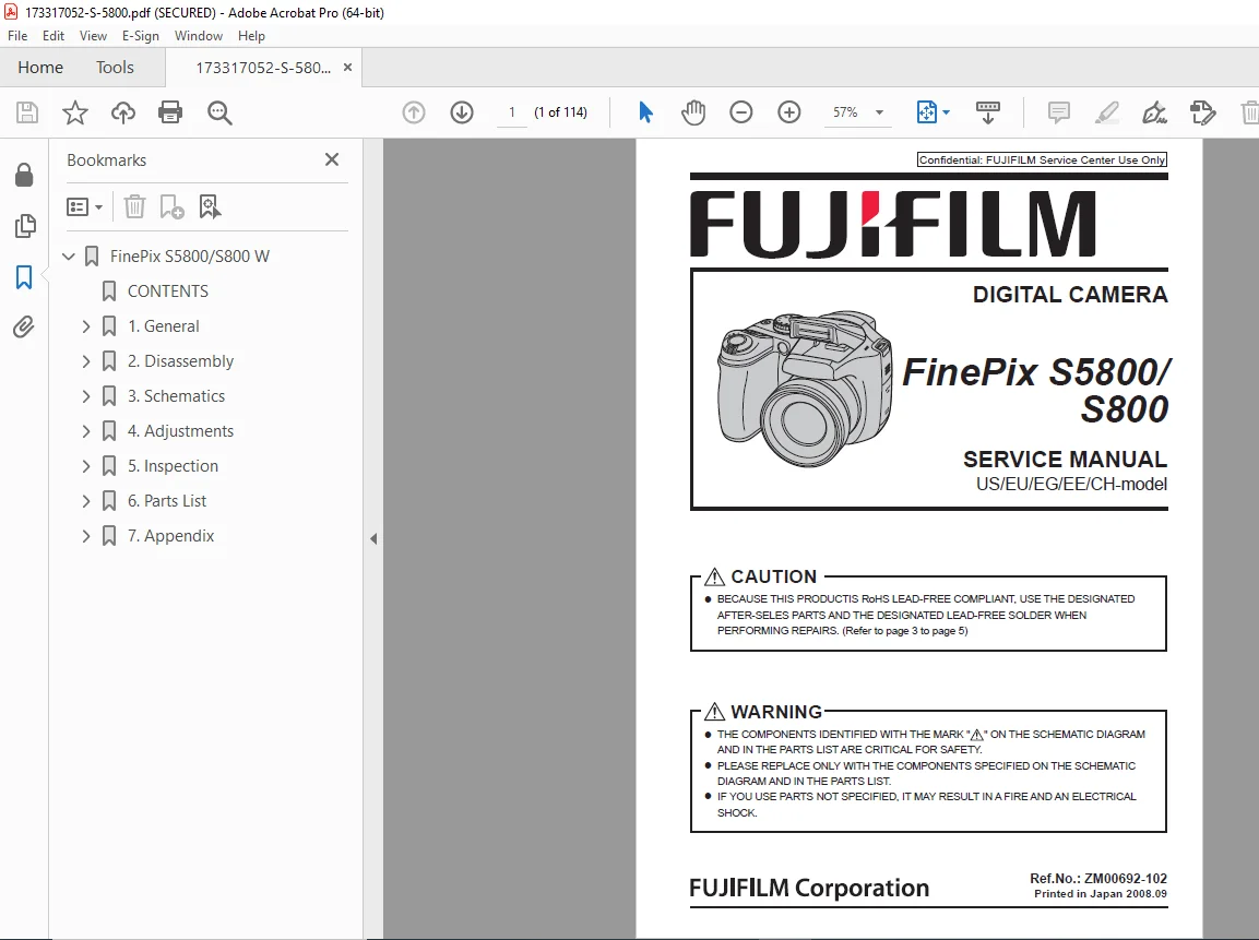
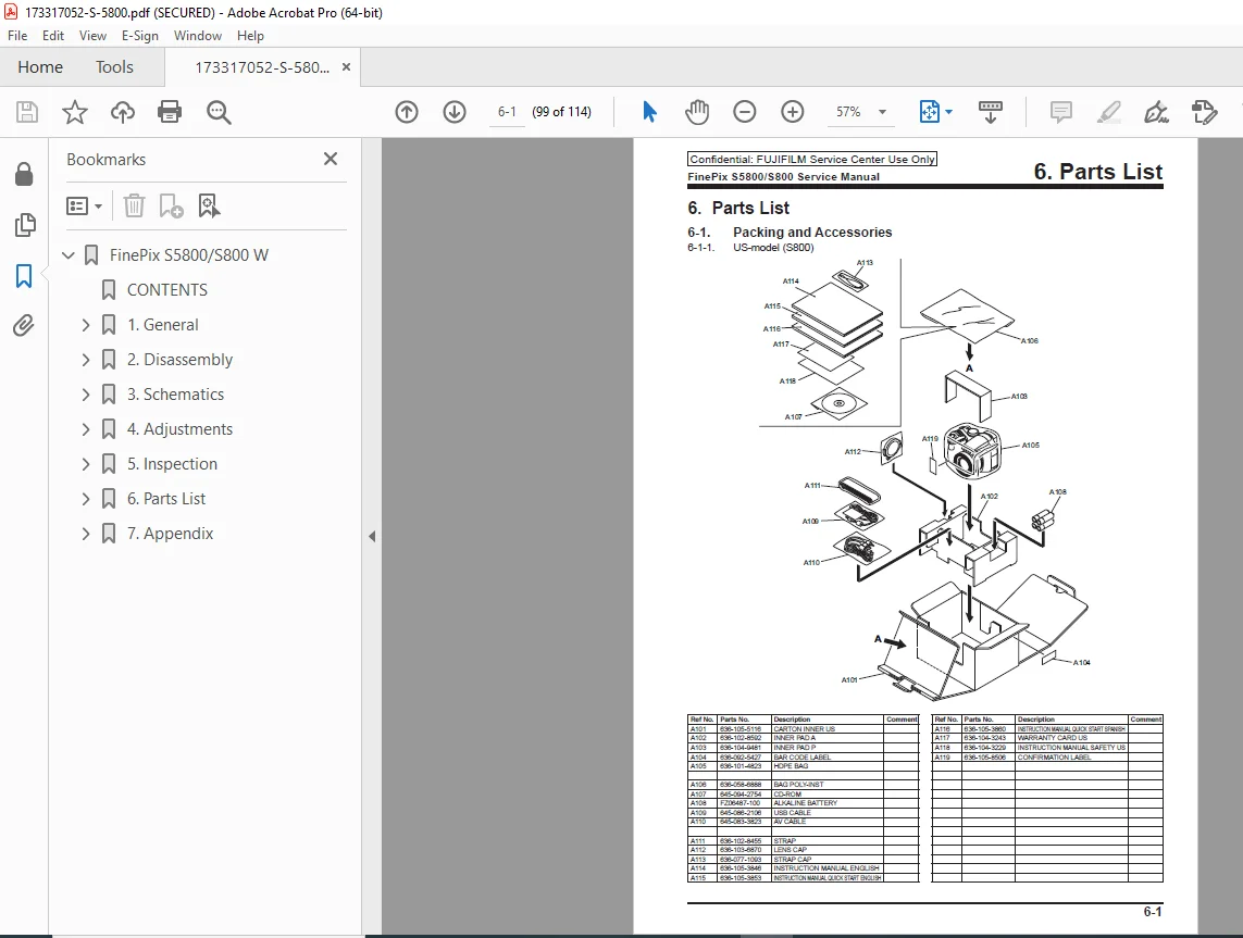
Fujifilm FinePix S5800 S800 Digital Camera Service Repair Manual PDF
Original price was: $95.00.$15.95Current price is: $15.95.
Complete factory service manual for Fujifilm FinePix S5800/S800 digital cameras. Covers all US/EU/EG/EE/CH models with detailed RoHS lead-free repair procedures, circuit schematics, disassembly instructions, and adjustment protocols. Essential technical documentation for professional camera repair technicians working on 8MP FinePix models with 10x optical zoom.
Description
Fujifilm FinePix S5800 S800 Digital Camera Service Repair Manual PDF DOWNLOAD
FILE DETAILS
| Detail | Information |
|---|---|
| Manual Name | FUJIFILM FinePix S5800/S800 Digital Camera Service Manual |
| Models Covered | FinePix S5800 (EU/EG/EE/CH models), S800 (US model) |
| Year | 2008 (Ref. ZM00692-102, Printed September 2008) |
| Pages | 114 pages |
| PDF Quality | High quality – professionally created with Adobe InDesign |
| Language | English |
| File Size | 9.1 MB |
DESCRIPTION
Professional Factory Service Manual for FUJIFILM FinePix S5800/S800 Digital Cameras
This comprehensive FUJIFILM FinePix S5800 S800 service repair manual provides complete factory-level technical documentation for professional technicians servicing these 8.0 megapixel digital cameras with Fujinon 10× optical zoom lenses.
Models Covered in This Service Manual:
- FinePix S5800 – EU/EG/EE/CH models
- FinePix S800 – US model
- All regional variants with complete specifications
Complete Manual Contents Include:
1. General Information (Section 1)
- Product specifications and technical data
- 8.0 megapixel 1/2.5-inch CCD system
- Fujinon 10× optical zoom lens (f=6.33-63.3mm, equivalent to 38-380mm)
- Storage media compatibility (Internal memory, xD-Picture Card, SD Memory Card)
- External component identification
- Technical terminology explanations
- Camera system architecture
2. Detailed Disassembly Procedures (Section 2)
- Internal component identification with photos
- Step-by-step rear construction removal
- LCD panel removal and replacement
- COMPL PWB,CP-1 disassembly instructions
- Side cabinet removal procedures
- Complete lens assembly disassembly
- Flash unit and EVF unit removal
- Front cabinet disassembly
- Spacer and sheet affixing locations
- Professional disassembly sequences with diagrams
3. Complete Circuit Schematics (Section 3)
- CCD circuit operation descriptions
- CP1 circuit operation details
- Power circuit diagrams
- Flash circuit schematics
- System control circuit diagrams
- Block diagrams for all major systems
- Overall connection diagrams
- Detailed circuit diagrams for:
- CA1 and CA2 blocks
- CCD block
- CP1 blocks (DMA, PWA, STA, SYA, TCA)
- Flash block
- Main/LCD driver block
- Power block
- Lens block
- System control block
- TB1 and TB2 blocks
- Mounted parts diagrams for all PWB assemblies
4. Adjustment and Calibration Procedures (Section 4)
- Pre-adjustment important points
- Image file handling protocols
- Adjustment software installation
- PC connection procedures for diagnostics
- MAIN PWB ASSY initialization
- Complete lens adjustment procedures
- Auto White Balance (AWB) adjustment
- CCD defect detection protocols
- CCD black defect detection
- Firmware update procedures
- Completion settings and verification
- Pattern box calibration methods
- Required measuring instruments
5. Inspection Procedures (Section 5)
- Required measuring equipment specifications
- Equipment connection diagrams
- Complete inspection protocols
- Factory settings documentation
- Quality control procedures
6. Comprehensive Parts List (Section 6)
- Packing and accessories for all models
- Mechanical block components (Block 1 & 2)
- Flash block parts
- Electrical components catalog
- Model-specific part variations
- Part numbers and specifications
7. Technical Updates (Section 7)
- List of related technical bulletins
- Service update notifications
Special RoHS Lead-Free Compliance Section:
- Complete lead-free soldering procedures
- Designated after-sales parts requirements
- Lead-free solder specifications (Sn96.5Ag3Cu0.5)
- Soldering iron temperature settings (220°C melting point)
- Safety procedures for RoHS-compliant repairs
- Flux and solder wire specifications
- European RoHS directive compliance details
Safety and Critical Component Information:
- Safety checkout procedures after repair
- Critical safety components identification
- High voltage warnings
- Fuse replacement specifications (2.5A 125V)
- Leakage current measurement protocols
- Unauthorized parts replacement warnings
Why This Manual is Essential:
This Fujifilm S5800 service manual and S800 repair documentation provides everything professional camera technicians need for complete diagnosis, repair, and calibration of these popular 8-megapixel bridge cameras. With detailed schematics, adjustment software descriptions, and comprehensive parts lists, you’ll have factory-level repair capabilities.
Perfect for professional camera repair shops, electronics technicians, and certified service centers working on Fujifilm FinePix digital camera repairs.
INSTANT DOWNLOAD – GET YOUR MANUAL NOW! Stop searching for repair information and get the official factory documentation immediately. Download this professional service manual and start repairing FinePix S5800/S800 cameras with confidence today!
This listing is optimized for search engines with natural keyword integration throughout the title, descriptions, and file details section.