
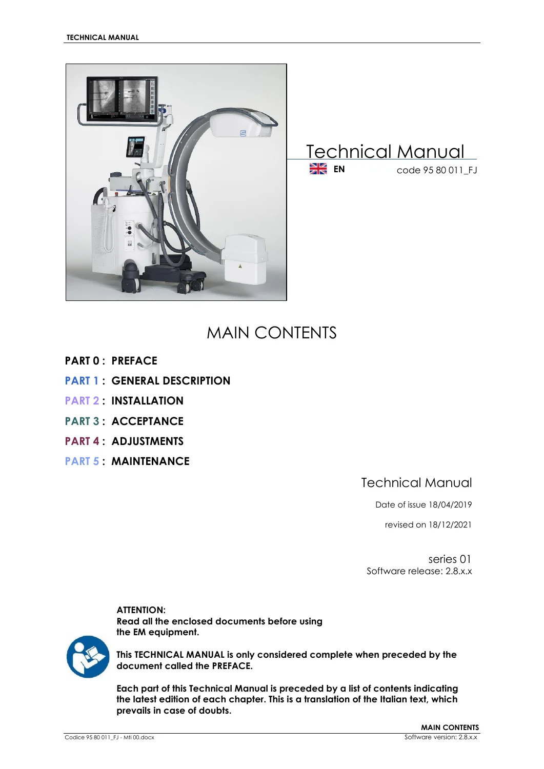
Fujifilm Visionary CS C-Arm Technical Manual PDF – Code 95 80 011_FJ Revised December 2021
Original price was: $39.95.$24.95Current price is: $24.95.
English technical manual code 95 80 011_FJ for the mobile C-arm (SF21, SR21, SR30 / ARCO FP-S), series 01, software 2.8.x. Covers description, installation, acceptance tests, generator and detector calibration, routine and extraordinary maintenance, and component replacement. Issued 18/04/2019, revised 18/12/2021.
Description
File Details
- Manual type: Technical Manual (service, installation, adjustment, and maintenance)
- Equipment: Mobile C-arm EM equipment, models SF21, SR21, and SR30 (station / video-processor identity ARCO FP-S / C-ARM FP-S)
- Language: English (translation of the Italian source text; installation and maintenance menus in the equipment software are English only)
- Page count: 324
- File format: PDF
- Document code: 95 80 011_FJ
- Series / software: series 01, software release 2.8.x
- Date of issue: 18/04/2019
- Revision date: 18/12/2021
The Fujifilm Visionary CS C-Arm Technical Manual PDF – Code 95 80 011_FJ Revised December 2021 is the service document used to install, accept, calibrate, and maintain this mobile flat-panel C-arm. The cover states that the technical manual is only considered complete when preceded by the separate Preface document. Each part opens with its own contents list showing the latest chapter edition.
Equipment and Configurations Covered
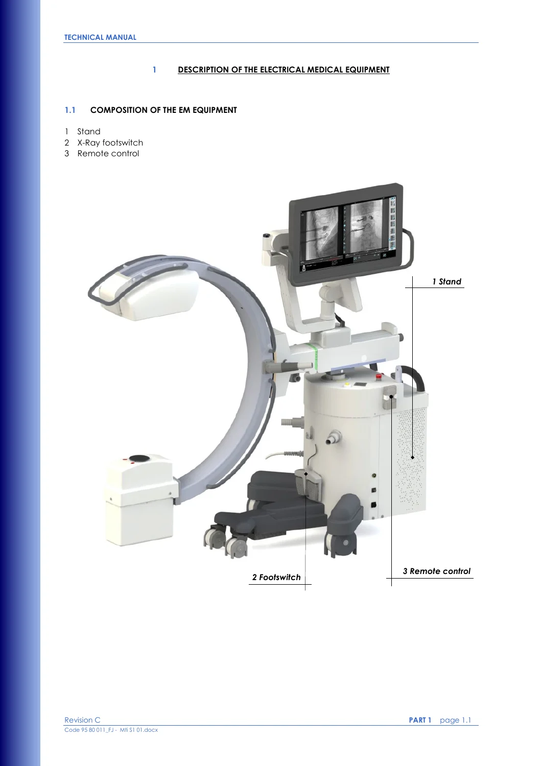
The stand, X-ray footswitch, and infrared remote control make up the electrical medical equipment. The stand carries the control panel, 27-inch dual-image touchscreen monitor, X-ray monoblock and collimator, flat panel detector, base unit with power supply and control electronics, motorized column, C-arm brakes (angle, rotation, longitudinal, and wig-wag), emergency stops, USB and Ethernet (DICOM) ports, HDMI auxiliary-monitor output, and optional NFC reader, laser localizers, and Dose Area Product meter.
Three hardware families share this Fujifilm Visionary CS C-Arm Technical Manual PDF – Code 95 80 011_FJ Revised December 2021:
- SF21 — monoblock I-40S 3,5 RF (4.0 kW), tube CEI OX/125-0612, foci 0.6 / 1.2 mm, stationary anode, Pixium 2121S-AU detector, 21 x 21 cm field
- SR21 — monoblock I-40R 15 RF or I-40R 15 RF AC (20 kW), tube IAE RTM70H, foci 0.3 / 0.6 mm, rotating anode 3000/3600 rpm, PaxScan 2121DXV detector, 21 x 21 cm field
- SR30 — same rotating-anode monoblock family as SR21 with PaxScan 3030DXV detector and 30 x 30 cm field
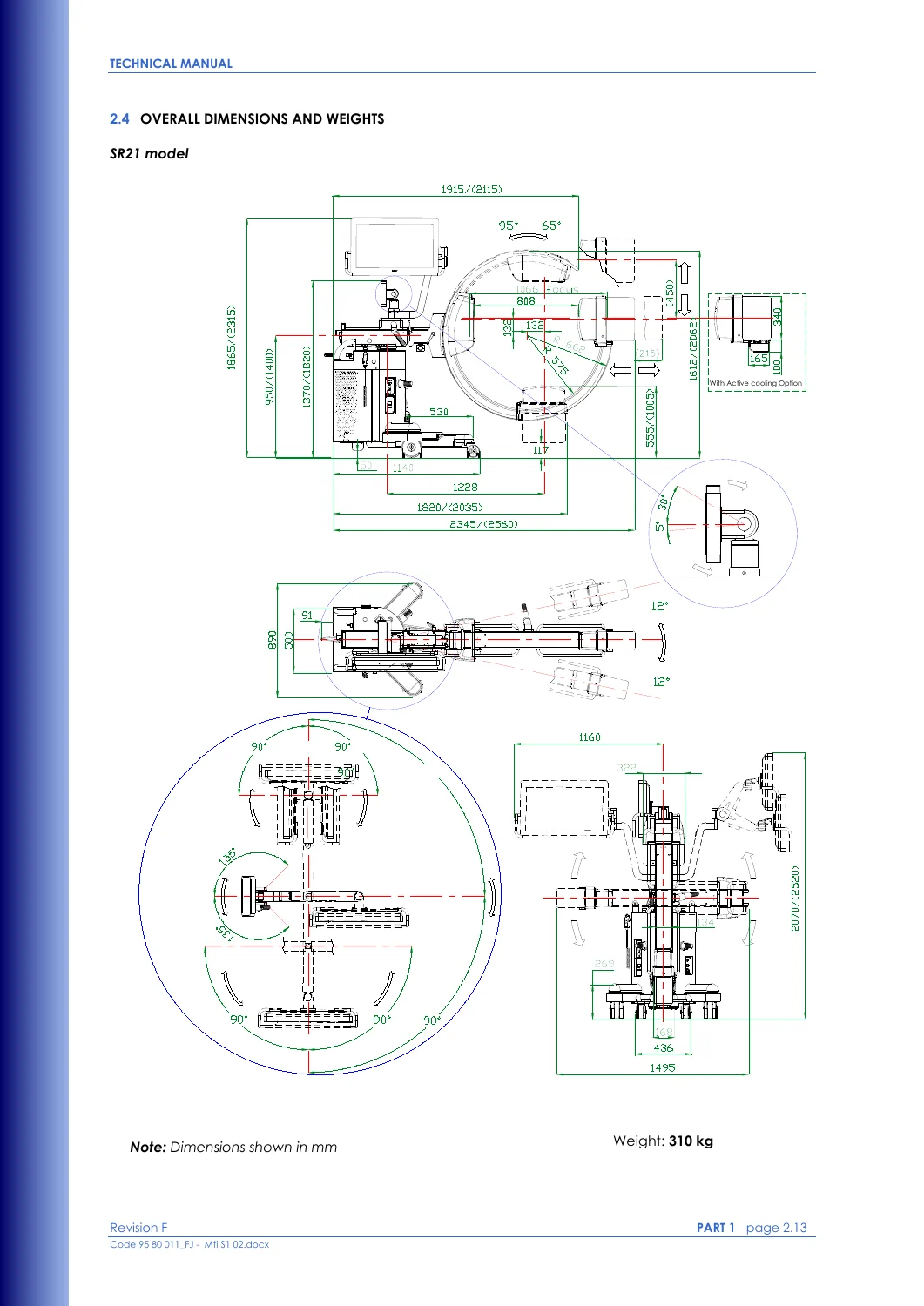
Passive or active monoblock cooling is specified for the SR21/SR30 path. Motorized C-arm angulation, wireless footswitch, injector interface, room-light control, and remote emergency breaker appear as options. Nominal stand weight on the dimension drawings is 310 kg.
Imaging Modes and Generator Limits
Acquisition modes documented in the technical data and later setup chapters are Low Dose Fluoroscopy, High Quality Fluoroscopy, Digital radiography (Snapshot), and optional Road Mapping and DSA fluoroscopy. The generator (code IRI.37.203.001) oscillates at 40 kHz, reaches 120 kVp, supplies up to 50 mA in pulsed fluoroscopy at 100 kV, 6 mA in continuous fluoroscopy at 100 kV, and 100 mA maximum in radiography (5 kW class at 50 mA / 100 kV / 0.1 s on the generator table). Fluoroscopy and snapshot mA curves are plotted separately for the OX125 (SF21) and RTM70 (SR21/SR30) tubes at ≤15 fps and 30 fps.
Mechanical ranges used during install and acceptance include 450 mm motorized vertical stroke at 1 cm/s, 215 mm horizontal stroke, ±12° wig-wag, ±275° rotation about the horizontal axis, and 160° C-arm sliding. Source-to-image distances are 1080 mm (SF21/SR30) and 1066 mm (SR21). Mains versions are 230 Vac ±10% or 120 Vac ±10%, 50/60 Hz, with Type D two-pole magnetothermal breakers (10 A on 230 V, 16 A on 120 V).
Chapters Covered
- Part 0 — Preface (referenced as a required companion document)
- Part 1 — General Description: composition of the EM equipment and stand callouts; applications and modes; safety (mechanical, electrical, equipotential earth, class 1M laser localizers, ionizing-radiation protection, contra-indications); emergency buttons, software hang-up/crash recovery, and system-failure planning; residual risks and WEEE scrapping notes; symbols; full control-panel status and alarm message tables; EMC emissions, immunity, and recommended RF separation distances; technical data (device class, mechanical/electrical data, imaging system, exposure-mode pointers, fuses, overall dimensions and weights for SF21/SR21/SR30, focal-spot position drawings, fluoroscopy and snapshot mA curves); storage and handling
- Part 2 — Installation: installation procedure; unpacking cardboard or wooden packaging; mechanical installation of the monitor support arm and monitor; electrical connectors, wired or wireless footswitch, peripherals, and mains; video-processor setup (login, general and auto-delete settings, unit configuration including optional active cooling and motion control, exam and DSA parameters, image processing, exam list management); DICOM settings and services (Store, Worklist, Media, Storage Commitment, MPPS, Radiation Dose Structured Report, Query/Retrieve), devices, spooler, and print annotation; DRC group and editor; user accounts; fixed strings; motion-control and room-light setup; annexes for monitor configuration, touch-screen calibration, Windows administrator login, Ethernet and optional wireless USB networking, online manuals, software version, video-processor backup, opening-screen logo; X-ray tube seasoning for SR21/SR30 and SF21
- Part 3 — Acceptance: cable and connector checks; mechanical checks of C-arm motions, brakes, column, wheels, monoblock, monitor arm, and anti-scatter grid; electrical and efficiency checks including login, emergency stop, low-dose and high-quality fluoroscopy, radiography timing limits, DAP, and collimator fields; image-quality check; printable Test Sheet; annex for fluoroscopy dose intensity, automatic dose control, grey scale, spatial resolution, noise, low-contrast resolution, DAP, and Air Kerma indications
- Part 4 — Adjustments: X-ray generator menus (General set-kV, pulsed fluoro filament, continuous fluoro filament, Snapshot filament, DAP / Air-Kerma / Auto kV); checking kV and mA on SR21/SR30 versus SF21; collimator shutter and square-field centering; laser centering on monoblock and FPD; column up/down speed; flat-panel detector calibration (exposure values, fluoroscopy and radiography maps for 3030, 2121, and Pixium 2121S-AU); potentiometer, LED, and fuse lists
- Part 5 — Maintenance: daily/weekly and six-monthly checks; cleaning pointers to the User Manual; troubleshooting tables keyed to control-panel messages; component-replacement matrix; restoring the video-processor hard disk; upgrading CTBK-HW (CBTK-HW) and SYSTEMA DRF-S software; monitor adjustment; optional wireless room-light control; spare-parts list; scrapping precautions; fitting and removing covers, monoblock, collimator, DAP, FPD, laser/grid unit, parking brakes, wheel chains, C-arm bearings, video processor, CTBK-HW and ASAC 01 boards, control panel, inverter, and mains cable; annexes for backup-disk creation, contrast-medium injector interface, remote emergency breaker, external signal lamp, image and exam import/export, motherboard backup-battery replacement, Trotter W wireless image transmission, and SF21 defective-pixel correction
Taken as a whole, this Fujifilm Visionary CS C-Arm Technical Manual PDF – Code 95 80 011_FJ Revised December 2021 is the technician-facing companion to the User Manual. It tells a trained fitter how the stand is put together, how mains, DICOM, and options are commissioned, which acceptance measurements must be logged on the Test Sheet, how generator curves and detector maps are rebuilt after a part change, and how boards, the monoblock, the FPD, and the video processor are swapped without leaving the system uncalibrated.
Safety, Alarms, and Electromagnetic Compatibility
Part 1 collects the mechanical and electrical warnings that apply on the shop floor and in the theatre: parking brakes after positioning, no use in explosive or oxygen-rich atmospheres, Class I earthing, equipotential bonding of the patient bed with a Multi-Contact POAG-K4 or POAG-K6 lead, class 1M laser diodes at 635 nm, and ALARA collimation and distance rules. Emergency hardware is mapped: the central button kills the entire EM equipment; the two lateral buttons stop only motorized column (and, where fitted, angulation) motion. Software hang-up is recovered by key-off for about 10 seconds; an application crash returns to the LOGIN page after an automatic reboot.
Long status and alarm tables list READY through FLUOROSCOPY DSA, RAD PREPARATION, grid insert/remove interlocks, fluoroscopy time-outs (5 minutes and 10 minutes accumulated), MAX RADIOGRAPHY TIME (970 ms), thermal and heat-unit limits, generator faults (filament, kV unbalanced / max / min, mA too low or high, NO RX), collimator offline, DAP fault, cooling pump and fan faults, and the motor-driver family (overcurrent, overvoltage, encoder, CAN bus, position lost). EMC declarations follow EN 60601-1-2 4th edition: CISPR 11 Group 1 Class A emissions and the matching immunity levels, plus a recommended 0.3 m separation table for portable RF transmitters.
IMAGES PREVIEW
Installation, DICOM, and Exam Setup
Part 2 walks from pallet and ramp unpacking through monitor-arm assembly, then documents every connector on the stand: footswitch, injector, equipotential earth, Ethernet, HDMI, USB, remote emergency (motorized-angulation option), and the general circuit breaker. Video-processor setup is the longest installation chapter. After Administrator or Advanced login it covers auto-delete policy, unit identity (institution, station name C-ARM FP-S, model ARCO FP-S), optional active cooling and motion control, programmable exam and DSA parameters, recursive-filter and DRC image processing, and the full DICOM service set used to talk to Worklist, Store, Print, MPPS, Storage Commitment, Dose Structured Report, and Query/Retrieve peers. Network annexes give Ethernet physical notes, Windows settings, a connection test, and an optional wireless USB adapter path. Tube seasoning procedures for both the rotating-anode SR21/SR30 path and the SF21 path close the installation part for systems that have sat unused for more than two months.
Calibration After Service
Part 4 assumes factory adjustment is already done and is used after component replacement or during scheduled work. Generator calibration is split across five on-screen menus: set-kV correction at 40 kV and 100 kV set points (80–120% trim, 1000 = no correction), filament current for pulsed and continuous fluoroscopy, Snapshot filament current, and DAP / Air-Kerma / Auto kV factors. Separate kV/mA verification paths exist for SR21/SR30 and SF21. Collimator work covers shutter and iris centering; laser work covers both monoblock and detector heads; column work sets the specified 1 cm/s travel. Detector calibration chapters give exposure-finding steps and then fluoroscopy and radiography map procedures for PaxScan 3030DXV, PaxScan 2121DXV, and Pixium 2121S-AU, with an SF21-only statistics view and a later Part 5 annex for editing defective pixels in Gain and Defect Map files.
Maintenance, Fault Finding, and Parts
Routine maintenance points daily and weekly inspections to the User Manual and requires a full Acceptance Test every six months, recorded on the Test Sheet reprinted at the back of this file. Extraordinary maintenance opens with a numbered troubleshooting table that ties symptoms (dead stand, blank monitor, FILAMENT FAULT, NO RX, collimator fault, DAP fault, stuck pedals, thermal cut-out) to probable causes and first actions such as checking TB2 fuses F2–F5, resetting the magnetothermal breaker, or replacing the monoblock or generator. A replacement matrix then states which calibration must follow a new video processor, FPD, monoblock/generator, collimator, CTBK-HW board, laser, ASAC 01 board, or DAP. Mechanical chapters show cover removal and the physical swap of the monoblock, collimator, DAP, FPD, parking brakes, wheel chains, C-arm bearings, inverter, control panel, and mains cable (replacement cable code 550 95 005). Software chapters cover CTBK-HW firmware and SYSTEMA DRF-S application updates plus restoration of the video-processor disks from the factory backup USB stored inside the stand. The motherboard buffer battery is specified for replacement every three years.
Use This Manual on the Bench and at Handover
With the Fujifilm Visionary CS C-Arm Technical Manual PDF – Code 95 80 011_FJ Revised December 2021 a qualified technician can unpack and assemble the stand, commission 120 V or 230 V mains, load exam and DICOM configuration, run the coded acceptance sequence (A/B/C/D checks plus dose and image-quality annexes), rebuild generator curves and detector maps after a tube, inverter, or FPD change, and work through the published alarm list instead of guessing at a frozen control panel. Using the printed kV/mA limits, radiography timing windows (for example 654–885 ms at 40 kV / 50 mAs on 230 V), column speed of 1 cm/s, and heat-capacity figures keeps dose display, image quality, and thermal protection inside the values the equipment was designed around. The file is supplied as an instant PDF download after payment — no shipping, readable on any device, and printable for the theatre workshop or the acceptance folder. Pair it with the Preface and the User Manual referenced throughout when a complete document set is required.

Reviews
There are no reviews yet.