
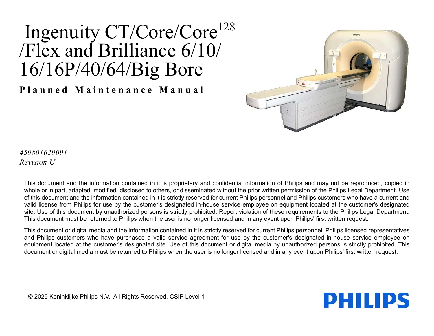
Philips Ingenuity CT Core128 Flex Brilliance 6-64 Big Bore Planned Maintenance Manual Rev U
Original price was: $34.95.$19.95Current price is: $19.95.
Philips planned maintenance manual 459801629091 Rev U for Ingenuity CT, Core, Core128, Flex and Brilliance 6/10/16/16P/40/64/Big Bore systems, covering quarterly PM tasks, lubrication, slip rings, optics, and final IQ checks.
Description
File Details
- Manual type: Planned Maintenance Manual
- Brand / systems: Philips Ingenuity CT, Core, Core128, Flex and Brilliance 6/10/16/16P/40/64/Big Bore
- Document number: 459801629091
- Revision: U (September 2025)
- Language: English
- Page count: 218
- File format: PDF
- Classification: CSIP Level 1
What This Planned Maintenance Manual Covers
The Philips Ingenuity CT Core128 Flex Brilliance 6-64 Big Bore Planned Maintenance Manual Rev U is the field PM guide for the listed Ingenuity and Brilliance CT platforms. It tells a trained service person what to inspect, clean, lubricate, measure, and record on a usage-based visit schedule. Cover removal, full repair and replacement, and detailed calibration methods are pointed to the matching gantry, patient-support, image-quality, and calibration manuals rather than repeated here.
Average usage is defined as about 200,000 scan seconds per year. High usage is more than 300,000 scan seconds; low usage is 100,000 scan seconds or less. Table 1-1 maps each task to PM1 through PM7 so a site can run four quarterly visits, combine visits, or add extra half-day calls on high-usage scanners. PM7 (collimator compensator / wedge crack detection) must still run at least once each quarter, locally or remotely.
Chapters Covered
- Section 1 Introduction — prerequisites, power up/down references, gantry and patient-support cover notes, activity reporting, PM frequency, and the planned maintenance task table
- Section 2 Preliminary Checks — basic helical-scan and door / X-ray-on checks, CT Box motion, software and counter records, collimator compensator / wedge maintenance, disk cleanup, ceiling-mounted CCT arm monitor bracket inspection
- Section 3 Patient Support Planned Maintenance — vertical safety support installation, external checks (visual, foot switch, tape switch, anchor torque), interior inspection, scissors inspection, bariatric option PM, lubrication, final checks and reassembly, accessories check
- Section 4 Gantry Planned Maintenance — external checks and labels, interior cleaning, front-cover inspection, fans and intake filters, X-ray tube and connectors, heat exchanger and isolators, dual-pot and main drive belts, cables, rotor, protective-earth measurements, UDMS 7-fan cleaning, main-bearing lubrication, slip-ring maintenance, optics inspection and cleaning, collimator verification, reassembly
- Section 5 Common Console Planned Maintenance — console cleaning, host rack / CIRS exterior, host / CIRS interior and GPU cleaning, motherboard CMOS battery replacement, paint touch-up, UPS inspect and test
- Section 6 OS Patch Update — points to 300015712531; not applicable to Big Bore
- Section 7 Planned Maintenance Final Checks — calibration and IQ tests, system backup, intercom check
- Appendix A Visual Collimator Compensator Inspection (optional)
- Appendix B Paint Touch-up (optional)
- Appendix C Patient Support Subframe Quick Release
- Appendix D Planned Maintenance Manual Activity Record
Taken together, the chapters walk a visit from first functional checks through mechanical and electrical PM, then console work and the software tests that close the scanner for clinical use. Estimated task times in Table 1-1 range from a few minutes (intercom, accessories) to about 60 minutes for gantry interior cleaning or slip-ring work, 80 minutes for calibration and IQ tests, and 180 minutes for the three-year bariatric patient-support option.
Patient Support, Safety Bracing, and Lubrication
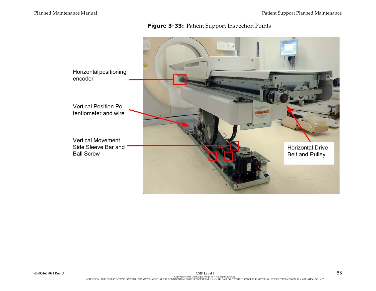
Section 3 starts with crush-hazard warnings and the vertical support brace that must be installed whenever anyone works under the scissors. External work covers loose or damaged covers, standard and multi-function foot switches, tape switches, and an anchor torque check. Interior inspection looks at hardware, cables, the drive belt, the vertical encoder O-ring belt, vacuum interior condition, horizontal drive linkage, bariatric gas spring, brakes, ball screw, and tape on the vertical-drive spring.
Scissors inspection lists a steel scale, flashlight, 1-1/2 in socket, 5/16 in hex key, 3–125 ft-lbs (4–169 Nm) torque wrench, and Loctite 242. Lubrication is split across the vertical ball screw, vertical slide rails, linear rail bearings on non-bariatric tables, and table-top rails and rollers. Final checks return covers from the service position, prove motion, clean the exterior, and optionally touch up paint. Accessories are checked on the PM1 visit.
Gantry Interior, Slip Rings, Optics, and Grounding
Gantry work begins with high-voltage warnings, loose-hardware and caution-label checks (laser radiation labels and the patient max-load warning), control-panel function, laser inspection, and E-stop positions. Front-cover inspection differs by platform: Ingenuity and Big Bore use torque-seal review and 9 ft-lbs (12.2 Nm) retightening if the seal is broken; Brilliance 6/10/16/16P/40/64 inspects the fiberglass-to-hinge-beam bond.
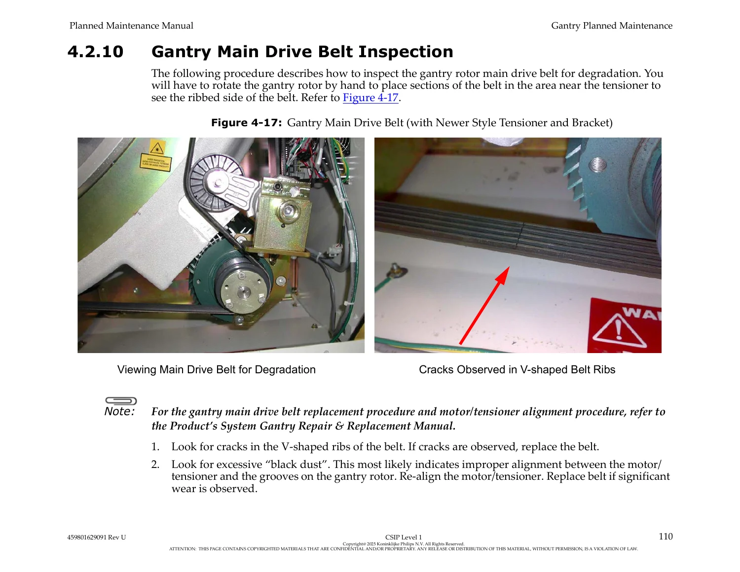
Tube inspection waits at least 10 minutes after wall-box isolation, then looks for oil at the anode and cathode HV connectors, housing damage that could impair radiation protection, fasteners, cables, hoses, and couplings. Yearly connector service uses silicone paste p/n 131 2501 48202. Heat-exchanger fins are vacuumed; rubber isolators on MRC600, MRC800, or MRC880 cooling-unit pumps are inspected. Dual-pot belt deflection is given as about 1/8 in to 1/4 in (0.32 to 0.63 cm). The main drive belt is inspected for cracked V-ribs and black dust that can indicate motor/tensioner misalignment.
Protective-earth measurements in Table 4-2 require a digital multimeter on a low-resistance range. After subtracting lead resistance, each path must fall between 0 and 0.3 ohms: wall-box earth ground to gantry ground block, gantry ground block to gantry rotor, and gantry rotor to the patient-support ground stud. Lockout/tagout at the wall box is mandatory.
Main-bearing lubrication is annual. Ingenuity Core/Core128/CT, Ingenuity Flex, and Brilliance 6–64 use Mobilgrease 28 (p/n 4535 663 61061) with a total of no more than 9.5 cc per year. Big Bore uses Asonic Gly 32 (p/n 4535 673 09541). Slip-ring inspection and cleaning are due every six months or at 2.5 million revolutions since the last lubrication. Big Bore slip rings serial number 001 to 114 have their own brush-block removal, cleaning, and lubrication path. Optics inspection every six months covers visible and invisible optical data links; Class 3B invisible laser radiation is present with the rear cover off and the interlock defeated. Invisible optical power is adequate at ≥ 75 uW on Ingenuity and ≥ 100 uW on Brilliance 64 when measured with the Moog Velocity Laser Power Measurement Kit (p/n 4535 675 60151). Collimator A-plane opening is verified every six months with the diagnostic tool (preferred on software v3.5 or later) or with hex keys.
IMAGES PREVIEW
Console, Host, GPU, UPS, and Close-Out Tests
Common-console PM uses a mild non-abrasive solvent applied to a cloth, an anti-static vacuum (TC206), and canned air. Host / CIRS interior work includes GPU cards with locking tabs, side-case screws, or panel screws. Host and CIRS motherboard CMOS batteries are on a two-year interval. UPS units are cleaned, inspected, and tested. OS patch status is checked on Ingenuity and Brilliance 64 per manual 300015712531; the patch path does not apply to Big Bore.
Section 7 requires filament Pass 2 and tube-output calibration each visit (minimum twice per year), conditional air calibration after more than seven days, beam-path cleaning, or concentric rings on QA/constancy/IQ, plus DDOM and ZDOM dose-modulation checks at least twice per year. A system backup and an intercom check finish the visit. Actions must be recorded in real time on the Activity Record, in the PA tool (SAP MP1), or in ProntoForms and attached to the service work order.
Who This Manual Is For
The document is written for trained personnel who already know the matching safety manual, lockout/tagout, ESD practice, and radiation-protection rules (including NCRP 102 and related grounding and survey notes in the front matter). A password notice restricts service-utility passwords to the utilities described in the manual. Compensator Analyzer is installed from Zeppelin (InCenter) before compensator work on older software; Refresh software systems use Beam and DMS check in Quality Assurance or the ATP Physics ResultAndHistoryViewer.
Use This Manual On the Bench and On Site
The Philips Ingenuity CT Core128 Flex Brilliance 6-64 Big Bore Planned Maintenance Manual Rev U supports scheduled PM on the listed scanners: usage-based visit planning, compensator crack screening, orphaned-study and ZDOM cleanup, patient-support bracing and lubrication, gantry cleaning and belt checks, slip-ring and optical-link service, protective-earth verification, console and UPS care, and the calibration / IQ sequence that returns the room to clinical scanning. Following the printed intervals, lubricant part numbers, torque and resistance limits, and laser-power thresholds keeps wear items from becoming unplanned downtime and keeps dose-related collimator and IQ checks inside specification.
Download the PDF immediately after purchase. Open it on a laptop, tablet, or shop computer, print the Activity Record and task pages you need for the visit, and keep the file with the rest of the site documentation. No shipment and no wait for a paper binder.
Reviews
There are no reviews yet.