
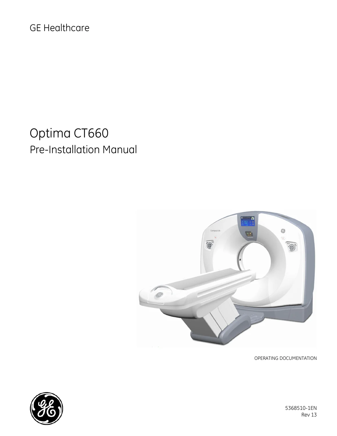
GE Optima CT660 CT Scanner Pre-Installation Manual – Direction 5368510-1EN Rev 13
Original price was: $39.95.$24.95Current price is: $24.95.
Comprehensive pre-installation site planning manual for the GE Healthcare Optima CT660 computed tomography system. Includes complete architectural layout dimensions, floor loading and structural anchoring requirements, HVAC thermal output ratings, electrical service feeds, PDU interconnect diagrams, and regulatory service clearances across all compatible patient table configurations.
Description
Comprehensive Facility Planning for the GE Optima CT660 CT Scanner
Executing a flawless clinical deployment of the GE Optima CT660 computed tomography scanner demands rigorous adherence to manufacturer site-readiness specifications. The GE Optima CT660 CT Scanner Pre-Installation Manual – Direction 5368510-1EN Rev 13 serves as the definitive engineering and architectural reference for hospital project managers, facility planners, general contractors, licensed electrical contractors, and biomedical engineers. This manual establishes every physical, structural, environmental, electrical, and regulatory requirement necessary to convert a raw clinical footprint into a fully certified diagnostic imaging suite, preventing costly site modifications, installation delays, or hardware damage.
File Details
| Field | Value |
|---|---|
| Manual Type | Pre-Installation Manual (Site Planning and Architectural Guidelines) |
| Equipment Brand & Model | GE Healthcare Optima CT660 CT Scanner |
| Document Direction Number | 5368510-1EN |
| Publication Revision & Date | Revision 13 (February 07, 2018) |
| File Format | Direct Digital PDF |
| Total Page Count | 156 pages |
| Language | English |
Structural Engineering, Floor Loading, and Anchoring Criteria
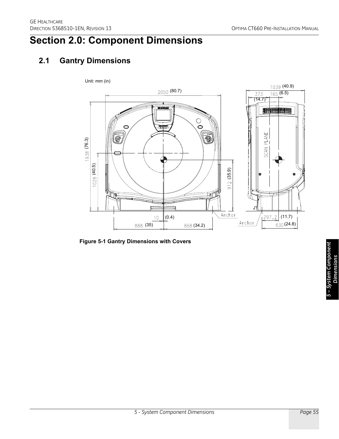
The GE Optima CT660 CT Scanner Pre-Installation Manual specifies strict structural parameters to support system weight dynamics and maintain laser alignment precision during scanning. The gantry alone weighs 1810 kg (3990 lb) with a concentrated downward load distributed over four 64 mm (2.5-inch) leveling pads. Total scan room loads escalate substantially when pairing the gantry with the VT2000 table (732 kg / 1613 lb with 227 kg / 500 lb patient load), VT2000x table (815 kg / 1797 lb with 306 kg / 675 lb patient load), GT1700V table (672 kg / 1481 lb with 227 kg patient load), or Lite table (525 kg / 1157 lb with 205 kg / 450 lb patient load).
Solid concrete slab construction requires a minimum compressive strength of f’c = 2500 psi (1.7 x 10^7 Pa) after 28 days curing time, with a minimum slab thickness of 102 mm (4.0 inches) for the gantry and standard tables (110 mm / 4-1/3 inches for the Lite table). Maximum allowable floor levelness variance is strictly 6 mm over a 3048 mm run (1/4 inch over 10 feet), with floor shims expressly prohibited. Detailed engineering schematics guide the positioning of GE-supplied Hilti Kwik Bolt mechanical anchors (P/N 2106573, P/N 5487992-2, and P/N 2106573-3), specifying minimum edge clearances of 125 mm to 160 mm away from floor joints and torque values of 54 N-m (40 ft-lbf) to 75 N-m (55 ft-lbf). Vibration criteria are established across the gantry resonance band (8–14 Hz) and patient table band (2–10 Hz) against AISC and ISO Class A (VC-A) and Class B (VC-B) limits.
Electrical Power, PDU Distribution, and Interconnection Architecture
Proper electrical provisioning is critical to energize the system. The GE Optima CT660 utilizes a dedicated Power Distribution Unit (PDU)—the solitary power entry point for all subsystems. Input power configurations require a 3-phase, 4-wire solidly grounded Wye or Delta feed operating across nominal supply ranges of 200–240 VAC or 380–480 VAC at 50/60 Hz +/-3 Hz. Power demands are fully detailed for the 100 kVA standard configuration (peak momentary demand 100 kVA at 0.85 PF for 140 kV / 515 mA technique; 20 kVA average effective demand; 5 kVA idle demand), as well as dedicated 75 kVA and 50 kVA regional options. Source regulation must remain within 6% total impedance.
The manual provides explicit wire sizing tables for feeder runs from the substation to the wall-mounted A1 emergency disconnect panel (featuring “Lock-Out/Tag-Out” provisions, undervoltage release, and proximity within 10 m / 32 ft of the PDU), as well as sub-feeder sizing from A1 to the PDU cabinet. Grounding specifications require a continuous, dedicated 1/0 AWG (55 mm²) insulated copper ground wire run through rigid steel conduit, with resistance under 0.5 ohm to facility earth ground (under 2 ohms total). Full interconnection schematics detail cable runs, UL ratings, pull diameters, and connector sizes for standard cable set 5444556 and long run option 5444556-2, along with TS6 terminal blocks for scan room door interlocks and x-ray warning indicators.
HVAC, Thermal Output, EMI Isolation, and Suite Clearances
Continuous thermal regulation protects sensitive digital detectors, DAS hardware, and x-ray tubes. The scan room requires an HVAC capacity capable of handling up to 23,130 BTU/hr (6,780 W) of heat rejection with standard tables, while total system cooling must manage 26,330 BTU/hr (7,720 W). Scan room and control room ambient temperatures must remain strictly between 18°C and 26°C (64°F to 79°F, recommended 22°C / 72°F) with relative non-condensing humidity between 30% and 60%. Ducting and diffuser layouts illustrate optimal airflow past gantry bottom intake grilles and top exhaust vents.
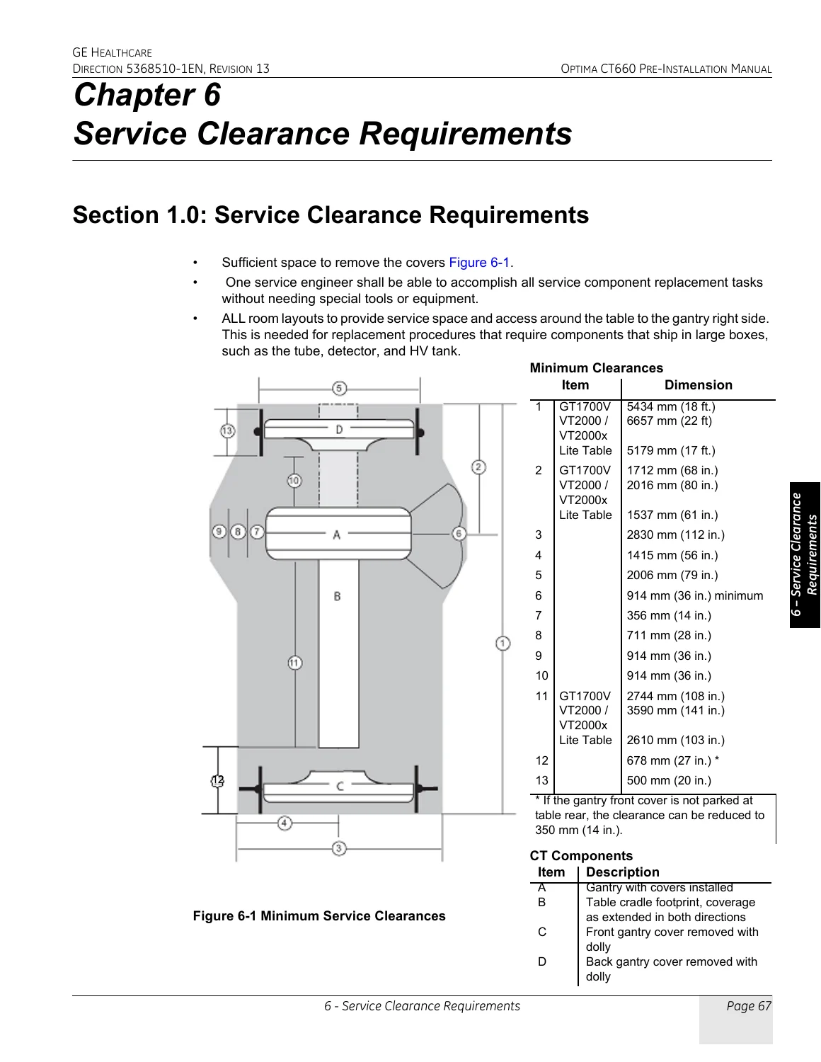
Clearance maps govern code compliance (NEC, OSHA 29 CFR 1910, NFPA 70E, NFPA 101, ADA) across Condition 1 (914 mm / 36 in), Condition 2 (1067 mm / 42 in), and Condition 3 (1249 mm / 48 in) working boundaries. Standard minimum scan room dimensions are defined: 5563 mm x 3327 mm (18 ft 3 in x 10 ft 11 in) for the GT1700V table; 6223 mm x 3327 mm (20 ft 5 in x 10 ft 11 in) for VT2000/VT2000x tables; and 5377 mm x 3320 mm (17 ft 8 in x 10 ft 11 in) for the Lite table. Mathematical modeling is provided for Short Footprint cradle limits when adapting installations to compact suites. Safe transit, rigging, and elevator limits prevent chassis distortion, strictly forbidding lifting the gantry by transport dollies or forklifts.
Chapters Covered
- Chapter 1 – Introduction: Section 1.0: What is Pre-Installation?; Section 2.0: What is Pre-Installation Work?; Section 3.0: Pre-Installation Tools; Section 4.0: Customer Pre-Installation Tasks
- Chapter 2 – Installation Types: Section 1.0: Determining Your Installation Type (Typical Installations, Full Construction Site with Completed Radiology Area, Full Construction Site with Limited Delivery Access, Relocatable Building Installations, Upgrade Installations, Quick Installations, Two-Step Temporary Installations)
- Chapter 3 – System Siting Requirements: Section 1.0: System Siting Requirements; Section 2.0: Customer System Siting Requirements (Regulatory, Electrical, Structural, Air/Dust Quality, Finished Floors, Finished Walls, Radiation Protection, Environmental, Clearances, Chemical Contamination, Delivery); Section 3.0: Site Readiness
- Chapter 4 – Regulatory Requirements: Section 1.0: Regulatory Clearances (Regulations, Clearance Requirements, Condition 1/2/3 References, Minimum Regulatory Workspace Clearances by Major Subsystem, How to Measure, NEC Conduit and Duct Fill Rate); Section 2.0: Terms and Definitions
- Chapter 5 – System Component Dimensions: Section 1.0: Minimum Operating Clearances (Ceiling Pedestal Mount Installation, Injector Control Installation, System Operational Clearances); Section 2.0: Component Dimensions (Gantry, Lite Table, GT1700V Table, VT2000/VT2000x Table, Power Distribution Unit, Operator Console, Freedom Workspace Table)
- Chapter 6 – Service Clearance Requirements: Section 1.0: Service Clearance Requirements (Gantry Service Clearance, Boom Assembly Clearance); Section 2.0: Service Clearances for Single Service Engineer (Cover Removal, PDU, Console, Storage Cabinet Inventory)
- Chapter 7 – Room Sizes: Section 1.0: Room Dimensions (Minimum Room Size Table); Section 2.0: Minimum Room Layouts; Section 3.0: Short Footprint Considerations (Cradle Limitation Calculations); Section 4.0: Control Room Considerations; Section 5.0: Patient Environment
- Chapter 8 – Structural and Mounting Requirements: Section 1.0: Overview; Section 2.0: Ceiling Requirements (Mavig Pedestal Mounting Plate, Electrical Box); Section 3.0: Minimum Floor Requirements (Floor Levelness Specifications, Measuring with Template, Scan Window, Floor Vibration Curves, Floor Strength); Section 4.0: Floor Loading and Component Weights; Section 5.0: GE-Supplied Anchoring (Hilti Bolt Specs, Torque, Embedment); Section 6.0: Seismic Mounting (Centers of Gravity for Gantry, Tables, PDU, Console)
- Chapter 9 – Environmental Requirements: Section 1.0: Temperature and Humidity Specifications; Section 2.0: Cooling Requirements (Heat Output Tables); Section 3.0: Altitude Limits; Section 4.0: Electro-Magnetic Interference (EMI Envelopes); Section 5.0: Electro-Magnetic Compatibility (IEC 60601-1-2 Compliance); Section 6.0: System Component Noise Levels
- Chapter 10 – Radiation Protection Requirements: Section 1.0: Shielding Requirements (Scatter Surveys, Iso-Contour Lines, Exposure Technique Scaling Factors)
- Chapter 11 – Network Requirements: Section 1.0: Network Connections (Broadband 100BASE-TX/1000BASE-T, RJ45 Drops); Section 2.0: Customer Broadband Responsibilities (InSite VPN, Static Routing)
- Chapter 12 – Power Requirements: Section 1.0: Introduction; Section 2.0: System Input Power (100kVA Standard, 75kVA Option, 50kVA Option, Regulation, Phase Imbalance, Grounding); Section 3.0: Recommended Power Distribution System (Feeder Sizing Tables, Sub-Feeder Sizing, Main Disconnect A1 Options)
- Chapter 13 – Interconnection Data: Section 1.0: Introduction; Section 2.0: Component Designators; Section 3.0: Interconnect Runs, Wiring and Cables (Standard Run 5444556, Long Run 5444556-2, Option Cables, UPS Wiring, Fuse Kits); Section 4.0: Contractor Supplied Components; Section 5.0: Scan Room Warning Light and Door Interlock (TS6 Blocks)
- Chapter 14 – Delivery and Storage Requirements: Section 1.0: Delivery to the Facility (Loading Dock, Liftgate, Tiltbed, Forklift); Section 2.0: Delivery to the Scan Suite (Lifting Skids, Rigging Warnings); Section 3.0: Dollies (Zero Clearance, Tilting Table Dollies); Section 4.0: Gantry Delivery Considerations (Shipping State, Door Openings, Elevator Dimensions); Section 5.0: Table Delivery Considerations; Section 6.0: Console Delivery Considerations; Section 7.0: Storage Requirements; Section 8.0: Extreme Temperature Delivery and Storage
- Chapter 15 – Handling Requirements: Section 1.0: Transportation; Section 2.0: Handling Requirements (Drop Shock Limits, Tipping Hazards, Incline Unloading)
- Appendix A – Alternate Cover Removal Options: Section 1.0: Alternate Cover Removal Options (Front Cover Removal with Table Up / IMS Movement, Rear Cover Lateral Maneuvering)
This comprehensive technical manual provides project engineers and contractors with every exact manufacturer coordinate, electrical value, and operational threshold necessary to prepare physical spaces to OEM certification standards. Utilizing verified manufacturer documentation ensures complete equipment protection, regulatory adherence, and flawless handoff to field service installation engineers.
Equip Your Project for Flawless Implementation
A successful CT scanner rollout relies entirely on complete, unabridged technical data during the planning and buildout phase. Having access to the authoritative GE Optima CT660 Pre-Installation Manual – Direction 5368510-1EN Revision 13 eliminates guesswork, prevents costly architectural rework, avoids code inspection failures, and ensures that every contractor builds to exact factory tolerances.
This manual is delivered as an instant PDF download immediately upon checkout. With zero shipping delay, your facilities, electrical, and clinical teams can begin evaluating architectural prints, conduit pathways, power feeders, and HVAC ducting immediately. The file is fully printable, scales perfectly for construction site blueprints, and can be viewed across all desktop and mobile devices for immediate on-site verification.

Reviews
There are no reviews yet.