
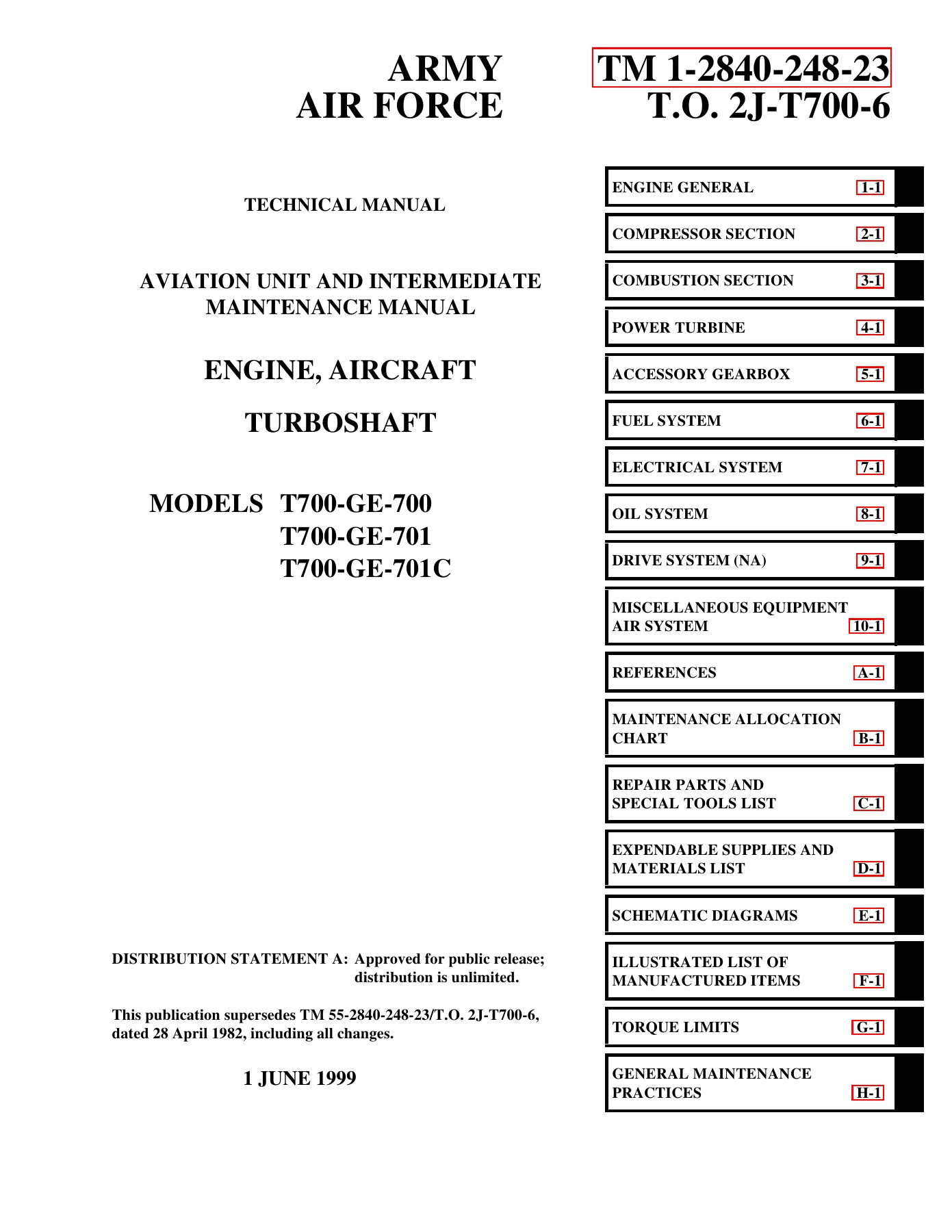
GE T700-GE-700, T700-GE-701, T700-GE-701C Turboshaft Engine Aviation Unit and Intermediate Maintenance Manual (TM 1-2840-248-23 / T.O. 2J-T700-6)
Original price was: $39.95.$24.95Current price is: $24.95.
Comprehensive 1,486-page official military Aviation Unit Maintenance (AVUM) and Aviation Intermediate Maintenance (AVIM) manual for GE T700-GE-700, T700-GE-701, and T700-GE-701C turboshaft engines powering UH-60 Black Hawk and AH-64 Apache helicopters. Features full modular teardown, 91 symptom troubleshooting trees, wiring schematics, inspection criteria, and technical specifications.
Description
Comprehensive Technical Coverage for GE T700 Turboshaft Engines
The GE T700-GE-700, T700-GE-701, T700-GE-701C Turboshaft Engine Aviation Unit and Intermediate Maintenance Manual (TM 1-2840-248-23 / T.O. 2J-T700-6) is the definitive technical authority for field-level maintenance, inspection, fault isolation, and repair of General Electric T700 series turboshaft engines. Jointly issued by Headquarters, Departments of the Army and the Air Force, this 1,486-page technical manual incorporates all changes through Change 5. It provides end-to-end guidance for maintaining front-driven turboshaft powerplants installed on front-line military helicopters, including the Sikorsky UH-60A Black Hawk, UH-60L Black Hawk, and Boeing AH-64A Apache.
File Details
- Manual Type: Aviation Unit Maintenance (AVUM) and Aviation Intermediate Maintenance (AVIM) Manual
- Engine Models Covered: General Electric T700-GE-700, T700-GE-701, and T700-GE-701C
- Document Numbers: TM 1-2840-248-23 / Technical Order T.O. 2J-T700-6 (Supersedes TM 55-2840-248-23 / T.O. 2J-T700-6 dated 28 April 1982)
- Publication Date: 1 June 1999, with Change 5 incorporated (dated 31 October 2002)
- Total Page Count: 1,486 pages
- Language: English
- File Format: Portable Document Format (PDF)
- Distribution Authorization: Distribution Statement A — Approved for public release; distribution is unlimited
Modular Maintenance Concept & Architecture
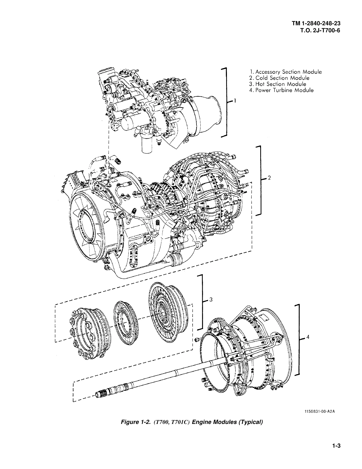
The GE T700 engine architecture is engineered around a modular maintenance concept that permits rapid field disassembly into four self-contained modules without requiring special tools at AVUM or AVIM levels. The GE T700-GE-700, T700-GE-701, T700-GE-701C Turboshaft Engine Aviation Unit and Intermediate Maintenance Manual delivers granular disassembly, inspection, cleaning, repair, and assembly procedures across each module:
- Cold Section Module: Encompasses the forward swirl frame with swirl vanes and anti-icing passages, the inlet particle separator (IPS) designed to centrifuge sand and dust into the scroll case via an accessory-gearbox-driven blower, the front frame housing the A-sump and No. 1 and No. 2 main bearings, the main frame featuring an integral 7-quart oil tank and forward engine mounts, and the compressor assembly. The compressor incorporates five axial stages with variable inlet guide vanes and variable stages 1 and 2 stator vanes, combined with a single-stage centrifugal impeller featuring backswept vanes. The module concludes with the matched diffuser and midframe casing assembly housing the B-sump, P3 air pressure taps, and service lines.
- Hot Section Module: Features a one-piece welded annular combustion liner equipped with 12 atomizing fuel injectors and film-cooling slots, a 12-segment air-cooled Stage 1 turbine nozzle assembly, a two-stage air-cooled gas generator turbine rotor assembly with bolt-retained forward and aft cooling plates, and the gas generator stator with Stage 2 turbine nozzle segments. Critical Flight Safety Critical Aircraft Parts (FSCAP) life-limit tolerances and crack criteria for Stage 1 and Stage 2 turbine disks are strictly delineated.
- Power Turbine Module: Includes the turbine case housing Stage 3 nozzle segments and thermocouple harness, the two-stage power turbine rotor assembly (Stage 3 and Stage 4 turbine disks), the exhaust frame supporting the C-sump housing and No. 5 and No. 6 bearings, and the power turbine drive shaft assembly with its internal torque reference sensor tube. Pulses generated across reference and shaft teeth are read by the Np speed and torque sensors to provide instantaneous torque, speed, and overspeed monitoring.
- Accessory Section Module: Comprises a top-mounted accessory drive gearbox driven via a radial drive shaft and power takeoff bevel gear from the compressor rotor. Internal oil and fuel coring minimizes external tubing. Mounted Line Replaceable Units (LRUs) detailed in this manual include the hydromechanical control unit (HMU), fuel boost pump, fuel filter assembly with impending bypass indicator button, tube-in-shell oil cooler, oil and scavenge pump with six individually labeled scavenge screens, electrical chip detector, alternator stator, and particle separator blower.
Engine Systems Breakdown: Fuel, Electrical, Lubrication & Air
The TM 1-2840-248-23 / T.O. 2J-T700-6 provides exhaustive system schematics and component descriptions essential for maintaining operational flight readiness:
- Fuel Control System: Contrasts the T700-GE-700 arrangement—employing two primer nozzles, a Pressurizing and Overspeed Unit (POU), and main fuel manifold—against the advanced T700-GE-701 and T700-GE-701C configurations utilizing an Overspeed and Drain Valve (ODV) and 12-nozzle main manifold. Explains the operation of the HMU high-pressure pump, Load Demand Spindle (LDS) linked to collective pitch, Power Available Spindle (PAS) linked to the cockpit power control lever, and lockout overrides.
- Electrical & Governing Systems: Complete wiring runs, connector pinouts (E1, E3, J1, J2, J3, S39), and schematic schematics for the solid-state Electrical Control Unit (ECU) on T700/T701 engines and the Digital Electronic Control (DEC) on T701C models. Details Np governing (governed to within ±1%), Turbine Gas Temperature (TGT) limiting (±5°C accuracy), twin-engine torque load-sharing, 2.5-minute contingency power logic (triggering when opposite engine torque drops to 180 ft-lb or less), Hot Start Prevention (HSP) cutting fuel when TGT exceeds 900°C (1,652°F), and DEC torque indicator fault code validation (codes 15% through 125%). Also details tracking procedures for the electromechanical History Recorder (T700/T701) and History Counter (T701C), recording LCF-1 stress cycles, LCF-2 thermal cycles, time-temperature index, and engine operating hours.
- Lubrication System: Features a self-contained dry-sump system with a 7-element gerotor oil and scavenge pump, six scavenge screens, cold-oil relief valve, oil cooler bypass relief valve, impending bypass oil filter sensor, and magnetic electrical chip detector. Includes full operational analysis of the emergency oil mist lubrication system in the A-sump and B-sump, which utilizes Stage 4 compressor bleed air to aspirate oil from dedicated internal reservoirs to sustain bearing life during partial or total loss of oil pressure.
- Pneumatic & Anti-Icing Air System: Covers Stage 5 compressor bleed air feeding both Eaton and AlliedSignal configurations of the anti-icing bleed and start valve (AI/SBV), directing hot air through hollow inlet guide vanes and swirl vanes, supplemented by hot scavenge oil circulating through scroll vanes. Explains Stage 4 bleed air distribution for labyrinth seal pressurization and power turbine thrust balancing in the C-sump, along with centerventing through hollow rotating shafts.
Diagnostic Logic Trees & Comprehensive Troubleshooting
Section VI of Chapter 1 delivers an extensive 91-procedure troubleshooting index structured in rigorous logic-diagram format. Technicians can rapidly isolate root causes for operational anomalies including engine flameout during ground or flight operations, PCL movement flameouts, starting hangs, compressor stalls above and below ground idle, high starting TGT, lack of Np governing, uncommanded deceleration, torque splits greater than 5%, chip detector illumination, fuel filter bypass warnings, low oil pressure, and overspeed test tripping failures. Standardized multimeter resistance tables and test connections via switch boxes at connector S39 allow electrical diagnostics without indiscriminate LRU replacement.
Inspection Intervals & FSCAP Life-Limited Parts Management
This technical manual specifies requirements for 10-hour / 14-day preventive maintenance checks and services (PMCS), 250-flight-hour HMU P3 fitting inspections, and comprehensive 500-flight-hour periodic inspections. In addition, it details critical Flight Safety Critical Aircraft Parts (FSCAP) requirements and service life-hour retirement intervals across Tables 1-10, 1-11, and 1-11.1 for compressor blisks, impellers, forward and aft turbine shafts, power turbine shafts, Stage 1 and 2 turbine disks, and forward and aft cooling plates, complete with mathematical formulas to reconstruct missing history recorder counts on DA Form 2408-16-1.
Chapters Covered
- Chapter 1 — Engine General: Section I General Information; Section II Equipment Description and Data; Section III Repair Parts, Special Tools, TMDE, and Support Equipment; Section IV Service Upon Receipt (Shipping Container 8145CON004-1, Hoisting, Depreservation); Section V Preventive Maintenance Checks and Services (10-Hr/14-Day, 250-Hr, 500-Hr Periodic Inspections); Section VI Troubleshooting (Engine Installed in Aircraft, 91 Logic Procedures); Section VII General Maintenance Procedures; Section VIII Engine Test in Mobile or Fixed Facilities
- Chapter 2 — Compressor Section: Cold Section Module Disassembly, Inspection, Cleaning, Repair, and Assembly (Swirl Frame, Inlet Particle Separator, Front Frame, A-Sump, Compressor Rotor Blisks, Stator Vanes, Diffuser Casing)
- Chapter 3 — Combustion Section: Hot Section Module Maintenance (Combustion Liner, Stage 1 Nozzle Assembly, Stages 1 and 2 Gas Generator Turbine Rotor, Cooling Plates, Stator Assembly, Disk Inspection)
- Chapter 4 — Power Turbine: Power Turbine Module Maintenance (Turbine Case, Power Turbine Rotor Assembly, Disks 3 & 4, Exhaust Frame, C-Sump Housing, Bearings 5 & 6, Drive Shaft and Torque Sensor Tube)
- Chapter 5 — Accessory Gearbox: Accessory Section Module Maintenance (Gearbox Housing, Radial Drive Shaft, Blower, Internal Fuel and Oil Coring, Gear Trains, Seal Replacement)
- Chapter 6 — Fuel System: Line Replaceable Units, Fuel Boost Pump, Hydromechanical Control Unit (HMU), Pressurizing and Overspeed Unit (POU), Overspeed and Drain Valve (ODV), Main Fuel Manifold, Injectors, Primer Nozzles, Fuel Filter Assembly, Pressure Sensors
- Chapter 7 — Electrical System: Electrical Control Unit (ECU), Digital Electronic Control (DEC), History Recorder, History Counter, Alternator Stator and Rotor, Thermocouple Harness, Ignition Exciter, Igniter Plugs, Speed and Torque Sensors, Color-Coded Harnesses (Yellow, Blue, Green)
- Chapter 8 — Oil System: Oil Tank, Oil Cooler Heat Exchanger, Seven-Element Gerotor Oil and Scavenge Pump, Scavenge Screens, Filter Assembly, Cold-Oil Relief Valve, Bypass Sensors, Electrical Chip Detector, Emergency Mist Lubrication
- Chapter 9 — Drive System: (Not Applicable)
- Chapter 10 — Miscellaneous Equipment / Air System: Anti-Icing Bleed and Start Valve (Eaton and AlliedSignal Configurations), Air Piping, Stage 4 and Stage 5 Bleed Air Systems, Sump Pressurization, Centerventing Lines
- Appendix A — References: Applicable Military Manuals, Technical Bulletins, and Standard Operating Procedures
- Appendix B — Maintenance Allocation Chart (MAC): Authorized Maintenance Levels (AVUM / AVIM / Depot) for Every Engine Subsystem and Tool Requirements
- Appendix C — Repair Parts and Special Tools List (RPSTL): Reference Guidance to Applicable RPSTL Publications (TM 55-2840-248-23P, TM 55-2840-238-23P, TM 55-2840-258-23P)
- Appendix D — Expendable Supplies and Materials List: Authorized Solvents, Lubricants, Sealants, Desiccants, and Consumables
- Appendix E — Schematic Diagrams: Complete Engineering Foldout Schematics for Electrical, Fuel, Lubrication, Air, and Functional Interconnects
- Appendix F — Illustrated List of Manufactured Items: Fabrication Dimensions and Specifications for Shop-Made Maintenance Tools and Test Leads
- Appendix G — Torque Limits: Comprehensive Torque Reference Tables for Standard and Flight-Safety-Critical Fasteners across all Modules
- Appendix H — General Maintenance Practices: Safety Guidelines, Lockwiring Techniques, Cable Harness Handling, Seal Installation, and Cleaning Protocols
- Glossary & Index: Definitive Technical Terms, Acronyms, Cross-Reference Nomenclature, and Comprehensive Alphabetical Subject Index
Together, these chapters and technical appendices equip aviation technicians, flight line mechanics, and intermediate depot personnel with exact military-standard procedures, factory-authorized clearances, torque values, and diagnostic steps required to maintain maximum engine performance, fuel efficiency, and flight safety across the entire T700 turboshaft family.
Professional Capability, Technical Integrity & Instant PDF Delivery
Working on sophisticated turboshaft engines requires uncompromising adherence to verified engineering data. Utilizing generic or third-party summaries risks catastrophic component failure, uncontained rotor bursts, inflight flameouts, or premature part retirement. The GE T700-GE-700, T700-GE-701, T700-GE-701C Turboshaft Engine Aviation Unit and Intermediate Maintenance Manual (TM 1-2840-248-23 / T.O. 2J-T700-6) delivers the complete, unabridged military publication, ensuring every torque specification, wiring pinout, clearance check, and borescope inspection limit is followed exactly as mandated by the U.S. Army and Air Force.
Upon purchase, this manual is delivered instantly via digital download. There are no shipping delays, backorders, or damaged physical books. The PDF file is fully unlocked, searchable, and compatible with any modern device, including Windows and Mac desktop workstations, laptops, iPads, tablets, and mobile smartphones. Technicians can easily navigate chapters via the built-in PDF bookmarks or print individual work packages, schematics, and torque tables for hands-on shop use without risking an entire paper volume. Secure your digital copy today to maintain your T700 turboshaft engine with complete technical authority.
Reviews
There are no reviews yet.