
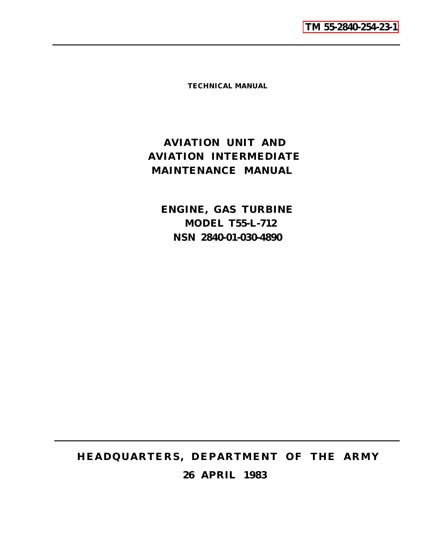

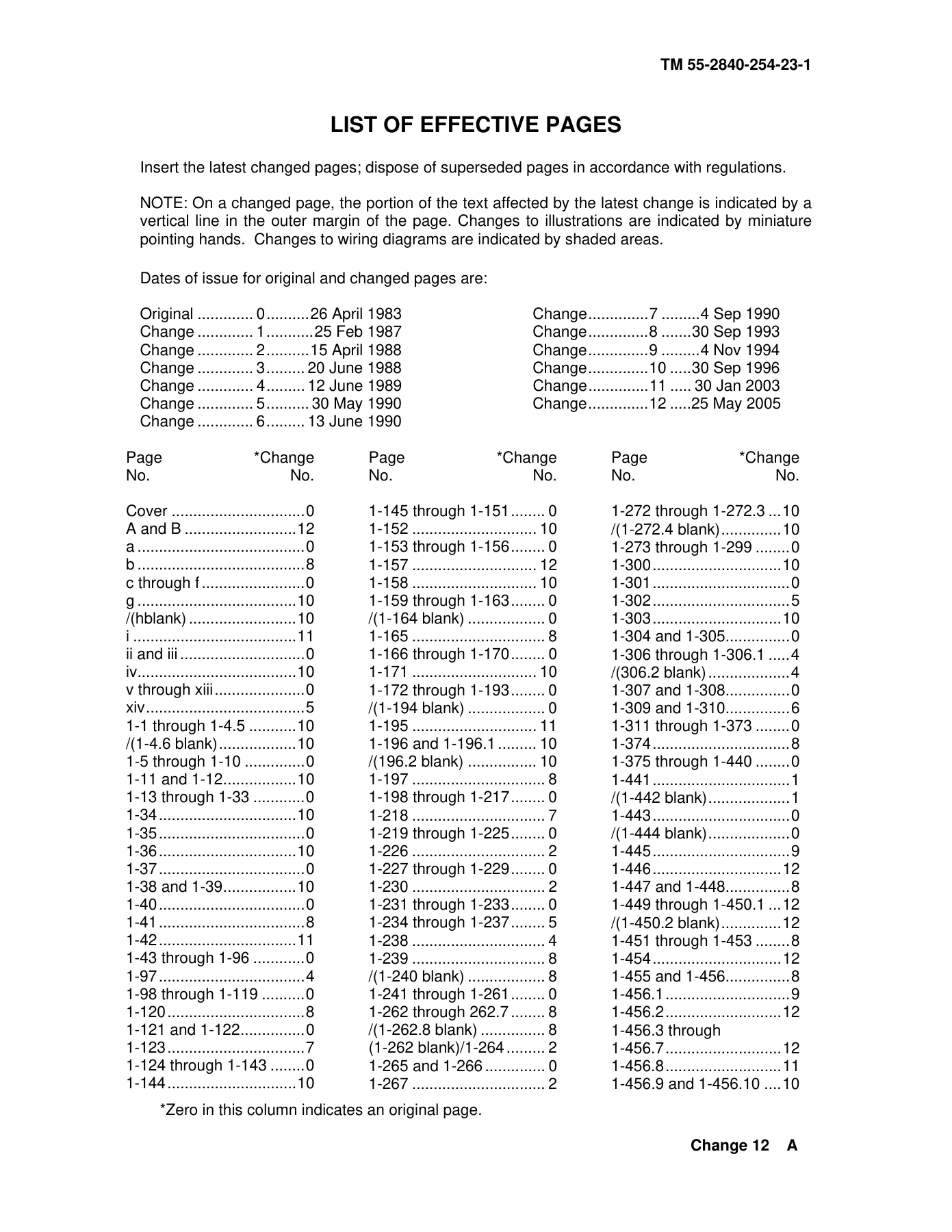
Allied Signal T55-L-712 Gas Turbine Engine Aviation Unit and Intermediate Maintenance Manual TM 55-2840-254-23-1
Original price was: $39.95.$24.95Current price is: $24.95.
Official Aviation Unit and Aviation Intermediate Maintenance Manual (AVUM and AVIM) for the Allied Signal / Textron Lycoming T55-L-712 turboshaft gas turbine engine (NSN 2840-01-030-4890), the dedicated powerplant of the Boeing CH-47 Chinook helicopter. Covers general information, system descriptions, principles of operation, diagnostic logic trees, servicing, special inspections, and maintenance procedures across 775 comprehensive pages.
Description
The Allied Signal T55-L-712 Gas Turbine Engine Aviation Unit and Intermediate Maintenance Manual TM 55-2840-254-23-1 is the definitive technical authority for field-level, unit-level, and intermediate maintenance personnel servicing the T55-L-712 turboshaft engine. Installed as the primary turboshaft powerplant for the Boeing CH-47 Chinook helicopter fleet, the T55-L-712 gas turbine engine delivers up to 3,750 shaft horsepower through a sophisticated two-stage free power turbine design. This technical manual provides complete instructions, operational principles, diagnostic troubleshooting logic trees, servicing guidelines, special inspections, and shop-level maintenance practices required to keep the engine operating safely at peak military specification standards.
File Details
- Document Title: Technical Manual Aviation Unit and Aviation Intermediate Maintenance Manual for Engine, Gas Turbine, Model T55-L-712
- Document Number: TM 55-2840-254-23-1
- National Stock Number (NSN): 2840-01-030-4890
- Equipment Model: T55-L-712 Gas Turbine Turboshaft Engine
- Manufacturer / Developer: Allied Signal / Textron Lycoming
- Primary Application: Boeing CH-47 Chinook Helicopter Series
- Publication Date: 26 April 1983 (Incorporating Changes through Change 12, 25 May 2005)
- Language: English
- Page Count: 775 Pages
- File Format: Adobe PDF (Digital Download)
Comprehensive Technical Architecture and Systems Overview
This technical manual details the full structural and mechanical envelope of the Allied Signal T55-L-712 gas turbine engine, which utilizes a reverse annular flow architecture designed for compact length, reduced airframe footprint, and maximum thermal efficiency. Within this configuration, ambient air enters through the cast magnesium-thorium air inlet housing assembly at the front of the engine, travels through a 7-stage axial-flow compressor and single-stage centrifugal impeller (delivering an overall 8:1 pressure ratio), passes through the diffuser and straightening vanes, and enters the external annular reverse-flow combustion chamber. Fuel is introduced via 28 main fuel spray nozzles (arranged in two 14-nozzle manifold halves) and two starting fuel nozzles, ignited initially by four high-energy spark igniters. Expanding combustion gases turn a two-stage gas producer turbine (N1) that directly powers the compressor rotor, before passing into a mechanically independent two-stage free power turbine (N2) whose integral shaft runs concentrically through the center of the compressor shaft to drive the forward-mounted helicopter output shaft at 100% turbine speed.
Every major sub-assembly is documented with precision mechanical illustrations, dimensional profiles, torque specifications, and system integration data in the Allied Signal T55-L-712 Gas Turbine Engine Aviation Unit and Intermediate Maintenance Manual TM 55-2840-254-23-1. Technicians gain thorough coverage of the accessory gearbox assembly mounted at the 6-o’clock position, the starter drive assembly at the 12-o’clock position, the hydromechanical fuel control system, pneumatic interstage air-bleed actuator and compressor bleed band, fuel-to-oil heat exchanger (oil cooler), dual magnetic chip detector packages, torquemeter system, and the complete engine electrical harness network.
IMAGES PREVIEW
Chapters Covered
- Chapter 1: Introduction and Engine General
- Section I: General Information (Scope, Maintenance Forms, Destruction of Materiel, Nomenclature Cross-Reference, EIR Reporting, Flight Safety Critical Aircraft Parts / FSCAP Program List)
- Section II: Equipment Description and Data (Characteristics, Capabilities, Directional References, Clock Positions, Equipment Operating Data, Safety Precautions for Magnesium-Thorium Castings)
- Section III: Principles of Operation (Reverse Annular Gas Turbine Flow Path, Compressor Section, Combustor Section, Gas Producer Turbine, Free Power Turbine, Accessory Gear Section Drive Trains, Fuel Distribution System, Electrical and Ignition System, Lubrication and Scavenge System, Torquemeter Operation)
- Section IV: Repair Parts, Special Tools, TMDE, and Support Equipment (Table 1-1 Tool Reference Codes T1 through T67)
- Section V: Service Upon Receipt (Tasks 1-25 through 1-29: Inspection of Pressurized Shipping and Storage Container, Depressurization and De-canning, Engine Depreservation and Activation, Installation and Removal from Maintenance Stand)
- Section VI: Hoisting (Tasks 1-30 and 1-31: Installation and Removal of Aircraft Maintenance Sling T60)
- Section VII: Troubleshooting (Tasks 1-32 through 1-73.1: Master Symptom Index and Detailed Step-by-Step Logic Tree Flowcharts)
- Section VIII: Servicing (Tasks 1-74 through 1-77: Engine Oil Servicing, Oil Draining, Conversion between MIL-L-7808 and MIL-L-23699 Lubricating Oils)
- Section IX: Preventive Maintenance Checks and Services (Tasks 1-78 through 1-93: Special Inspections for N1/N2 Overspeed, Coastdown Time Verification, Excessive G-Loads, Dropped Engine Evaluation, Power Turbine Overtorque, Contaminated Fuel and Oil Diagnostics, AOAP Serviceability Verification, Chip Detector Contamination Classification, Bearing Seal Leakage Testing, Static Oil Leakage Inspection, Compressor Stall/Surge, Foreign Object Ingestion / FOD Repair Limits, Hot End Inspection)
- Section X: Maintenance Procedures (Tasks 1-94 through 1-110: Component Servicing, Strainer and Filter Replacements, Bleed Band Adjustments, Fuel Control Priming, Ground Idle Adjustments)
- Section XI: Preparation for Storage and Shipment (Tasks 1-111 through 1-113: Engine Preservation, Container Preparation, Packaging into Pressurized Reusable Steel Container)
- Section XII: Standard Torque Limits (General Fastener Torque Specifications)
- Section XIII: Standard Practices and Procedures (Safety Wire Installation, Electrical Bonding, Cleaning, and General Aviation Practices)
- Subject Index and Appendices Reference Overview: Complete alphabetical cross-reference index mapping every symptom, maintenance task, inspection protocol, and assembly operation to exact task numbers.
Rather than providing generalized summaries, this technical manual supplies aircraft powerplant repairers (MOS 68B) and quality control inspectors with explicit, authorized procedures. Every single task begins with a standardized Initial Setup framework identifying the exact maintenance category (AVUM or AVIM), required tool kits, specialized support fixtures, expendable materials (E-codes), mandatory replacement parts, required personnel, safety hazards, and prerequisite equipment configurations before any mechanical work begins.
Flight Safety Critical Aircraft Parts (FSCAP) Compliance
Flight safety is paramount on the T55-L-712 turboshaft engine. Chapter 1 establishes mandatory compliance requirements for the Flight Safety Critical Aircraft Parts (FSCAP) program. Because non-conforming critical characteristics can cause cataclysmic in-flight failure, the manual catalogs every FSCAP component by part number and nomenclature—including compressor rotor blades, axial compressor disks, centrifugal impellers, gas producer turbine discs, power turbine rotors, turbine nozzles, high-stress spur and bevel gearshafts, tie bolts, and critical annular ball and roller bearings. Maintenance technicians are instructed on special handling protocols, non-destructive inspection mandates, and the strict limits of field-level repairability versus mandatory depot-level replacement.
Diagnostic Troubleshooting Logic Trees
A primary strength of the Allied Signal T55-L-712 Gas Turbine Engine Aviation Unit and Intermediate Maintenance Manual TM 55-2840-254-23-1 is its exhaustive 40-scenario troubleshooting chapter. Utilizing clear logic tree flowcharts backed by component locator illustrations, technicians can isolate faults systematically without guesswork. Troubleshooting trees cover every operational discrepancy, including:
- Starting and Ignition Anomalies: Starter failing to crank or low cranking speed, failure to ignite with zero snapping sounds, normal ignition with no combustion, fuel control priming failure, torching starts, and solenoid valve electrical faults.
- Engine Speed and Governing Control: Failure to attain ground idle speed, incorrect ground idle rpm, low torque or high torque at maximum N1 power lever setting, N1 transient overshooting without reaching N2 governing speed, N2 overspeed and underspeed oscillations, and hunting or erratic speeds while governing on power turbine governors.
- Airflow and Compressor Instability: Interstage bleed band popping or compressor surge during throttle advance, failure of compressor bleed band to close, and interstage pneumatic actuator calibration discrepancies.
- Exhaust and Gas Temperature Spikes: High Power Turbine Inlet Temperature (PTIT) during steady-state cruise, excessive PTIT during ground starts, temperature overshoots during rapid acceleration transients, and thermocouple harness continuity isolation.
- Lubrication and Oil System Discrepancies: High or low lubricating oil pressure, oil pressure needle fluctuations exceeding 10 psi, high oil operating temperature, static oil leakage draining into the combustion chamber or bleed band, oil consumption exceeding two quarts per hour, and low oil level switch diagnostics.
- Mechanical Integrity Checks: Sub-25-second abnormal coastdown time, engine binding, rubbing sounds during manual rotor rotation, and severe mechanical vibration evaluation.
Special Inspections, Contamination Analysis, and Bearing Seal Leakage Checks
Beyond routine servicing, this manual provides detailed instructions for mission-critical special inspections triggered by operational incidents. Technicians receive explicit protocols for evaluating engines subjected to N1 or N2 overspeeds, excessive flight G-loads, rough handling or dropped engine incidents, and power turbine overtorque events. The manual provides precise damage criteria for Foreign Object Damage (FOD), allowing field dressing of minor nicks and dents on first-stage axial compressor rotor blades using hand files without removing the compressor housing, provided blade tip clearance remains above the mandatory 0.019-inch threshold.
For the lubrication system, the manual incorporates advanced contamination inspection procedures following Army Oil Analysis Program (AOAP) laboratory recommendations or cockpit chip light illumination. It details the precise categorization of metal debris: Category A (single chip larger than 0.120 x 0.120 inch), Category B (chips larger than 0.025 inch), and Category C (fine fuzz or particles smaller than 0.025 inch), accompanied by strict criteria governing when an engine can be cleared for flight versus when intermediate teardown or depot retirement is mandatory. Furthermore, dedicated AVIM procedures guide technicians through vacuum decay checks of the No. 2, No. 4, and No. 5 bearing package carbon seals using the specialized T44 Seal Leakage Tester to confirm seal integrity before returning powerplants to active flight lines.
Professional Capability and Instant PDF Delivery
The Allied Signal T55-L-712 Gas Turbine Engine Aviation Unit and Intermediate Maintenance Manual TM 55-2840-254-23-1 gives aircraft mechanics, aviation maintenance technicians, restoration shops, and military turbine specialists the exact technical framework required to perform reliable, professional-grade powerplant care. Operating, servicing, and overhauling high-output turboshaft engines requires strict adherence to military-grade torque limits, detailed test-cell run-up procedures, and authorized disassembly/assembly sequences. Relying on aftermarket approximations risks severe component destruction, compressor stall, or hot-section thermal failure. Available as an instant digital PDF download, this manual delivers immediate access on laptops, tablets, or desktop workstations in the hangar or shop, with fully printable pages and ultra-clear schematics ready for immediate deployment on the engine stand.
Reviews
There are no reviews yet.