★ TRUSTED BY 321,897+ PROFESSIONALS WORLDWIDE
🏢
Trusted Business
Verified & Licensed
🛡️
Virus Free Files
100% Safe Downloads
🔒
Secure Payment
SSL Protected
Instant Delivery
Available Immediately
Sale!

Genie S-100 S-105 S-120 S-125 Boom Lift Service Manual – Part No. 62401 Rev A4

Original price was: $39.95.Current price is: $22.95.

Genuine Genie S-100, S-105, S-120 and S-125 boom lift Service Manual (Part No. 62401, Rev A4) covering scheduled maintenance, fault code troubleshooting, electrical and hydraulic schematics, and full repair procedures. Instant PDF download.

Instant PDF Download
Available immediately
💾
Save to Your Device
Download & keep forever
🛡️
Antivirus Scanned
100% virus-free
🌍
Trusted Worldwide
175,000+ customers

Description

Genie S-100 S-105 S-120 S-125 Service Manual – Part No. 62401 Rev A4

This Genie S-100 S-105 S-120 S-125 Service Manual is the factory-style reference for keeping these telescopic boom lifts running safely and reliably. Covering the S-100 and S-105 (serial numbers 101 to 136) and the S-120 and S-125 (serial numbers 101 to 403), the manual walks a technician through scheduled maintenance, fault code diagnosis, electrical and hydraulic schematics, and step-by-step repair procedures for every major system on the machine.

File Details

  • Manual type: Service Manual (Part No. 62401, Rev A4, January 2010)
  • Covers: Genie S-100, Genie S-105, Genie S-120 and Genie S-125 boom lifts
  • Serial number ranges: S-100 & S-105 101 to 136; S-120 & S-125 101 to 403
  • Language: English
  • Page count: 497 pages
  • File format: PDF, instant download

IMAGES PREVIEW

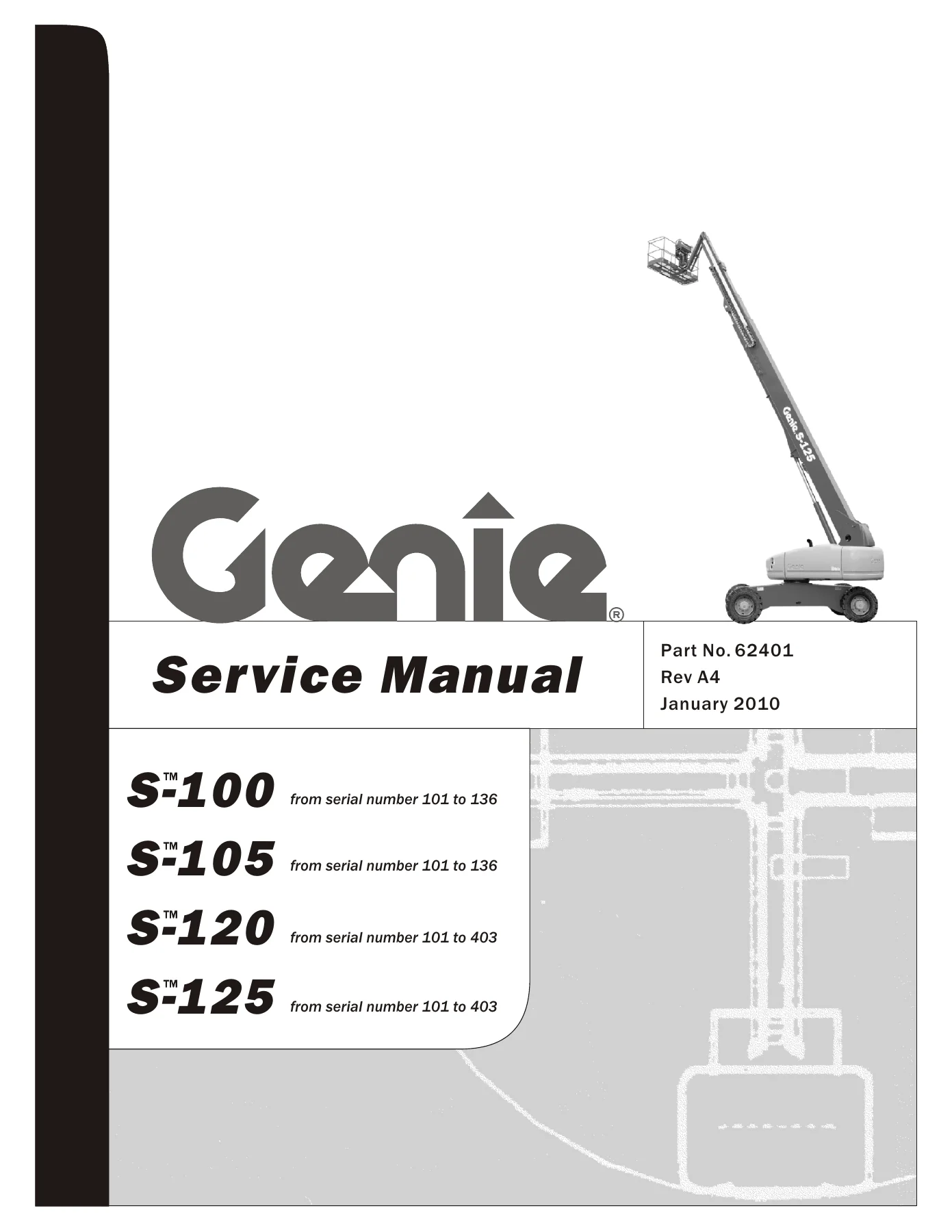
Genie S-100 S-105 S-120 S-125 Boom Lift Service Manual - Part No. 62401 Rev A4 — PDF page 1 preview
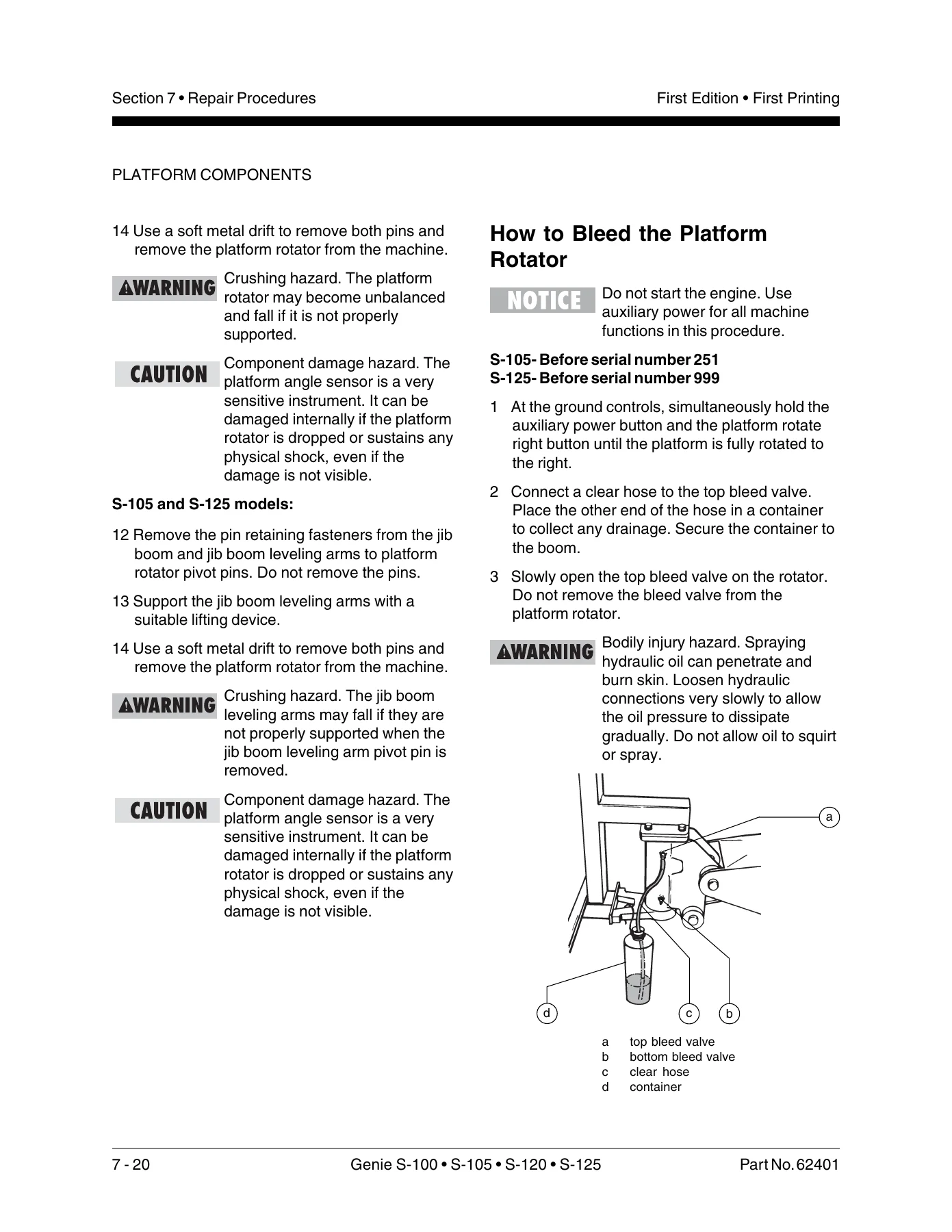
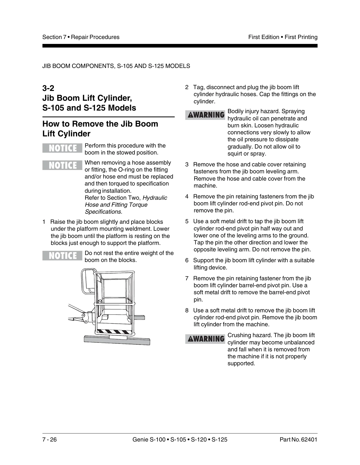
Genie S-100 S-105 S-120 S-125 Boom Lift Service Manual - Part No. 62401 Rev A4 — PDF page 372 preview
Genie S-100 S-105 S-120 S-125 Boom Lift Service Manual - Part No. 62401 Rev A4 — PDF page 378 preview

Chapters Covered

  • Section One – Safety Rules
  • Section Two – Specifications (machine, performance, hydraulic, and Perkins 1004-42 / Cummins B3.9L / Deutz F4L 913 engine specifications)
  • Section Three – Theory of Operation
  • Section Four – Scheduled Maintenance Procedures (A through E service intervals, engine maintenance by engine type, hydraulic filters, drive hub oil, turntable bearing lubrication)
  • Section Five – Troubleshooting Flow Charts (fault code chart plus 44 individual flow charts covering engine, drive, boom, platform, jib, steering and axle faults)
  • Section Six – Schematics (electrical component list, wire circuit legend, relay layout, controller pin legends, limit switch harness schematics, safety circuit schematic, and hydraulic schematics for every model and steer configuration)
  • Section Seven – Repair Procedures (platform controls and components, jib boom, boom components including lift and extension cylinders, turntable covers, engine components, ground controls, limit switches, hydraulic pumps and manifolds, fuel and hydraulic tanks, turntable rotation, and axle components)
  • Appendix – Electrical Schematic, Genie part number 62304 (Drive Chassis and Platform Control, Ground Controls)

Together these sections give a technician everything needed to take a Genie S-100, S-105, S-120 or S-125 from a fault code on the display module through to a diagnosed and repaired machine, without guessing at torque values, pressures, or wiring.

Why Technicians Rely on This Manual

The Genie S-100 S-105 S-120 S-125 Service Manual is built around the actual maintenance inspection report Genie dealers use, so the A, B, C, D and E service intervals in Section Four line up exactly with what the machine’s own service history should show. The 44 troubleshooting flow charts in Section Five take a symptom – such as boom up inoperative, drive enable fault, or platform level down inoperative – and lead through the checks and expected values needed to isolate the cause, rather than leaving the technician to reverse-engineer the electrical schematic on their own.

Complete PDF Bookmark Tree

Complete Bookmarks

The complete bookmarks in the “Genie S-100 S-105 S-120 S-125 Boom Lift Service Manual – Part No. 62401 Rev A4” are as follows:

Coverp. 1
Safety Rulesp. 5
Table of Contentsp. 7
Specificationsp. 19
Machine Specifications S-120/125p. 19
Performance Specifications S-120/125p. 20
Machine Specifications S-100/105p. 21
Performance Specifications S-100/105p. 23
Hydraulic Specificationsp. 24
Perkins Engine 1004-42p. 25
Cummins Engine B3.9Lp. 26
Deutz Engine F4L 913p. 27
Hydraulic Hose and Fitting Torque Specificationsp. 28
Theory of Operationp. 29
Scheduled Maintenance Proceduresp. 33
Table A Procedurep. 39
A-1p. 39
A-2 to A-3p. 40
A-4 to A-5p. 41
A-6 to A-7p. 42
A-8 to A-9p. 44
A-10p. 45
A-11 to A-12p. 46
A-13 to A-14p. 47
A-15p. 48
A-16p. 49
Table B Proceduresp. 50
B-1p. 50
B-2p. 51
B-3 to B-4p. 53
B-5p. 54
B-6 to B-7p. 55
B-8p. 56
B-9 to B-10p. 57
B-11p. 58
B-12p. 59
B-13p. 62
B-14p. 63
B-15p. 64
B-16p. 65
B-17p. 71
B-18p. 72
B-19 to B-20p. 73
B-21p. 74
B-22 to B-23p. 75
Table C Proceduresp. 77
C-1 to C-2p. 77
C-3 to C-4p. 78
C-5 to C-6p. 79
Table D Proceduresp. 82
D-1p. 82
D-2p. 83
D-3p. 84
D-4p. 85
D-5p. 86
D-6p. 88
D-7 to D-8p. 90
D-9p. 91
D-10 to D-11p. 92
D-12p. 93
Table E Proceduresp. 95
E-1p. 95
E-2 to E-3p. 97
E-4 to E-5p. 98
E-6 to E-7p. 99
E-8 to E-9p. 100
E-10 to E-11p. 101
E-12 to E-13p. 102
Troubleshooting Flow Chartsp. 103
Fault Code Chartp. 105
Chart 1p. 113
Chart 2p. 118
Chart 3p. 124
Chart 4p. 127
Chart 5p. 130
Chart 6p. 132
Chart 7p. 133
Chart 8p. 134
Chart 9p. 135
Chart 10p. 140
Chart 11p. 142
Chart 12p. 144
Chart 13p. 147
Chart 14p. 151
Chart 15p. 156
Chart 16p. 160
Chart 17p. 169
Chart 18p. 174
Chart 19p. 179
Chart 20p. 188
Chart 21p. 206
Chart 22p. 230
Chart 23p. 235
Chart 24p. 240
Chart 25p. 242
Chart 26p. 246
Chart 27p. 250
Chart 28p. 253
Chart 29p. 256
Chart 30p. 259
Chart 31p. 262
Chart 32p. 265
Chart 33p. 270
Chart 34p. 276
Chart 35p. 280
Chart 36p. 283
Chart 37p. 286
Chart 38p. 289
Chart 39p. 292
Chart 40p. 298
Chart 41p. 304
Chart 42p. 306
Chart 43p. 312
Chart 44p. 315
Schematicsp. 317
Electrical Componentsp. 318
Wire Circuit Legendp. 320
Wire Coloringp. 322
Limit Switchesp. 324
Relay Layoutp. 326
Platform Controller Pin Legendp. 328
Electrical Schematic Legend – Drive Chassis and Platform Controlsp. 330
Electrical Schematic Legend – Ground Controlsp. 331
Electrical Symbols Legendp. 332
Limit Switch Harness Schematicp. 333
S-100/105p. 333
S-120/125p. 334
Safety Circuit Schematicp. 335
Electrical Schematicsp. 336
Generatorsp. 336
Deutz Modelsp. 337
Cummins and Perkins Modelsp. 338
Hydraulic Symbols Legendp. 340
Hydraulic Schematicsp. 341
S-100 Models with 2 Wheel Steerp. 341
S-100 Models with 4 Wheel Steerp. 343
S-105 Models with 2 Wheel Steerp. 345
S-105 Models with 4 Wheel Steerp. 347
S-120 Modelsp. 349
S-125 Modelsp. 351
Repair Proceduresp. 353
Display Modulep. 354
Platform Controlsp. 356
1-1p. 357
1-2p. 358
1-3p. 359
1-4p. 366
1-5p. 367
Platform Componentsp. 368
2-1 to 2-2p. 368
2-3p. 370
2-4p. 373
Jib Boom Componentsp. 376
3-1p. 376
3-2p. 378
Boom Componentsp. 380
4-1p. 381
4-2p. 384
4-3p. 395
4-4p. 397
4-5p. 401
Turntable Coversp. 405
5-1p. 405
Enginesp. 407
6-1 to 6-2p. 407
6-3p. 409
6-4p. 409
Ground Controlsp. 410
7-1p. 410
7-2p. 411
7-3p. 412
Limit Switchesp. 414
8-1p. 415
Hydraulic Pumpsp. 422
9-1p. 422
9-2p. 423
9-3p. 426
9-4p. 427
Manifoldsp. 428
10-1p. 428
10-2p. 432
10-3p. 433
10-4p. 434
10-5p. 438
10-6p. 439
10-7p. 440
10-8p. 442
10-9p. 444
10-10p. 446
10-11 to 10-12p. 448
10-13p. 449
10-14p. 450
10-15p. 454
10-16p. 458
10-17p. 460
10-18p. 464
10-19p. 464
Fuel and Hydraulic Tanksp. 467
11-1p. 467
11-2p. 468
Turntable Rotation Componentsp. 470
12-1p. 470
Axle Componentsp. 474
13-1p. 474
13-2p. 476
13-3p. 478
13-4p. 479
13-5p. 480
13-6p. 481
Softwarep. 485
Diagnostic Codesp. 486
Display Modulep. 489
Electrical System Legendp. 491
Wire Circuit Legendp. 492
Web GPIp. 494
Electrical Schematic- Drive Chassis and Platform Controlsp. 495
Electrical Schematic- Ground Controlsp. 496

Because the S-100 and S-105 share a chassis with the larger S-120 and S-125, but differ in platform height, load capacity, and jib boom fitment, this manual keeps the model-specific specifications, hydraulic schematics, and drive speeds clearly separated throughout, so there’s no confusion about which torque value or pressure setting applies to which machine.

Get the Most from Your Genie S-100 S-105 S-120 S-125

With this Genie S-100 S-105 S-120 S-125 Service Manual, a shop or independent technician can perform correct scheduled maintenance, chase down fault codes with the manufacturer’s own flow charts, and carry out repairs on the platform, boom, turntable, hydraulic system, and engine using the exact procedures, torque values, and pressure settings Genie built the machine to. Getting these figures wrong on a boom lift isn’t a minor inconvenience – it affects the safety envelope, the drive brakes, and the structural cables that keep an operator safe at height, so working from the correct reference matters.

This is an instant PDF download – there’s no shipping wait and no physical book to store. Once purchased, the file downloads straight to any computer, tablet or phone, and can be printed in full or by section for shop use.
Reviews

There are no reviews yet.

Be the first to review “Genie S-100 S-105 S-120 S-125 Boom Lift Service Manual – Part No. 62401 Rev A4”

What Our Customers Say

★★★★★ Live reviews from customers
Loading customer reviews...
0
    0
    Your Cart
    Your cart is emptyReturn to Shop
    🛒
    Recently Purchased
    🕒 verified order