
Geoclima TB6 T12 Universal Chiller Control Technical Specifications Manual – SP925GEO Rev 52
Original price was: $39.95.$24.95Current price is: $24.95.
740-page technical specifications manual for the Geoclima Universal Chiller Control TB6 and T12 boards. Covers hardware architecture, I/O channels, step/stepless/inverter/Turbocor actuators, compressor and circuit controls, alarm definitions, system setup, and Modbus/PEMS/SNMP monitoring. SW GEOUCH36, Rev 52.
Description
Geoclima TB6 T12 Universal Chiller Control Technical Specifications Manual
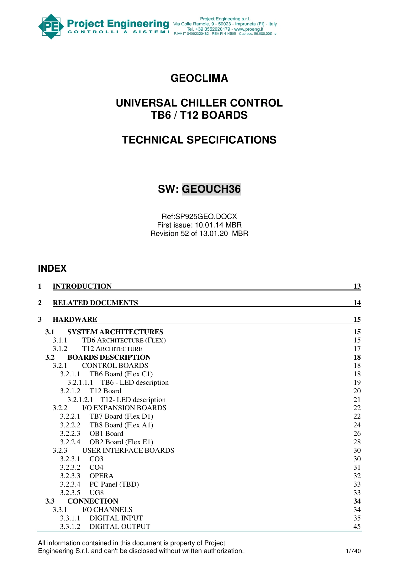
This is the complete 740-page technical specifications document for the Geoclima Universal Chiller Control system built around the TB6 and T12 main boards. Reference SP925GEO, Revision 52 of 13.01.20, covering software version GEOUCH36. It documents the control architecture, the full I/O channel set, the actuator logic for step, stepless, inverter and Turbocor compressors, circuit-level controls, alarm definitions, user interface screens, and system setup parameters. The manual covers chiller configurations from a single compressor up to eight compressors, with or without parallel arrangement, on one or two refrigerating circuits, and includes the associated expansion boards (TB7, TB8, OB1, OB2) and user interfaces (CO3, CO4, OPERA7, OPERA10, UG8).
File Details
- Manual Type: Technical Specifications
- Brand: Geoclima / Project Engineering s.r.l.
- Model: Universal Chiller Control TB6 / T12 Boards
- Document Reference: SP925GEO.DOCX
- Software Version: GEOUCH36
- Revision: 52
- Revision Date: 13.01.20
- First Issue: 10.01.14
- Language: English
- Page Count: 740
- Format: PDF
Chapters Covered
The manual is organised into eleven top-level sections. The table below lists the main chapters and their principal sub-sections as printed in the document index.
- 1. Introduction — Supported chiller configurations, notes and colour-code key
- 2. Related Documents — Hardware and software specification references
- 3. Hardware
- 3.1 System Architectures — TB6 (Flex) and T12 architectures
- 3.2 Boards Description — Control boards, I/O expansion boards, user interface boards
- 3.3 Connection — I/O channels, board connections, TB6/TB7/TB8/T12/OB1/OB2 connections
- 4. Installing Sequence of Operation
- 4.1 TB6 Board configuration
- 4.2 User Interface configuration
- 4.3 TB7 Board configuration
- 4.4 TB8 Board configuration
- 4.5 T12 Board configuration
- 4.6 EEV Board configuration (OB1 and OB2)
- 4.7 Turbocor connection
- 4.8 Mounting instruction
- 5. Software
- 5.1 Operations — Configuration, machine startup, starting, shut-down, only pumps mode, external enable, emergency mode, software filter, time block scheduling
- 5.2 Machine Controls — Unit capacity control (local/remote/open loop), actuators (step, stepless, inverter, Turbocor), special capacity limitations, heating mode management, split unit, free cooling control, pumps control, evaporator controls, condenser controls, pulsed HGB solenoids, cooler heater wrapped, units lead lag, power line analyzer, unit performance evaluation, probe redundancy, warnings by digital output, auxiliary transducers, unit check, water closing valve, remote cooler, emergency mode for high TAE, unit fast restart, load bypass valve, thermostatic controls
- 5.3 Compressor Controls — Switch on/off procedures, pump down, limitations, economizer and liquid injection, suction heater, Turbocor options, current monitoring, capacity monitoring, HGB in high DP
- 5.4 Circuit Controls — Fluid solenoid, discharge pressure control, discharge temperature monitoring, EEV control, parallel compressor management, LPA control, subcooled liquid temperature, discharge insulation valve
- 5.5 Alarms — Machine alarms, compressor alarms, circuit alarms, auto reset
- 5.6 Data Displayed — Standard screens and Custom#1 screens
- 5.7 System Setup — User, Manufacturer, Service, I/O setup, alarm history, SW update, timer, time and date, interface, unit check, system info, I/O mapping
- 5.8 Multi Language Data Display — English, German, Italian, French, Russian
IMAGES PREVIEW

- 6. Monitoring Systems
- 6.1 Local Monitoring — PEMS, Ethernet, Modbus, SNMP communication
- 6.2 Remote Service System — Remote monitoring through gateway, direct error messages, SMS protocol
- 7. Programming and Software Update — Programming by PC, SD/USB, OnBoard
- 8. Testing Features — Hardware test mode, software test mode
- 9. Debugging Features — SMS protocol debug
- 10. FW Release Notes
- 11. Revision History
Across these chapters the manual gives a technician the complete electrical and logical picture of the Geoclima chiller controller. It names every digital input, digital output, analog input and analog output the controller can use, explains how each board in the system is addressed and wired, and describes the software routines that decide when compressors stage up or down, how electronic expansion valves are driven, how fans are modulated on discharge pressure, and how the controller responds to probes, alarms and external enable signals. The actuator chapters go deep into the three main compressor control families — step with head unloaders, stepless with slider solenoids or hot gas bypass, inverter-driven compressors with envelope protection, and Turbocor compressors with parallel, true parallel and hybrid sequencing. Each control is described with its timing parameters, staging tables and limitations.
Hardware and I/O Coverage
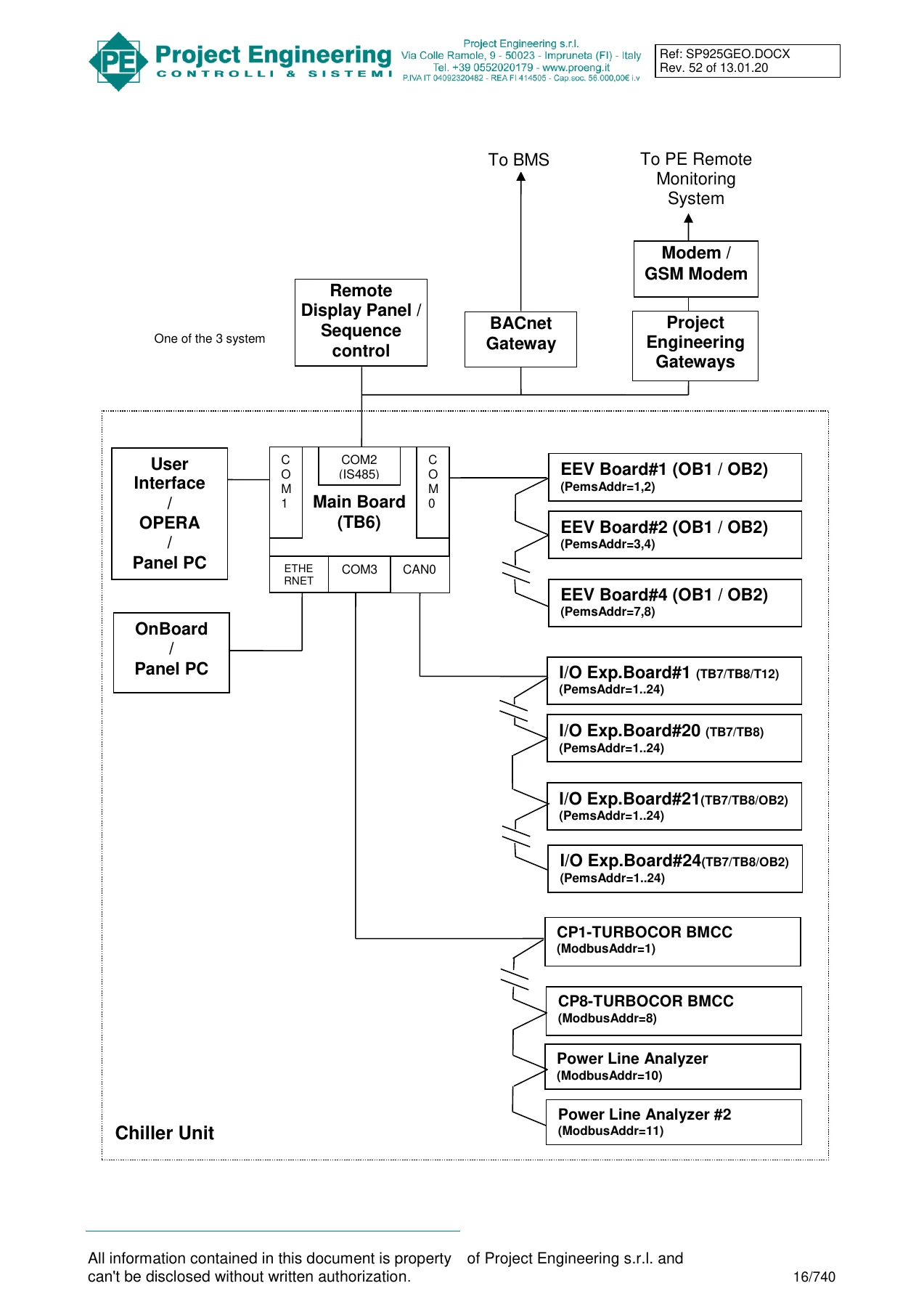
The hardware section documents the TB6 main board and the T12 main board, along with the TB7 and TB8 I/O expansion boards and the OB1/OB2 EEV driver boards. Board-level details include power supply requirements, serial port assignments (COM0–COM3), CAN bus ports, USB and microSD support, real-time clock, LED behaviour, and dip-switch addressing. The I/O channel tables list every logic channel — from evaporator pump circuit breakers and flow switches through to compressor unloaders, economizer solenoids, liquid injection ports, and the analog channels for suction and discharge pressure, water temperatures, and current transducers.
Connection diagrams and pinout tables are provided for each board, including the TB6 interconnection bus, the TB7 digital input and output pin assignments, the TB8 analog input and output channels, the T12 digital and analog I/O, and the OB1/OB2 EEV valve outputs. The manual also documents the Turboctor connection over Modbus, the Power Line Analyzer wiring, and the SD/USB programming ports.
Software and Control Logic
The software section is the largest part of the manual. It explains how the controller computes cooling or heating demand through a PID loop, how the setpoint can be fixed, switched by digital input, or read from a remote analog sensor, and how the demand is then translated into compressor staging by the selected actuator. Step control is described for one, two or three head unloaders, with staging tables that show exactly how many compressors are on and which unloader solenoids are energised at each capacity step. Stepless control is covered with its slider solenoid logic, current-feedback option, and hot gas bypass modulation. Inverter control includes the Danfoss envelope maps for VZH and VTZ compressor families, with minimum and maximum speed limits per operating area and discharge temperature protection. Turbocor control covers sequential, parallel, true parallel and hybrid modes, with the Modbus register list used to read and write compressor data.
Circuit-level controls are detailed for electronic expansion valves — the manual describes PID control based on suction superheat, discharge superheat, evaporator liquid level, condenser liquid level, and a linear relation with compressor capacity. MOP management, minimum and maximum opening limits, manual control, extra opening and extra closing for Turbocor, and second EEV valve management in heat pump mode are all documented. Discharge pressure control, fan speed optimisation, fan speed limitation by time periods and noise level, and dynamic setpoint on DP control are explained with their parameters and timing.
Free cooling is covered in its three forms: standard free cooling with valve and fan control, free cooling with dry cooler, and free cooling with liquid pumps (LPA). The LPA control logic is presented as a state machine with LPU starting cycles, fixed-on states, and EEV/fan behaviour in each state. Evaporator and condenser controls include two-barrel management, water pressure and flow rate monitoring, flooded evaporator liquid level control, oil separator thermostat, oil recovery, air cooler management, and heater control.
Alarms and Diagnostics
The alarm chapter lists every machine alarm, compressor alarm, and circuit alarm the controller can raise. Each entry describes the trigger condition, the action taken (compressor halt, pump down, system halt), and the reset logic — automatic after a delay, manual via the ESC key, or auto-reset with a count limit. Probe alarms for LWT, RWT, suction and discharge pressures and temperatures, oil pressure, current, and liquid level are all covered. Refrigerant alarms include suction pressure, discharge pressure, suction temperature, high discharge temperature, superheat limits, gas leak, and discharge insulation valve anomaly. Turbocor-specific alarms and their bitmap positions are listed, with the fault descriptions passed from the compressor.
The data display chapter describes every standard screen — main, second, third, thermostats, heat recovery, units lead lag, stepless control staging, free cooling, dry cooler, evaporator and condenser pumps, power line analyzer, evaporator and condenser screens, evaporative condenser, evap system, air coolers, chiller performance, noise performance, fast alarm history, compressor screens, envelope screens, multipurpose screens, remote cooler circuits, and alarm screens. The Custom#1 screen set is also documented for branded configurations.
System Setup and Monitoring
The system setup chapter documents the menu structure and every parameter in the User, Service, Manufacturer, and I/O setup groups. Parameter ranges, defaults and units are given for the machine parameters, temperature control, compressor control, refrigerating circuit control, discharge pressure control, EEV control, free cooling, LPA, evap system, heating, multipurpose, pumps, power control, evaporator and condenser control, remote monitoring, serial bus, and password groups. The I/O mapping section explains how logic channels are assigned to physical channels on the expansion boards, with the full parameter list for digital and analog mapping.
Monitoring systems are covered for PEMS over serial and Ethernet, Modbus RTU on COM2 or via a Modbus gateway, and SNMPv2 with trap messages. The Modbus function codes implemented are listed, and the error message format is explained. Remote service through a GSM modem or gateway is documented, including the SMS protocol for alarm notification and setup parameter reading/writing.
Programming and Testing
Programming instructions are provided for PC connection, SD card update, USB key update, and OnBoard remote update. The testing features chapter describes the hardware test mode with relay rotation, all-relay-on, input-to-output, analog input, RTC, hardware key, user test, and modem GSM test, plus the software test mode where every EEPROM parameter can be changed.
What This Manual Enables
With this document a controls engineer, commissioning technician or service engineer can configure a Geoclima TB6 or T12 chiller controller from scratch — addressing every expansion board, mapping every I/O channel, selecting the compressor control logic, setting the PID parameters, programming the EEV algorithm, defining the alarm thresholds, and setting up Modbus, PEMS or SNMP communications. It is the reference needed to understand why a compressor stages when it does, how the controller responds to a probe failure, what each alarm means, and how to change the parameters that govern the machine’s behaviour.
When a chiller is not holding setpoint, when a compressor will not load, when an EEV is hunting, when a Turbocor is tripping, or when the controller reports an alarm that is not in the operator’s experience, this manual is where the answer lies. The alarm chapter alone saves hours of guesswork by naming the exact conditions that trigger each fault and the reset path required.
The manual is delivered as an instant PDF download. No shipping, no waiting for a physical book. It can be stored on a laptop, tablet or phone, searched on screen, and printed if a paper copy is needed in the plant room. This is the full 740-page Revision 52 document, covering software GEOUCH36, as issued in January 2020.
Reviews
There are no reviews yet.