Grove Crane RT600E Operator’s Manual 088-03 – PDF DOWNLOAD
$28.95
Grove Crane RT600E Operator’s Manual 088-03 – PDF DOWNLOAD
Description
Grove Crane RT600E Operator’s Manual 088-03 – PDF DOWNLOAD
FILE DETAILS:
Grove Crane RT600E Operator’s Manual 088-03 – PDF DOWNLOAD
Language : English
Pages : 157
Downloadable : Yes
File Type : PDF
IMAGES PREVIEW OF THE MANUAL:
DESCRIPTION:
Grove Crane RT600E Operator’s Manual 088-03 – PDF DOWNLOAD
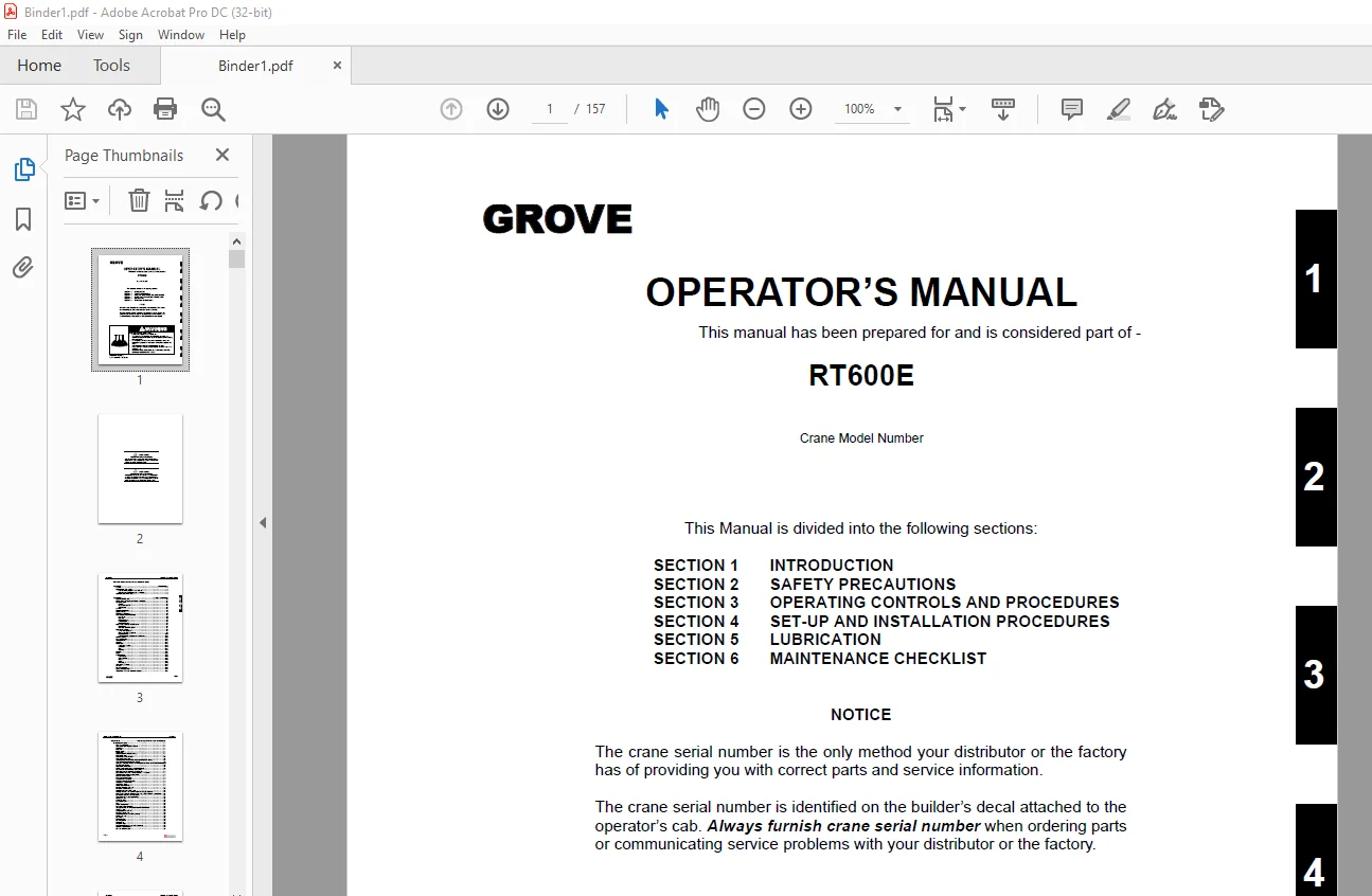
INTRODUCTION:
- This handbook has been compiled to assist you in properly operating and maintaining your Grove
Crane. - Before placing the crane in service, take time to thoroughly familiarize yourself with the contents
of this manual. After all sections have been read and understood, retain the manual for future
reference in a readily accessible location. - The Grove Crane has been designed for maximum performance with minimum maintenance. With
proper care, years of trouble-free service can be expected. - Constant improvement and engineering progress makes it necessary that we reserve the right to make
specification and equipment changes without notice. - Grove and our Dealer Network want to ensure your satisfaction with our products and
customer support. Your local dealer is the best equipped and most knowledgeable to assist you for
parts, service and warranty issues. They have the facilities, parts, factory trained personnel, and
the information to assist you in a timely manner. We request that you first contact them for
assistance. If you feel you need factory assistance, please ask the dealer’s service
management to coordinate the contact on your behalf. - Engine operating procedures and routine maintenance procedures are supplied in a separate manual
with each crane, and should be referred to for detailed information. - Information in this manual does not replace federal, state, or local regulations, safety codes, or
insurance requirements.
GENERAL:
- The rough terrain crane incorporates an all welded steel frame, using planetary drive axles to
provide four-wheel drive. Axle steering is accomplished utilizing hydraulic steer cylinders. The
engine is mounted at the rear of the crane and provides motive power through a six speed forward
and reverse transmission. Hydraulic, double box, sliding beam outriggers are integral with the
frame.
The carrier frame incorporates an integral fifth wheel, to which the rear axle is mounted, to - provide axle oscillation. Axle oscillation lockout is automatic when the superstructure rotates
from the travel position. - The superstructure is capable of 360° rotation in either direction. All crane functions are
controlled from the fully- enclosed cab mounted on the superstructure. The crane is equipped with a
four-section, cable-synchronized boom. Additional reach is obtained by utilizing an optional
swingaway boom extension. Lifting is provided by a main
hoist and an optional auxiliary hoist.
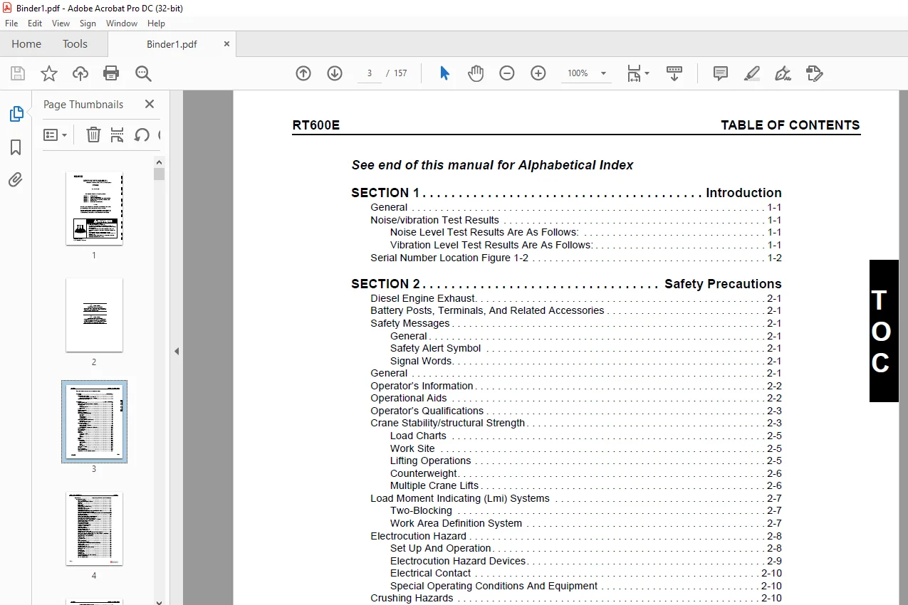
TABLE OF CONTENTS:
Grove Crane RT600E Operator’s Manual 088-03 – PDF DOWNLOAD
SECTION 1 Introduction
General 1-1
Noise/vibration Test Results 1-1
Noise Level Test Results Are As Follows: 1-1
Vibration Level Test Results Are As Follows: 1-1
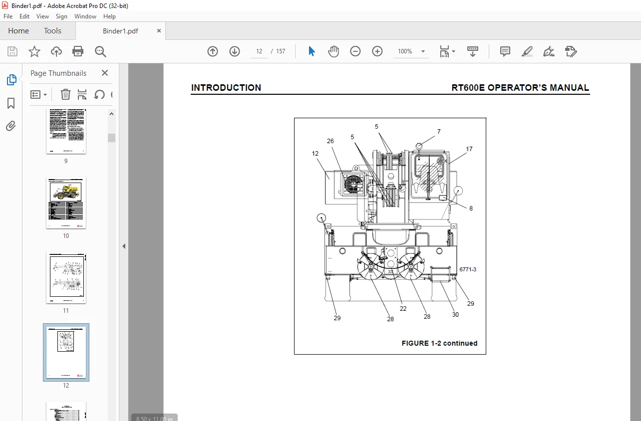
Serial Number Location Figure 1-2 1-2
SECTION 2 Safety Precautions
Diesel Engine Exhaust 2-1
Battery Posts, Terminals, And Related Accessories 2-1
Safety Messages 2-1
General 2-1
Safety Alert Symbol 2-1
Signal Words 2-1
General 2-1
Operator’s Information 2-2
Operational Aids 2-2
Operator’s Qualifications 2-3
Crane Stability/structural Strength 2-3
Load Charts 2-5
Work Site 2-5
Lifting Operations 2-5
Counterweight 2-6
Multiple Crane Lifts 2-6
Load Moment Indicating (Lmi) Systems 2-7
Two-Blocking 2-7
Work Area Definition System 2-7
Electrocution Hazard 2-8
Set Up And Operation 2-8
Electrocution Hazard Devices 2-9
Electrical Contact 2-10
Special Operating Conditions And Equipment 2-10
Crushing Hazards 2-10
Personnel Handling 2-11
Travel Operation 2-12
Accidents 2-12
Maintenance 2-12
Service And Repairs 2-13
Lubrication 2-13
Tires 2-13
Wire Rope 2-13
Batteries 2-14
Engine 2-15
Work Practices 2-15
Crane Access 2-15
Job Preparation 2-15
Working 2-15
Lifting 2-16
Hand Signals 2-16
Transporting The Crane 2-17
Shut-down 2-17
Boom Extension/jib 2-18
Cold Weather Operation 2-18
Temperature Effects On Hydraulic Cylinders 2-18
TABLE OF CONTENTS RT600E
TOC-2
SECTION 3 Operating Controls And Procedures
Controls And Indicators 3-1
Hand Throttle Control 3-1
Transmission Oil Temperature Gauge 3-1
Fuel Gauge 3-1
Voltmeter 3-1
Ignition Switch 3-1
Tachometer 3-1
Engine Coolant Temperature Gauge 3-1
Foot Throttle Pedal 3-1
Crane Function Power Switch 3-6
Transmission Shift Lever 3-6
Telescope or Auxiliary Hoist Control Lever (Single Axis Option) 3-6
Swing Control Lever (Single Axis Option) 3-6
Swing And Telescope or Swing and Auxiliary Hoist Control Lever (Dual Axis Option)3-6
Water In Fuel Indicator 3-6
Rear Steer Control Switch 3-6
Auxiliary Hoist Speed Selector Switch (Optional) 3-6
Boom Lift Control Lever (Single Axis Option) 3-7
Main Hoist Control Lever (Single Axis Option) 3-7
Boom Lift And Main Hoist Control Lever (Dual Axis Option) 3-7
Telescope Control Foot Pedal (Optional) 3-7
Hoist Rotation Indicators 3-7
Drive Axle Selector Switch 3-7
Outrigger Control Switches 3-7
Outriggers Extend/Retract Switch 3-7
Swing Brake Control Switch 3-7
Swing Brake Pedal 3-7
Service Brake Foot Pedal 3-7
Low Brake Pressure Indicator 3-7
Park Brake Control Switch 3-8
Turntable Lock Control (Pin Type) 3-8
360 Degree Swing Lock Control (Positive Lock Type) (Optional) 3-8
Load Moment Indicating (LMI) and Work Area Definition System Control Panel 3-8
Low Steer Pressure Indicator (CE Units) 3-8
Transmission Service Indicator (XMSN) 3-8
Headlights Switch 3-8
Work Light Switch 3-8
Cab Circulating Fan 3-8
Horn 3-8
Hazard Lights Switch 3-8
Boom Light Switch (Optional) 3-8
Turn Signal Lever and Windshield Wiper/Washer Controls 3-8
Cab Dome Light 3-9
Skylight Wiper (Not Shown) 3-9
Bubble Level Indicator 3-9
Air Conditioner Control Switch (Optional) 3-9
Heat Control Knob 3-9
Fan Switch 3-9
Defroster Switch 3-9
Fire Extinguisher 3-9
Defroster Fan 3-9
Windshield Wiper 3-9
Axle Differential Lock Control Switch (Optional) 3-9
Right Turn Signal Indicator 3-9
Left Turn Signal Indicator 3-9
TOC-3
RT600E TABLE OF CONTENTS
T
OC
GROVE
Rear Wheels Not Centered Indicator 3-9
Hydraulic Boost Switch 3-10
Hoist 3rd Wrap Indicator (Optional CE Units) 3-10
Main Hoist Speed Selector Switch 3-10
12 VDC Accessory Outlet 3-10
Spotlight (Optional) 3-10
Fuse Panel 3-10
Wait To Start Indicator 3-10
Engine Diagnostics Switches 3-10
Engine Stop Indicator 3-10
Engine Warning Indicator 3-10
Engine Service Indicator 3-10
Throttle Mode Switch 3-11
Electronic System Diagnostic Indicator 3-11
Work Light 3-11
-29oC Indicator (Optional) 3-11
Strobe Light or Beacon (Not Shown) 3-11
LMI Lockout (All Units) and LMI Lockout Alarm (CE Units) (Not Shown) 3-11
Buzzer (Not Shown) 3-11
Hourmeter (Not Shown) 3-11
Skylight Wiper (Not Shown) 3-11
Backup Alarm (Not Shown) 3-11
Data Link and Service Connector (Not Shown) 3-11
Anemometer (Not Shown) 3-11
Emergency Exit 3-11
Operating Procedures 3-12
New Crane Conditioning 3-12
Pre-Starting Checks 3-12
Cold Weather Operation 3-13
Engine Operation 3-13
Crane Travel Operation 3-15
Travel On Slopes 3-17
General Crane Operation 3-19
Using Your Load Chart 3-19
Crane Functions 3-21
Control Lever Lockout System 3-26
Stowing And Parking 3-26
SECTION 4 Set-up And Installation Procedures
General 4-1
Installing Cable On The Hoist 4-1
Cable Reeving 4-1
Dead-end Rigging/wedge Sockets 4-5
Installing Wedge And Socket 4-5
Erecting And Stowing The Swingaway Boom Extension 4-7
General Warnings 4-7
Erecting 4-7
Stowing 4-8
Setting The Offset 4-12
Changing Swingaway Boom Extension From Telescoping Type To Fixed Type 4-12
Setting The Telescoping Swingaway Length 4-13
SECTION 5 Lubrication
General 5-1
Lubrication Intervals 5-1
Arctic Conditions Below -18°C (0°F) 5-1
TABLE OF CONTENTS RT600E
TOC-4
Arctic Conditions Down To -40°F 5-1
Surface Protection for Cylinder Rods 5-2
Wire Rope Lubrication 5-2
lubrication points 5-3
CraneLUBE 5-3
Safety 5-3
Steering and Suspension 5-4
Axles 5-6
Drive Train 5-8
Drive Train (continued) 5-10
Turntable 5-12
Outriggers 5-14
Boom 5-16
Boom (continued) 5-18
Hoist 5-20
Hoist 5-22
Hydraulic 5-24
SECTION 6 Maintenance Checklist
General 6-1
Instructions 6-1
Daily or 10 Hour Check List 6-1
Need help? Contact: [email protected]
PLEASE NOTE:
- This is the same manual used by the DEALERSHIPS to SERVICE your vehicle.
- The manual can be all yours – Once payment is complete, you will be taken to the download page from where you can download the manual. All in 2-5 minutes time!!
- Need any other service / repair / parts manual, please feel free to contact us at heydownloadss @gmail.com . We may surprise you with a nice offer
S.V