
Grove TM9120 Crane Parts Manual – Serial 79402 (December 2006) PDF Download
Original price was: $39.95.$24.95Current price is: $24.95.
Complete Grove TM9120 parts manual for serial number 79402, dated December 22, 2006. Approximately 1,485 pages of part numbers, exploded views, and component breakdowns covering the boom, cab, hoist, turntable, engine, drive train, axles, outriggers, hydraulics, electrical systems, and more.
Description
Grove TM9120 Parts Manual – Serial 79402
This is the complete parts manual for the Grove TM9120 crane, specifically covering serial number 79402, with a publication date of December 22, 2006 (Revision 15). This comprehensive document spans approximately 1,485 pages and serves as the definitive component reference for identifying, ordering, and replacing parts on this exact machine. Whether you are rebuilding a boom section, replacing hydraulic cylinders, tracking down an obscure electrical connector, or verifying a part number before placing an order, this manual provides the exploded views, part numbers, descriptions, and quantities you need.
File Details
- Manual Type: Parts Manual / Component Index
- Brand: Grove (Manitowoc Crane Group)
- Model: TM9120
- Serial Number: 79402
- Publication Date: December 22, 2006
- Revision: 15
- Language: English
- Page Count: Approximately 1,485 pages
- File Format: PDF
Chapters Covered
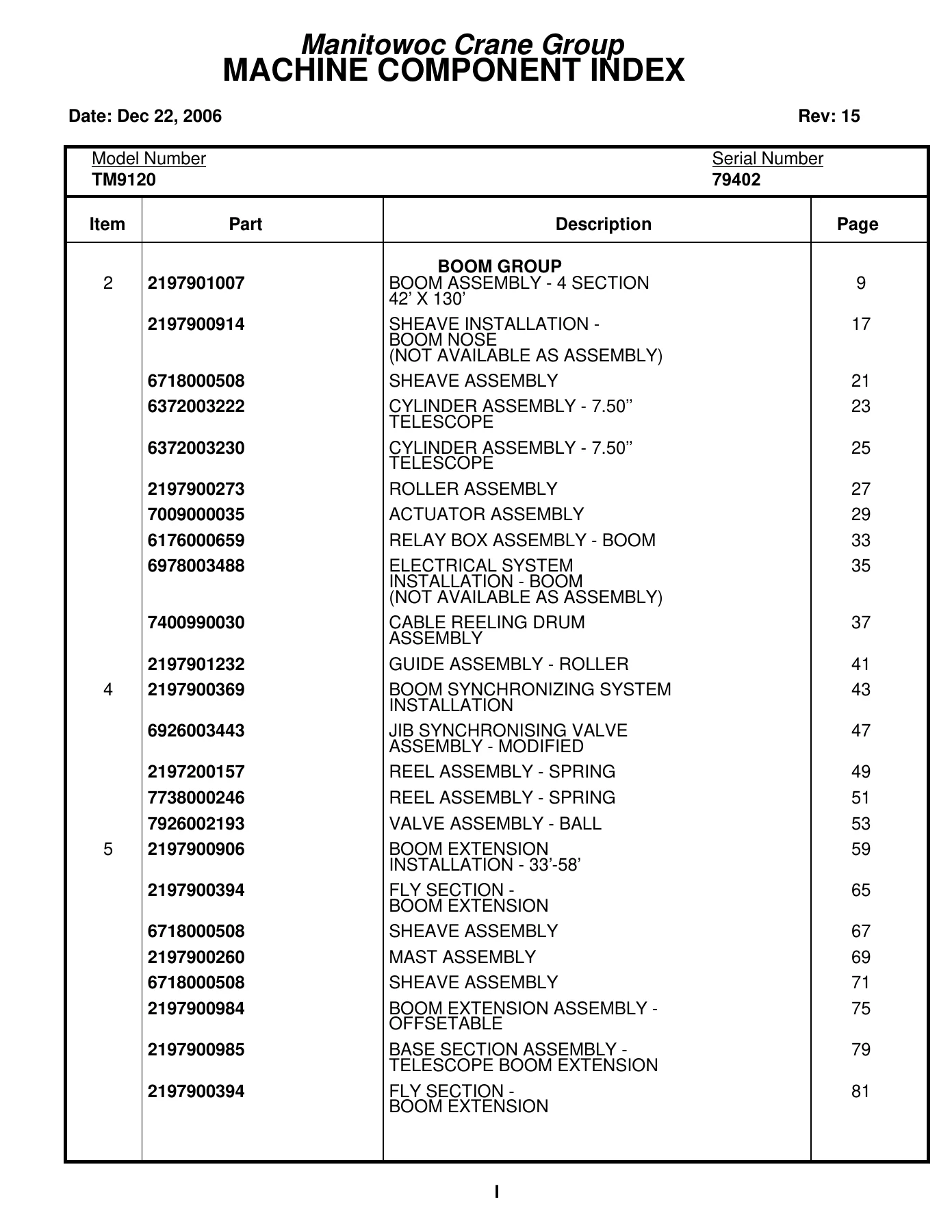
- Boom Group — Boom Assembly (4 Section 42′ x 130′), Sheave Installation, Cylinder Assemblies (7.50″), Roller Assembly, Actuator Assembly, Relay Box Assembly, Electrical System Installation, Cable Reeling Drum Assembly, Guide Assembly, Boom Synchronizing System, Jib Synchronising Valve, Reel Assemblies, Valve Assembly (Ball), Boom Extension Installations (33′-58′), Fly Section, Mast Assemblies, Boom Extension Assembly (Offsetable), Base Section Assembly (Telescope Boom Extension)
- Carrier Installation – Boom Extension
- Jib Installation – 116′
- Boom Extension Assembly – 32′
- Lights Installation – Boom
- Ball Assembly – 750# Headache
- PAT System Installation — Cable Reel Assembly (LWG2), Slipring Assembly (11 Cond.), Console Assembly (DS350GW), Central Unit Assembly, Pressure Transducer MTG, 33′-58′ Tele-Offset Swingaway, Anti 2 Block Weight Assembly, Minimum Layer Device, Decal Installation, Wiring Diagrams
- Cab Group — Electrical System Installation (S/S), Harness Assembly, Box Assembly (CWT Removal Switch), Control Assembly, Cable Assembly (Counterweight Switch), Cab Installation, Window Assembly, Accelerator Pedal Assembly, Valve Assembly (Brake), Console Installation, Harness Installations, Control Pedal and Valve Installation, Valve Assembly (Control), Acoustical Installation, Light Installation (Flasher), Light Assembly (Strobe), Control Seat Installation, Seat Assemblies, Controller Assembly (Single Axis), Harness Assembly (Seat Switches), Windshield Washer Installation, Wiper and Washer Installation (Skylight), Fan Installation (Cab Circulating), Fan Assembly (12 Volt), Extinguisher Installation (Fire), Mat Installation (Floor), Heater and Defroster Installation
- Control Handles Installation
- Control Valve Group — Control Valve Installation (Main Hoist), Valve Assembly (3 Section), Valve Assembly (Pressure Reducing), Valve Bank Assembly, Valve Assembly (Integrated Control), Valve Assembly (3 Station Solenoid), Valve Assembly (2 Section), Valve Assembly (Solenoid), Valve Assembly (Shuttle), Hydraulic Lines Installations (Counterweight Removal, Pressure Check Panel, Swing, Swing and Swing Brake, Main and Auxiliary Hoist, Main Hoist, Telescope, Telescope & Aux Hoist, Lift, Supply/Pressure/Return, Outrigger), Valve Assembly (Relief)
- Hoist Group — Hoist Installation (Main), Hoist Assembly (HO50 – 26G), Hoist Drive Kit (HO50), Motor Assembly, Valve Assembly (Control), Support Assembly (Drum), Cable Follower Installation, Roller Assembly, Rotation Indicator Installation, Rotation Indicator Assembly
- Turntable Group — Turntable Drive Installation, Drive Assembly (Swing), Reducer Assembly (Gear), Motor Assembly, Lock Assembly (Swing), Cylinder Installation (Lift), Cylinder Assembly (Lift), Pin Installation (Boom Pivot Shaft/Upper Lift Cyl)
- Fuel Tank Installation
- Sheet Metal Installation (Left Side)
- Swivel Installation – Electric/Hydraulic — Swivel Assembly (3 Port), Ring Assembly (Slip), Electric & Hyd Swivel Assembly
- Counterweight Installation – Removable — Counterweight Assembly (Upper and Lower), Cylinder Assembly (3 1/2″ Counterweight), Bearing Bolt Installation, Lock Pin Installation (Turntable), Lock Installation (Positive Swing), Lever Installation (Positive Swing Lock)
- Reel Installation – Hose — Brake Assembly (Hose Reel), Valve Assembly (Solenoid 3 Way 2 Position), Motor Assembly
- Cooler Installation – Oil — Cooler Assembly (Oil), Motor Assembly (Oil Cooler), Fan Assembly (Oil Cooler)
- Hydraulic Reservoir Installation — Hydraulic Reservoir Assembly, Filter Assembly, Cover Assembly (16 1/4″ Inspection)
- Hydraulic Lines Installation – Lift
- Engine Group — Engine Installation (Cummins 6CTA8.3), Drive Assembly (Pump), Pump Assembly (3 Section), Clutch Installation, Clutch Assembly, Electrical Systems Installation (Engine), Harness Assembly (Engine), Radiator Installation, Exhaust and Air Cleaner Installation, Cleaner Assembly (Air), Quick Start Installation, Battery Installation, Harness Assembly (Alternator/Battery), Hood Installation (Engine), Door Assembly (Access), Weatherstrip Installation, Grill Installation
- Drive Train Group — Drive Line Installation, Drive Line Assemblies, Auxiliary Transmission Installation, Auxiliary Transmission Assembly, Transmission Assemblies, Transmission Shift Installation, Transmission Master Control Assembly, Clutch Control Rod Installation
- Axle Group — Axle and Steering Installation (Front), Axle Assembly (Front), Cylinder Assembly (2 1/2″ Steer), Chamber Assembly (Brake), Arm Assembly (Torque), Torque Arm Assembly, Steering Gear Assembly, Universal Joint Assembly, Link Assembly (Drag), Vertical Socket Drag Link Assembly, Axle Installation (Rear), Loose Hardware Kit, Drive Line Assembly, Axle Assemblies, Brake Chamber Assembly, Air Brake Disconnect Installation, Valve Extension Installation, Tire and Wheel Assembly, Hydraulic Lines Installation (Spring Suspension), Regulator Assembly (Flow), Valve Assembly (Relief)
- Outrigger Group — Outrigger Box Installation (Front), Cylinder Assembly (6.00″ Outrigger Jack), Cylinder Assembly (Extension), Cylinder Assembly (4″ Outrigger Power Pin), Valve Assembly (4 Stack Outrigger Solenoid), Cable Assembly (Outrigger Box), Valve Assembly (Solenoid), Harness Assembly (Ground), Harness Assembly (Rear Outrigger Box), Box Installation (Outrigger – Rear), Rear Outrigger Box Assembly, Cylinder Assembly (5″ Jack), Control Box and Pin Installation, Remote Pin Control Assemblies, Stabilizer Installation (Front Center), Float Storage Installation (Outrigger), Float Assembly (Outrigger)
- Frame Group — Frame Assembly (Carrier), Fenders and Decking Installation, Sling Box Installation, Box Assembly (Sling), Box Assembly (Front Outrigger), Beam Assembly (Outrigger), Cam Assembly, Cable Assembly (Outrigger Box), Tank Installation (Fuel), Fuel Tank Assembly, Battery Installation, Rest Installation (Boom), Hookblock Tie-Down Installation, Counterweight Support Installation (Upper), Sling Assembly, Exterior Lights and Horn Installation, Light Assemblies (Turnsignal and Marker), Lights Assembly (Identification), Light Assembly (License Plate), Alarm Installation (Back-Up), Tire Inflation Kit Installation, Air Lines Installation, Air Tank and Valve Installation, Dryer Assembly (Air), Valve Assemblies (Spring Brake, Quick Release, Supply Dump), Air Lines Installation (Carrier), Valve Assembly (Check), Electrical System Installation (Carrier), Harness Assembly (Carrier Frame), Harness Assembly (Swivel), Reservoir Installation (Hydraulic), Valve Installation (Carrier Hydraulic), Valve Assemblies, Hydraulic Lines Installation (Supply/Pressure/Return), Valve Assembly (Relief), Valve Assembly (Residual Check), Decal Installation
- Cab Carrier Group — Cab Installation, Washer Installation (Windshield), Seat Assembly, Column Assembly, Valve Assembly (Dual Brake), Control Assembly (Throttle – Electric), Switch Assembly, Shaft Assembly (U-Joint), Console Installation (Front), Harness Installations, Harness Assemblies (Front Console, Cab), Air Lines Installation (Console), Extinguisher Installation (Fire), Rear View Mirror Installation, Head and Loop Assembly (Mirror), Acoustical Installation, Electrical System Installation (Carrier Cab), Harness Assembly (Carrier Cab), Panel Assembly (Fuse and Connector), Harness Assembly (Fuse Panel), Fan Installation (Cab Circulating), Fan Assembly (12 Volt), Floor Mat Installation
- Engine Carrier Group — Engine Installation (Cummins N14-460E), Link Assembly (Control), Transmission Assembly, Controller Assembly (Slave Unit), Pump Assembly (Steer), Radiator Installation, Air Cleaner and Muffler Installation, Cleaner Assembly (Air), Cover Installation (Exhaust), Quick Start Installation, Hood Installation (Engine), Weatherstrip Installation (Engine Hood)
- Alphabetical Index
- Numerical Index
- Recommended Spare Parts List
- Belt and Filter Maintenance List
- Foot Note Index
What This Parts Manual Provides
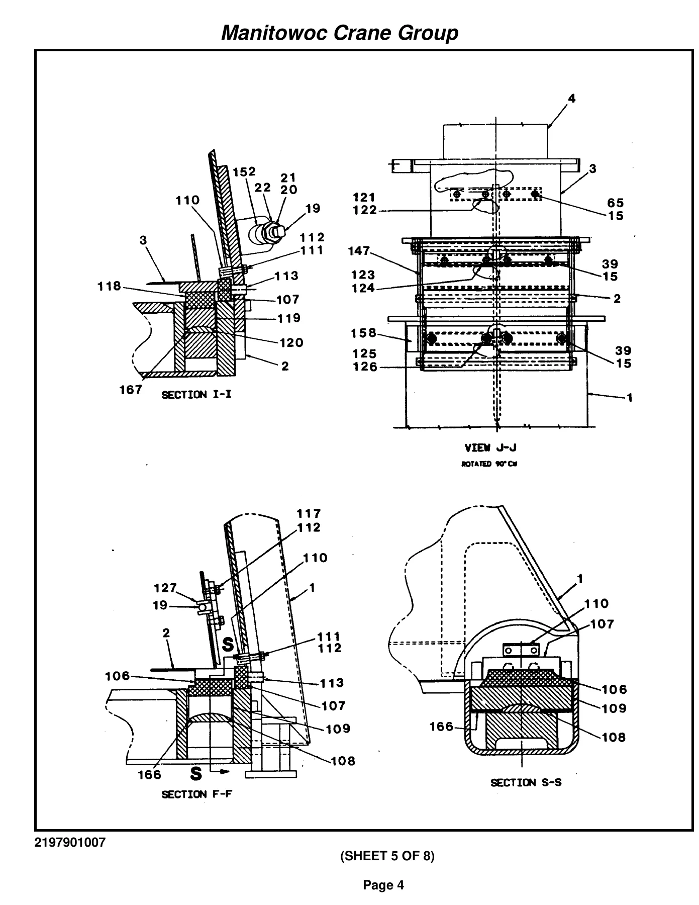
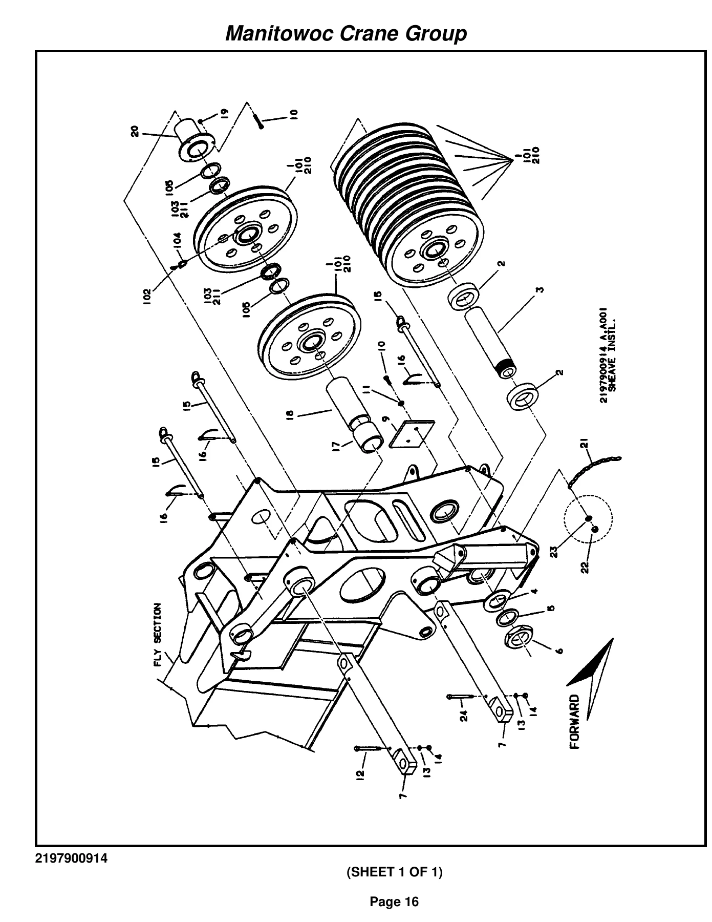
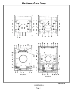
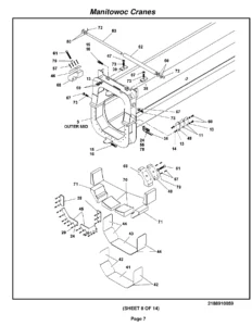
This Grove TM9120 parts manual is not a generic overview — it is a serial-number-specific component reference built for the exact machine carrying serial number 79402. Every section is organized to help you locate the precise part you need for your crane. The document opens with a machine component index that maps every major assembly, part number, and description to the page where its detailed breakdown begins. From there, each system is presented with exploded illustrations, cross-sectional diagrams, and complete parts lists showing item numbers, Grove part numbers, quantities, and descriptions.
For the boom alone, the manual covers the four-section 42′ x 130′ boom assembly, sheave installations for the boom nose, telescope cylinders, roller assemblies, cable reeling drums, synchronizing systems, jib installations, and multiple boom extension configurations including the 32′ and 33′-58′ offsetable assemblies. The hoist section details the HO50 main hoist with complete drive kit breakdowns, motor assemblies, control valves, drum supports, and cable follower components. The turntable group includes the swing drive assembly, gear reducer, swing lock, and lift cylinder installation with pivot pin details.
The engine group covers the Cummins 6CTA8.3 installation in exhaustive detail — pump drive assembly, three-section pump, clutch assembly, electrical systems, radiator, exhaust, air cleaner, battery, and hood components. For machines equipped with the Cummins N14-460E, there is a dedicated engine carrier group with its own transmission assembly, slave controller, steering pump, and related installation parts. The drive train section breaks down the drive lines, auxiliary transmission, and clutch control rod installation. The axle group covers both front and rear axles with steering cylinders, brake chambers, torque arms, steering gear, drag links, and the complete rear axle installation including spring suspension hydraulic lines.
The outrigger group is particularly comprehensive, covering front and rear outrigger box installations, jack cylinders (6.00″ and 5″), extension cylinders, power pin cylinders (4″), four-stack and five-stack solenoid valve assemblies, remote pin control boxes, stabilizer installation, and float storage assemblies. The frame group ties everything together with carrier frame assembly, fenders and decking, sling box, fuel tank installation, battery installation, boom rest, hookblock tie-down, counterweight support, exterior lighting, air systems, and the complete carrier hydraulic system with reservoir, valves, and line installations.
Beyond the major systems, the manual includes the PAT system installation (LMI) with cable reel assembly, slipring, console, central unit, pressure transducer mounting, anti-two-block weight assembly, minimum layer device, and decal installation. The cab group covers everything from the cab structure, windows, accelerator pedal, brake valve, console, seat assemblies, controller assemblies, windshield washer, wiper, fan, fire extinguisher, floor mat, and heater/defroster. The cab carrier group duplicates and extends this coverage for the carrier cab with its own fuse panel, harness assemblies, and air lines. Electrical system installations are broken down by location — boom, engine, cab, carrier, carrier cab — with harness assemblies, connectors, terminals, and receptacle details.
The manual also includes alphabetical and numerical indexes that let you search by part number or description to find the exact page where a component is called out. A recommended spare parts list identifies critical wear items with recommended stocking quantities for 1-year, 2-year, and 3-year intervals. A belt and filter maintenance list provides the part numbers for scheduled maintenance items. The foot note index explains the symbols and notes used throughout the parts lists.
Who This Manual Is For
This Grove TM9120 parts manual is an essential resource for anyone responsible for maintaining, repairing, or rebuilding the crane with serial number 79402. Equipment owners, fleet managers, maintenance supervisors, mechanics, and parts personnel will all find this manual indispensable for accurate parts identification and ordering. Because it is serial-number-specific, it eliminates the guesswork that comes with generic parts catalogs — you can be confident that the part numbers and assembly configurations shown match your machine.
The exploded views and cross-sectional diagrams are particularly valuable for understanding how components fit together, which is critical when disassembling a system for repair or when verifying that you have all the necessary parts before starting a job. The parts lists provide quantities, so you know exactly how many of each fastener, seal, bearing, or fitting you need. The recommended spare parts list helps you stock the most commonly needed items so you can minimize downtime.
Why This Manual Matters
Using the correct part numbers and following the proper assembly sequences is essential for safe and reliable crane operation. A wrong part can lead to premature failure, damage to adjacent components, or unsafe operating conditions. This manual gives you the information you need to get it right the first time. It eliminates the back-and-forth of trying to identify a part from a description alone, and it reduces the risk of ordering incorrect components that must be returned or, worse, installed and then fail.
The detailed illustrations and cross-references also help you understand how systems interact. For example, the hydraulic lines installation sections show not just the hoses and tubes but also the fittings, adapters, O-rings, and clamps that connect them. The electrical sections show connectors, terminals, plugs, and harness assemblies. This level of detail is what makes a factory parts manual so much more valuable than a generic aftermarket catalog.
Get Your Grove TM9120 Parts Manual Today
IMAGES PREVIEW
This Grove TM9120 parts manual for serial number 79402 is available as an instant PDF download. There is no shipping, no waiting for a physical book to arrive, and no risk of a damaged or incomplete paper copy. The PDF can be viewed on any device — computer, tablet, or smartphone — and you can print the pages you need for use in the shop. Whether you are performing routine maintenance, planning a major rebuild, or simply want to have the correct parts information on hand, this manual delivers the complete component reference for your crane. Order now and have the full manual in your hands in minutes.

Reviews
There are no reviews yet.