
GSK980TDc Turning CNC Programming Operation Installation Connection User Manual – Efamatic Edition PDF
Original price was: $39.95.$24.95Current price is: $24.95.
GSK980TDc Turning CNC Programming Operation Installation Connection User Manual in PDF, covering programming, operation, installation, connection, parameters, diagnostics and machining examples for GSK980TDc and GSK980TDc-V systems.
Description
File Details
- Manual type: Programming, Operation, Installation and Connection User Manual
- Brand: GSK CNC Equipment Co., Ltd.
- Model: GSK980TDc and GSK980TDc-V
- Language: English
- Page count: 470
- File format: PDF
- Edition: Efamatic Edition
Chapters Covered
- I Programming: Chapter 1 Programming – GSK980TDc introduction, technical specification, environment and conditions, power supply, guard, CNC system of machine tools and CNC machine tools, programming fundamentals, coordinates definition, machine coordinate system and machine zero, workpiece coordinate system and program zero, interpolation function, absolute and incremental programming, diameter and radius programming, structure of an NC program, main program and subprogram, program run, basic axis incremental system, additional axis incremental system
- Chapter 2 MSTF Command – M miscellaneous function, end of program M02, end of program run M30, subprogram call M98, return from subprogram M99, macro program call M9000 to M9999, standard PLC M commands, program stop M00, optional stop M01, spindle CW CCW and stop M03 M04 M05, cooling M08 M09, tailstock M10 M11, chuck M12 M13, spindle position and speed control M14 M15, spindle clamped and released M20 M21, second spindle position and speed switch M24 M25, lubricating M32 M33, spindle automatic gear change M41 to M44, spindle 8-point orientation M50 to M58, second spindle M63 M64 M65, spindle function, spindle speed switching value control, spindle speed analog voltage control, constant surface speed control G96, constant rotational speed control G97, spindle override, multiple spindle control, Cs contour control, tool function, tool control, tool life management
- Chapter 3 G Commands – command groups, modal and non-modal commands, omitting words, rapid traverse G00, linear interpolation G01, circular interpolation G02 G03, three-point circular interpolation G05, ellipse interpolation G6.2 G6.3, parabola interpolation G7.2 G7.3, plane selection G17 to G19, polar coordinate interpolation G12.1 G13.1, cylindrical interpolation G7.1, chamfering function, dwell G04, machine zero function, G28, G30, skip interpolation G31, automatic tool offset G36 G37, workpiece coordinate system G50, local coordinate system, workpiece coordinate system G54 to G59, fixed cycle commands G90 G94, multiple cycle commands G71 G72 G73 G70 G74 G75, thread cutting commands G32 G32.1 G34 G33 G84 G88 G92 G76, constant surface speed control G96, constant rotational speed control G97, feedrate per minute G98, feedrate per rev G99, additional axis function, macro commands, statement macro command, metric and inch switch
- Chapter 4 Tool Nose Radius Compensation G41 G42 – application, imaginary tool nose direction, compensation value setting, command format, compensation direction, notes, application, tool nose radius compensation offset path, inner and outer side, tool traversing when starting tool, tool traversing in offset mode, offset canceling mode, tool interference check, commands for canceling compensation vector temporarily
- II Operation – panel division, state indication, edit keypad, menu display, machine panel, operation mode summary, display interface, POS interface, PRG interface, TOOL OFFSET interface, ALARM interface, SETTING interface, PARAMETER interfaces, diagnosis interface, graph interface, ladder interface, power on and off, protection, overtravel protection, emergency operation, manual operation, coordinate axis move, manual feed, manual rapid traverse, speed tune, other manual operations, spindle control, spindle jog, cooling, lubricating, chuck, tailstock, hydraulic control, manual tool change, spindle override, MPG and STEP operation, step feed, MPG feed, MDI operation, block input, block execution, parameter setting, data alteration, program edit and management, program creation, searching, inserting, deleting, altering, copying and pasting, program save, macro program edit, deleting programs, selecting a program, executing a program, renaming a program, copying a program, program management, tool offset and setting, tool positioning setting, trial toolsetting, toolsetting by machine zero return, coordinates record, setting and altering offset values, tool wear, locking offset values, No.0 tool offset, auto operation, automatic run, stop of automatic run, running state, single block, dry run, machine lock, MST lock, block skip, MPG trial-cut, zero return operation, program zero return, machine zero return, data setting, switch setting, level setting, parameter operation, clock setting, graphic display, parameter setting, U operation function, file management, data copy and resume, communication, GSKComm, communication cable connection, baud rate, machining examples
- III Installation and Connection – installation layout, GSK980TDc system connection, rear cover interface layout, interface explanation, installation, external dimensions, cabinet installation preconditions, measures against interference, definition and connection of interface signals, connection to drive unit, drive interface definition, code pulse and direction signals, drive unit alarm signal nALM, axis enable signal nEN, pulse disable signal nSET, zero signal nPC, connection to a drive unit, spindle encoder connection, MPG connection, spindle interface, connection to inverter, connection with PC, power interface connection, I/O interface definition, input signal, output signal, I/O function and connection, stroke limit and emergency stop, tool change control, machine zero return, spindle control, spindle switching volume control, spindle automatic gearing control, spindle eight-point orientation, spindle Cs axis control, multiple spindle function, rigid tapping function, external cycle start and feed hold, cooling control, lubricating control, chuck control, tailstock control, low pressure detection, hydraulic control, safety door detection, CNC macro variables, external override, external MPG, tri-color lamp, gear and tool number display, commonly used electrical drawing symbols, parameters, bit parameters, data parameters, PLC parameters, parameter description by function, machine debugging methods and modes, emergency stop and limit, drive unit configuration, gear ratio adjustment, acceleration and deceleration characteristic adjustment, mechanical zero adjustment, spindle adjustment, backlash offset, tool post debugging, step and MPG adjustment, diagnosis message, CNC diagnosis, PLC state, PLC data, memorizing pitch error compensation
- Appendix – CNC ladder function allocation, alarm message table, contents and related reference sections
The GSK980TDc Turning CNC Programming Operation Installation Connection User Manual – Efamatic Edition PDF is structured as a complete reference for the GSK980TDc turning CNC system and the GSK980TDc-V variant. Its programming section explains coordinate systems, program structure, incremental systems, M commands, spindle and tool functions, G-code motion and cycles, thread cutting, macro programming, and tool nose radius compensation. The operation section follows the system interface from panel layout and mode selection through manual feed, MPG and step feed, MDI block execution, program editing and management, tool offset setting, automatic running, zero return, data setting, file operations, communication, and a complete machining example. The installation and connection section addresses rear cover interfaces, drive and spindle encoder connections, MPG wiring, I/O signals, machine zero return, spindle and chuck control, safety door and low pressure detection, PLC parameters, machine debugging, diagnosis messages, and pitch error compensation. Together these sections give technicians a single document for setting up, programming, running, and troubleshooting the turning CNC system.
What This GSK980TDc Manual Supports in Practice
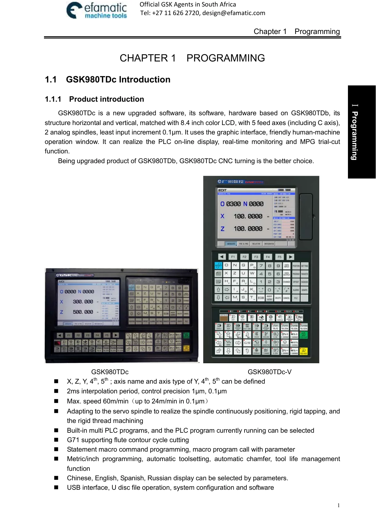
For programming work, the manual documents the command structure needed to write and check part programs on the GSK980TDc. It explains absolute and incremental programming, diameter and radius programming, rapid traverse and linear interpolation, circular interpolation with R or I and K, three-point arcs, ellipse and parabola interpolation, plane selection, polar coordinate interpolation, cylindrical interpolation, chamfering, dwell, reference point return, skip interpolation, automatic tool offset, workpiece and local coordinate systems, fixed cycles, multiple roughing and finishing cycles, grooving cycles, thread cutting cycles, rigid tapping, constant surface speed control, feed per minute and feed per revolution, additional axis motion, and macro commands. The G-code reference is useful when checking existing programs, adapting a program for a different workpiece, or tracing why a cycle behaves differently from the drawing.
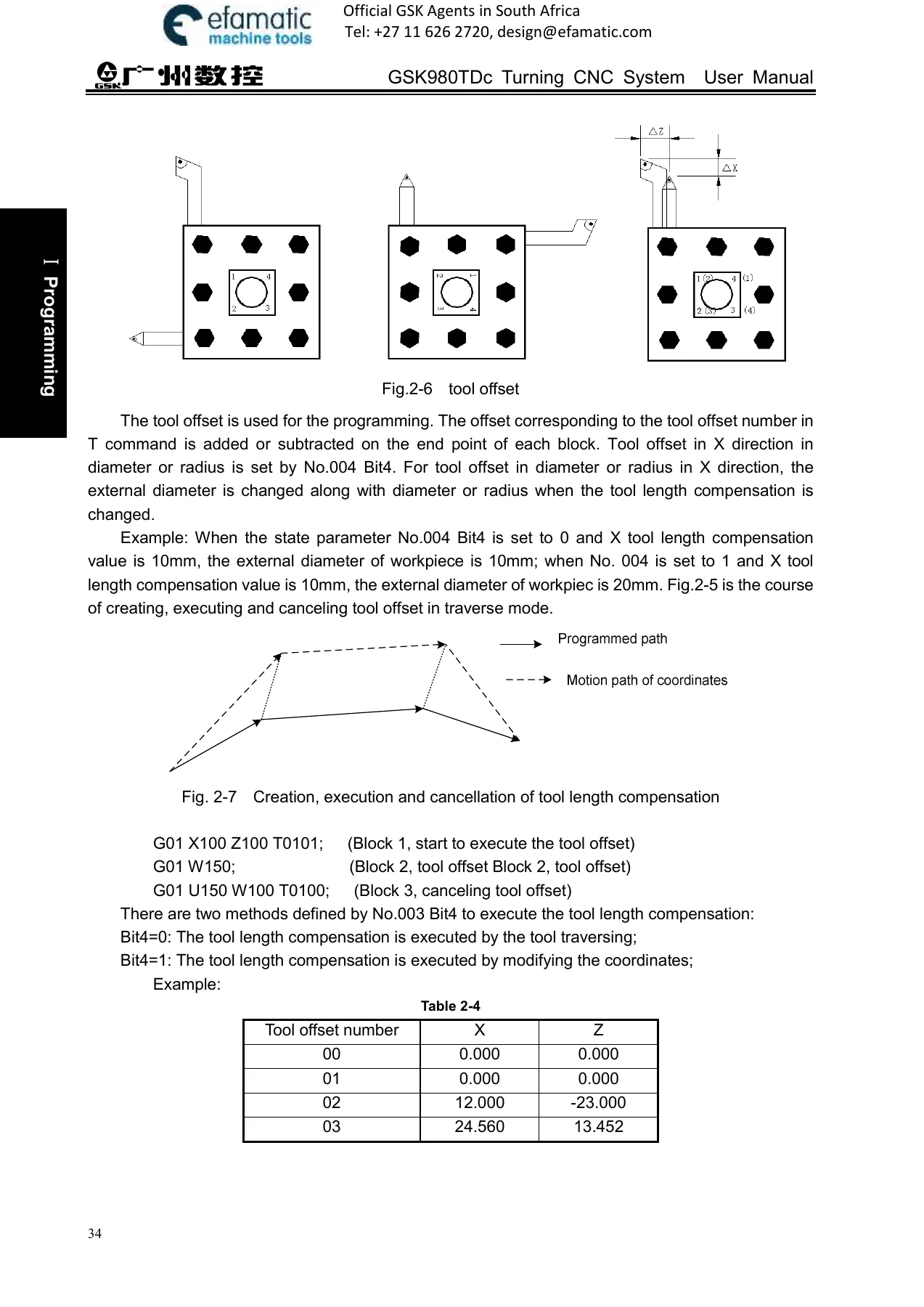
For setup and operation, the GSK980TDc Turning CNC Programming Operation Installation Connection User Manual covers the display and keypad organization, mode selection, manual feed and rapid traverse, spindle and cooling control, tool change, offset and wear setting, trial toolsetting, machine zero return, program zero return, program creation and editing, program search and management, MDI block input and execution, automatic run controls, single block, dry run, machine lock, MST lock, block skip, MPG trial-cut, parameter access, file management, data backup and resume, and communication with GSKComm. The operation chapters are written around the system interface and the standard PLC key functions, with notes that machine panel keys are ultimately defined by the machine builder’s PLC program.
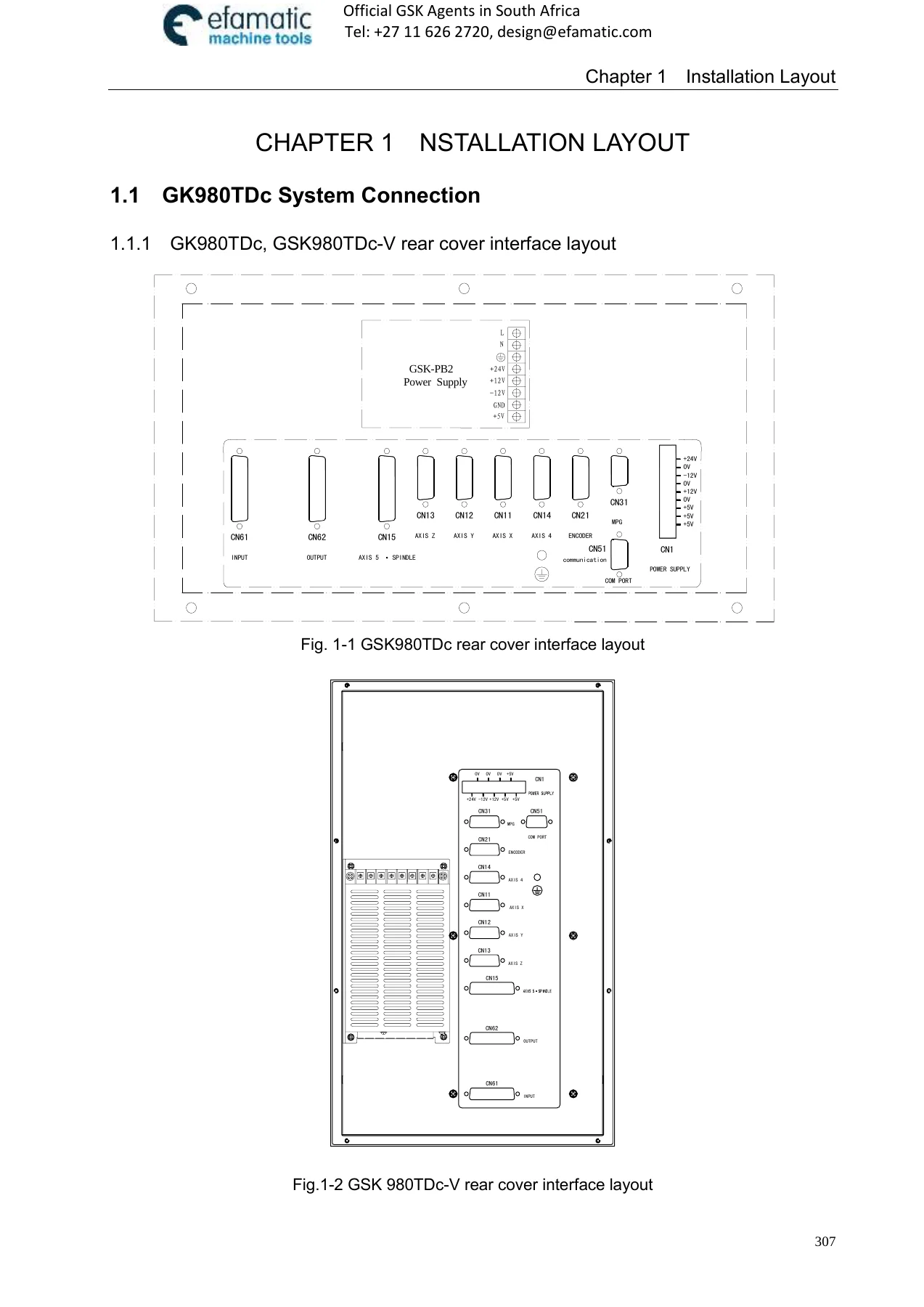
For installation and maintenance, the manual includes interface definitions and connection examples for drive units, spindle encoders, MPG, spindle inverter, PC communication, power supply, and I/O signals. It documents stroke limits, emergency stop, tool change control, machine zero return signal sequences, spindle control, automatic gearing, eight-point orientation, Cs axis control, multiple spindle functions, rigid tapping, chuck and tailstock control, safety door detection, external override, and external MPG. The parameter and diagnosis chapters support machine debugging, drive configuration, gear ratio adjustment, acceleration and deceleration tuning, spindle adjustment, backlash measurement, tool post debugging, and pitch error compensation. The alarm and diagnosis message sections help narrow down PLC, CNC, and machine-side signal faults.
The GSK980TDc Turning CNC Programming Operation Installation Connection User Manual – Efamatic Edition PDF is relevant to technicians, machine setters, maintenance staff, and advanced operators who need the documented command formats, interface pinouts, parameter descriptions, signal checks, and setup procedures for the GSK980TDc and GSK980TDc-V turning CNC systems. It is a reference for writing and checking turning programs, configuring a machine after installation, adjusting spindle and axis behavior, setting tool offsets, investigating alarms, and verifying PLC and CNC signal states. Because the manual contains both programming and connection-level detail, it can support work that spans from part program development to electrical checkout and machine commissioning.
IMAGES PREVIEW
Having the correct GSK980TDc programming, operation, installation, and connection information in one PDF makes it easier to follow the documented command syntax, parameter meanings, signal states, and setup steps instead of relying on incomplete notes. The file is delivered as an instant PDF download after payment, with no shipping, and can be stored on a computer, tablet, or phone for reference in the workshop or office. Pages can be printed when a bench copy of the programming, parameter, or interface section is needed.
Reviews
There are no reviews yet.