
Hangcha XE Series CPD15-50 Electric Forklift Truck Maintenance Manual 2024 PDF
Original price was: $44.95.$26.95Current price is: $26.95.
Complete 2024 Hangcha XE series electric forklift maintenance manual for CPD15-50 lithium-ion models, covering battery, transmission, brakes, hydraulics, mast, controllers and full electrical schematics.
Description
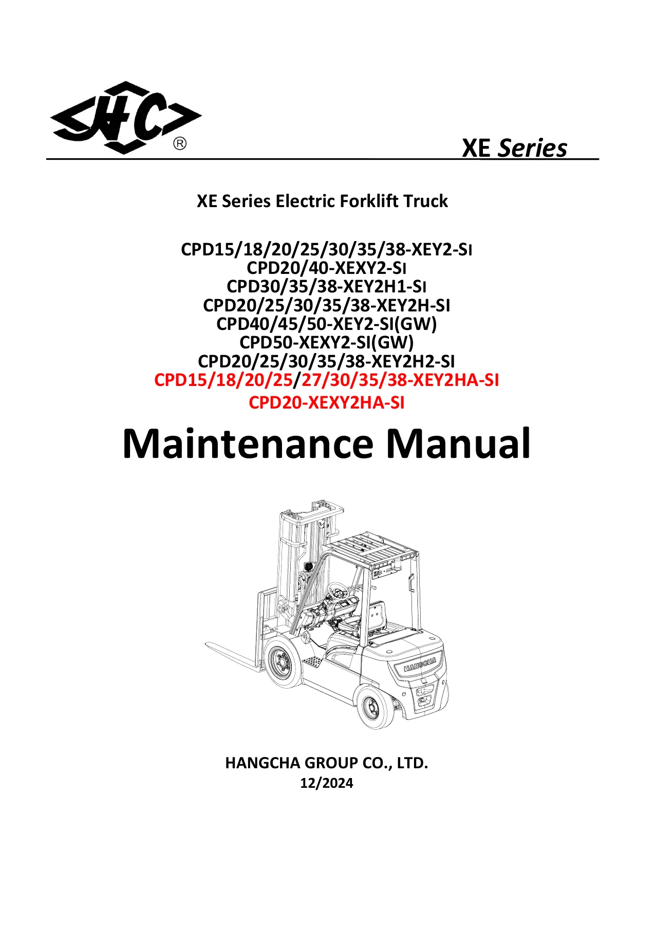
Hangcha XE Series CPD15-50 Electric Forklift Truck Maintenance Manual
This Hangcha XE Series CPD15-50 Electric Forklift Truck Maintenance Manual is the complete workshop reference for the 2024 XE series four-wheel electric forklift range. Published by Hangcha Group Co., Ltd. in December 2024, it documents maintenance, disassembly, assembly, adjustment and fault diagnosis for the 1.5t to 5.0t lithium-ion models built on Hangcha’s dedicated lithium-ion battery architecture and permanent magnet synchronous technology. Operators, fleet managers and trained service personnel are the intended audience, and the procedures are written to be worked through on the shop floor rather than skimmed as theory.
File Details
- Manual type: Maintenance / Workshop Manual
- Brand: HANGCHA (HANGCHA GROUP CO., LTD.)
- Series: XE Series four-wheel electric forklift truck
- Capacity range: 1.5t – 5.0t
- Language: English
- Publication date: 12/2024
- File format: PDF
Chapters Covered
The manual is organised into fourteen top-level chapters, each opening with structure diagrams and closing with fault diagnosis or troubleshooting tables:
- 1. Lithium-ion battery – usage precautions, structure and size, charging socket interfaces, daily and regular maintenance, internal components, module assembly, electrical panel assembly, wire harness assembly, BMS assembly, fault diagnosis and full battery disassembly
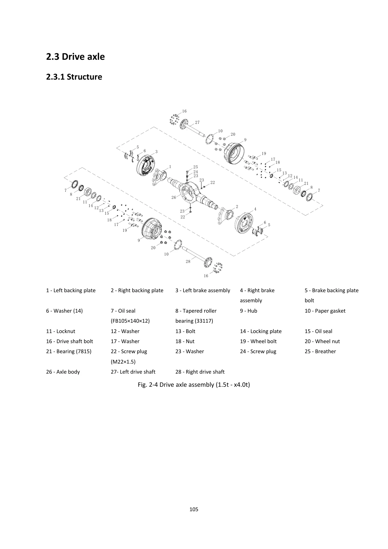
- 2. Transmission system – overview, disassembly of the transmission assembly, drive axle, gearbox and differential, tires
- 3. Steering device and steering axle – steering column and wheel, steering axle structure, main data, disassembly and adjustment, steering cylinder
- 4. Braking system – service brake, brake master cylinder, hand brake, brake shoe and drum service, electromagnetic brake, fault diagnosis
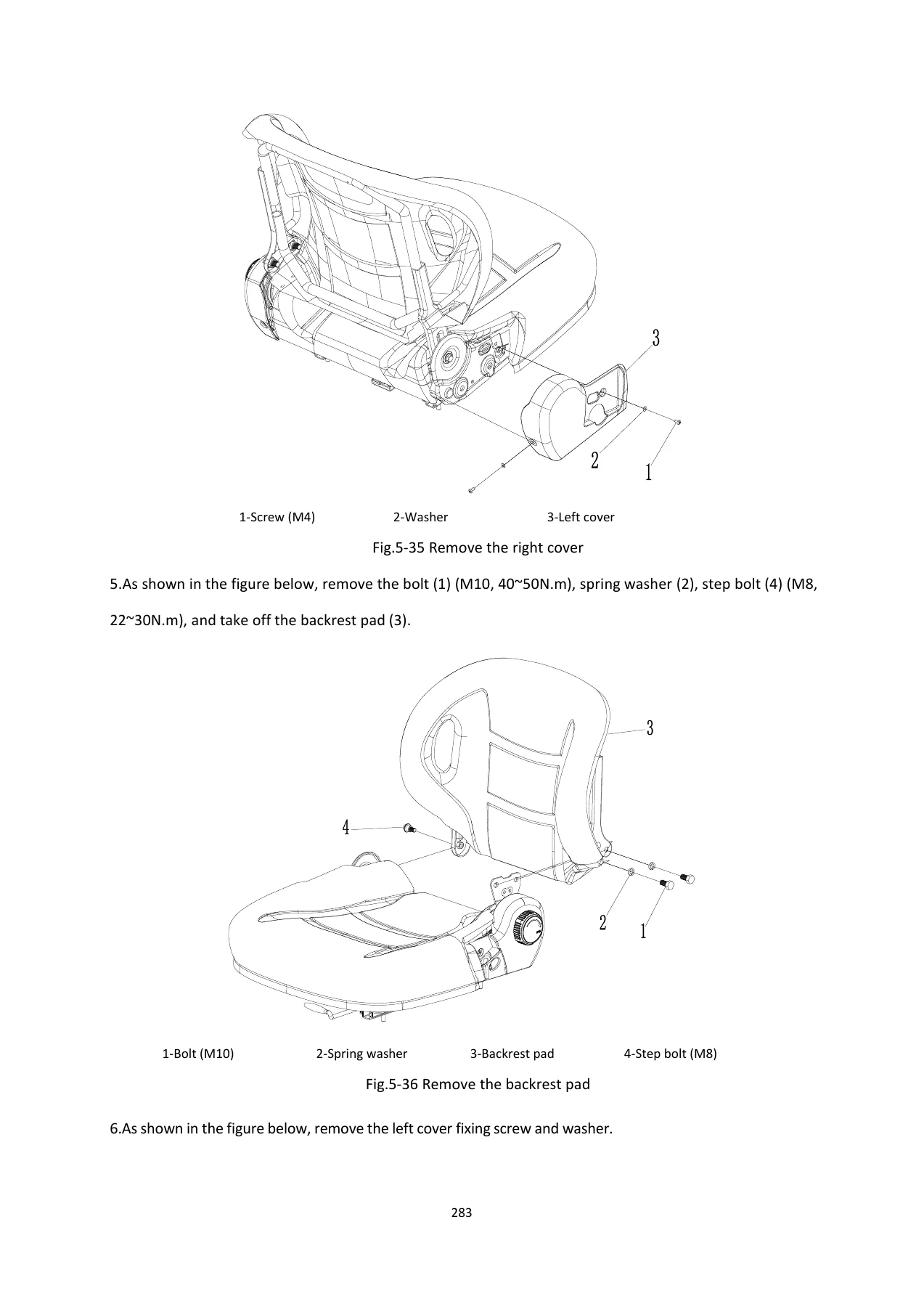
- 5. Truck body – dashboard assembly, machine hood and floor assembly, battery clamping device, counterweight, overhead guard, seat
- 6. Hydraulic system – oil pump device, oil pump gearbox, gear pump, multi-way valve, hydraulic oil lines, oil tank, electromagnetic proportional control valve, priority valve, steering gear, fault diagnosis
- 7. Motor – traction motor and oil pump motor specifications, motor maintenance, disassembly precautions, speed and temperature sensor replacement
- 8. Mast – overview, adjustment parameters, main structural components, disassembly and adjustment of the lifting assembly, fault diagnosis
- 9. Controller – MC3808 controller features, traction controller fault codes (E1 series), oil pump controller fault codes (E3 series), troubleshooting, Enpower controller parameters, disassembly and assembly
- 10. Electrical components – dashboard, lighting system, switches, fuses, DC-DC converter, brake light switch, emergency stop button, fan assembly, relays, electronic flasher
- 11. Schematic diagrams – braking, hydraulic and full electrical schematics by model
- 12. Cab – overhead guard, door assembly, rear window, front windshield, fan, cab electrical schematic
- 13. Main accessories – thumb switch and armrest system, attachments including CS17C and CS17D side shift fork positioners
- 14. Bolts Tightening Torque Table
What the document delivers is a full service ecosystem for the XE series. The lithium-ion chapter alone carries the battery management system, contactor and relay layout, shunt and pre-charge circuits, module stacking sequences and the tightening torques and threadlocker callouts required to reassemble the pack correctly. The transmission and drive axle chapters give exploded diagrams with named components, torque tables by tonnage class and bearing preload or axial clearance targets. The controller chapter cross-references fault code numbers to causes and step-by-step troubleshooting logic, so a technician can follow a live fault from symptom to component rather than guessing.
Models Covered
The manual applies to the following XE series model designations:
- CPD15/18/20/25/30/35/38-XEY2-SI
- CPD20/40-XEXY2-SI
- CPD30/35/38-XEY2H1-SI
- CPD20/25/30/35/38-XEY2H-SI
- CPD40/45/50-XEY2-SI(GW)
- CPD50-XEXY2-SI(GW)
- CPD20/25/30/35/38-XEY2H2-SI
- CPD15/18/20/25/27/30/35/38-XEY2HA-SI
- CPD20-XEXY2HA-SI
Systems and Tasks This Manual Supports
Because the XE platform spans several battery capacities and two motor families, the manual separates procedures by tonnage band wherever clearances, torques or assembly sequences differ. Drive axle tightening torques are given separately for 1.5t – small 2t, 2.0t – 2.5t, 3.0t – x4.0t and 4.0t – 5.0t classes, and the same model-specific approach runs through the gearbox, steering axle and mast chapters.
Battery service is documented at an unusual level of detail: pack removal from the truck, upper cover removal, DC-DC connector disassembly, discharge harness and communication socket removal, pre-charge relay and resistor removal, shunt removal, thermal relay wiring, charging socket replacement and full module removal with polarity marking rules. Component-level replacement procedures are given for the BMS, fuse, relay and charging socket, along with the A-B-A test method for diagnosing suspected BMS faults.
The hydraulic chapter covers the oil pump device, JS06H and JS08H series pump gearboxes, gear pump variants from multiple suppliers, the two-, three- and four-section multi-way valves, priority valve, fully hydraulic steering gear, tilt cylinder pipelines and the oil tank. Pressure adjustment of the main safety valve is described step by step with gauge connection, normal pressure ranges and locknut tightening guidance.
Electrical coverage is delivered in two ways: as component-level disassembly and test procedures in Chapter 10, and as complete model-specific schematics in Chapter 11. Dashboard fault codes, fuse positions, fusible wire cautions and relay pin definitions are all present, which makes this manual usable for both mechanical repair and electrical diagnosis on the same truck.
Who This Manual Is For
This is a maintenance manual written for trained and approved service personnel. It assumes familiarity with high-voltage lithium-ion systems, hydraulic circuits and permanent magnet motor controllers. Buyers should note it is a service and maintenance document, not an operator’s guide and not a parts catalogue; it explains how to diagnose, remove, repair, adjust and refit components, and it references the truck’s separate Operation and Maintenance Manual for some routine items such as tire disassembly.
Why This Manual Matters
Lithium-ion electric forklifts combine high-voltage battery management, permanent magnet synchronous motors and load-sensing hydraulics in one machine, and each of those systems has its own torque, clearance and safety requirements. Working from generic guidance risks incorrect pre-charge handling, damaged seals, wrong relay wiring or an incorrectly torqued module busbar. The Hangcha XE Series CPD15-50 Electric Forklift Truck Maintenance Manual supplies the manufacturer’s own figures: busbar torques of 12Nm at module and output terminals, 4.8Nm on BMS and thermal relay bolts, 65 – 70Nm on gearbox housing bolts, drive axle wheel nut values by class, mast tilt angles and chain slack settings. It also spells out the safety sequencing that keeps a technician safe around a live high-voltage pack.
Instant PDF Delivery
The manual is delivered as a PDF download immediately after purchase. There is no shipping, no waiting for a physical book, and no risk of a used copy missing pages. The file opens on any laptop, tablet or phone and every page can be printed for use in the workshop, so you can keep a clean copy on the screen while the printed pages take the grease. Whether you are replacing a BMS, resealing a lift cylinder, resetting controller parameters or chasing a fault code through the traction controller, the Hangcha XE Series CPD15-50 Electric Forklift Truck Maintenance Manual 2024 gives you the procedure, the values and the diagram in one place.
Reviews
There are no reviews yet.