
★ TRUSTED BY 321,897+ PROFESSIONALS WORLDWIDE
🏢
Trusted Business
Verified & Licensed
🛡️
Virus Free Files
100% Safe Downloads
🔒
Secure Payment
SSL Protected
Instant Delivery
Available Immediately
Sale!

HEIDENHAIN TNC 320 Technical Manual – NC Software 340 55x-04 – Machine Builder Integration & PLC Manual

Original price was: $34.95.Current price is: $19.95.

Complete HEIDENHAIN TNC 320 Technical Manual covering NC software 340 55x-04. This 1,427-page machine-builder-level reference details electrical installation, machine parameters, axis/spindle configuration, PLC programming, and data interfaces for integrating the TNC 320 control onto a machine tool.

Instant PDF Download
Available immediately
💾
Save to Your Device
Download & keep forever
🛡️
Antivirus Scanned
100% virus-free
🌍
Trusted Worldwide
175,000+ customers

Description

HEIDENHAIN TNC 320 Technical Manual – NC Software 340 55x-04

This HEIDENHAIN TNC 320 Technical Manual is the full machine-builder documentation for NC software version 340 55x-04, dated October 2010. Unlike an operator’s handbook, this TNC 320 Technical Manual is written for machine manufacturers, integrators, and service engineers who mount, wire, configure, and commission the TNC 320 control on a machine tool.

File Details

  • Manual type: Technical Manual (machine builder / integrator documentation)
  • Brand / Control: HEIDENHAIN TNC 320
  • NC Software: 340 55x-04
  • Edition date: October 2010
  • Language: English
  • Page count: 1,427 pages
  • File format: PDF, instant download

IMAGES PREVIEW

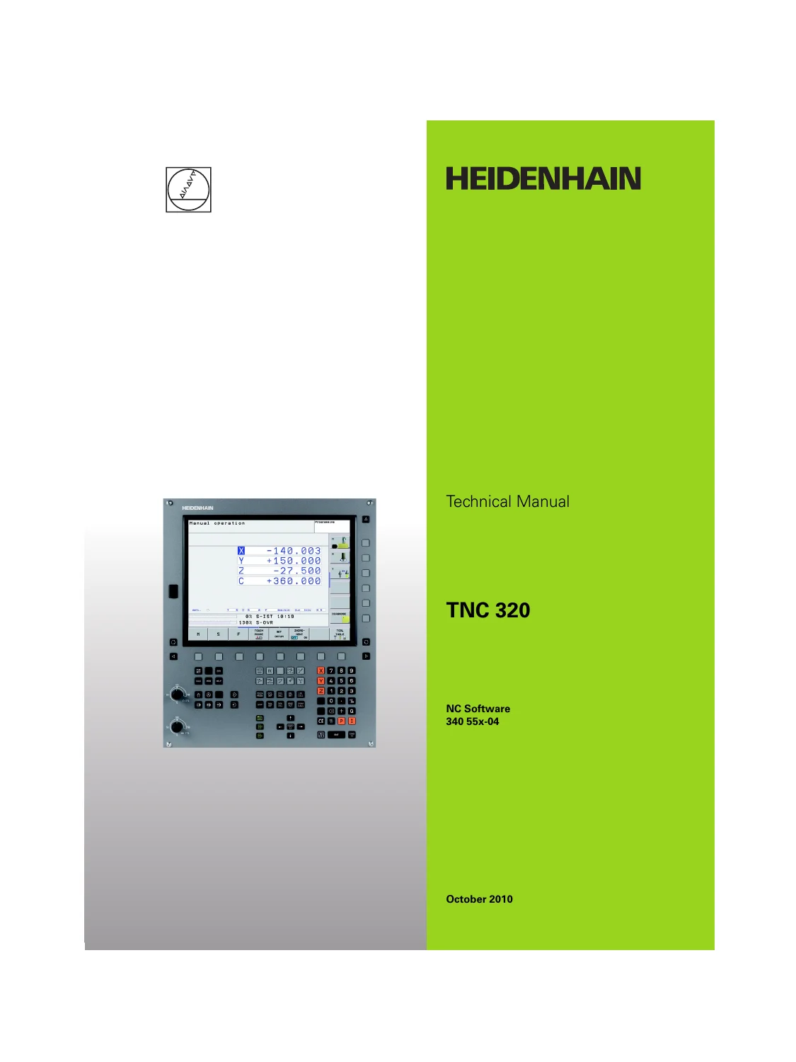
HEIDENHAIN TNC 320 Technical Manual - NC Software 340 55x-04 - Machine Builder Integration & PLC Manual — PDF page 1 preview
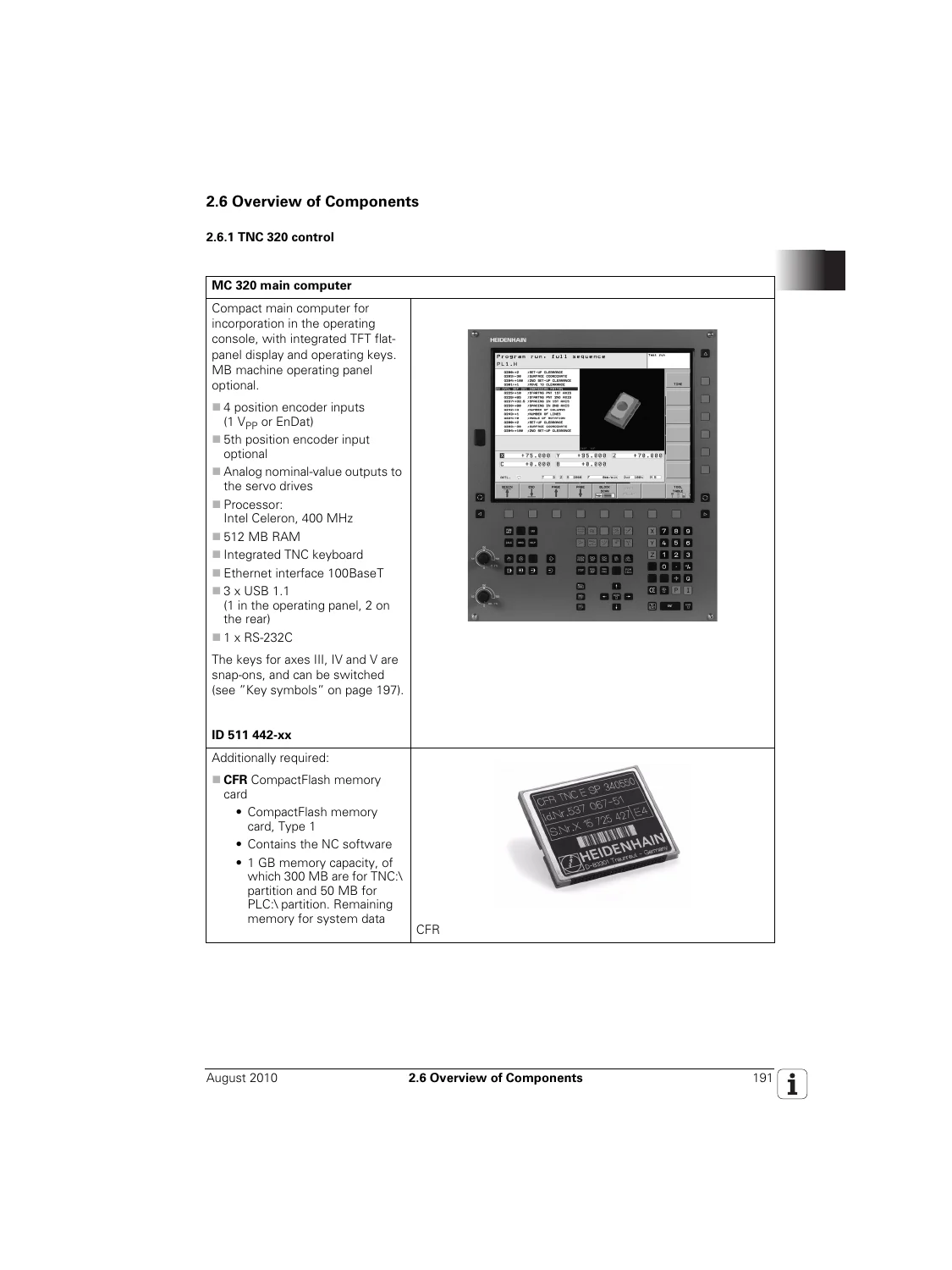
HEIDENHAIN TNC 320 Technical Manual - NC Software 340 55x-04 - Machine Builder Integration & PLC Manual — PDF page 191 preview
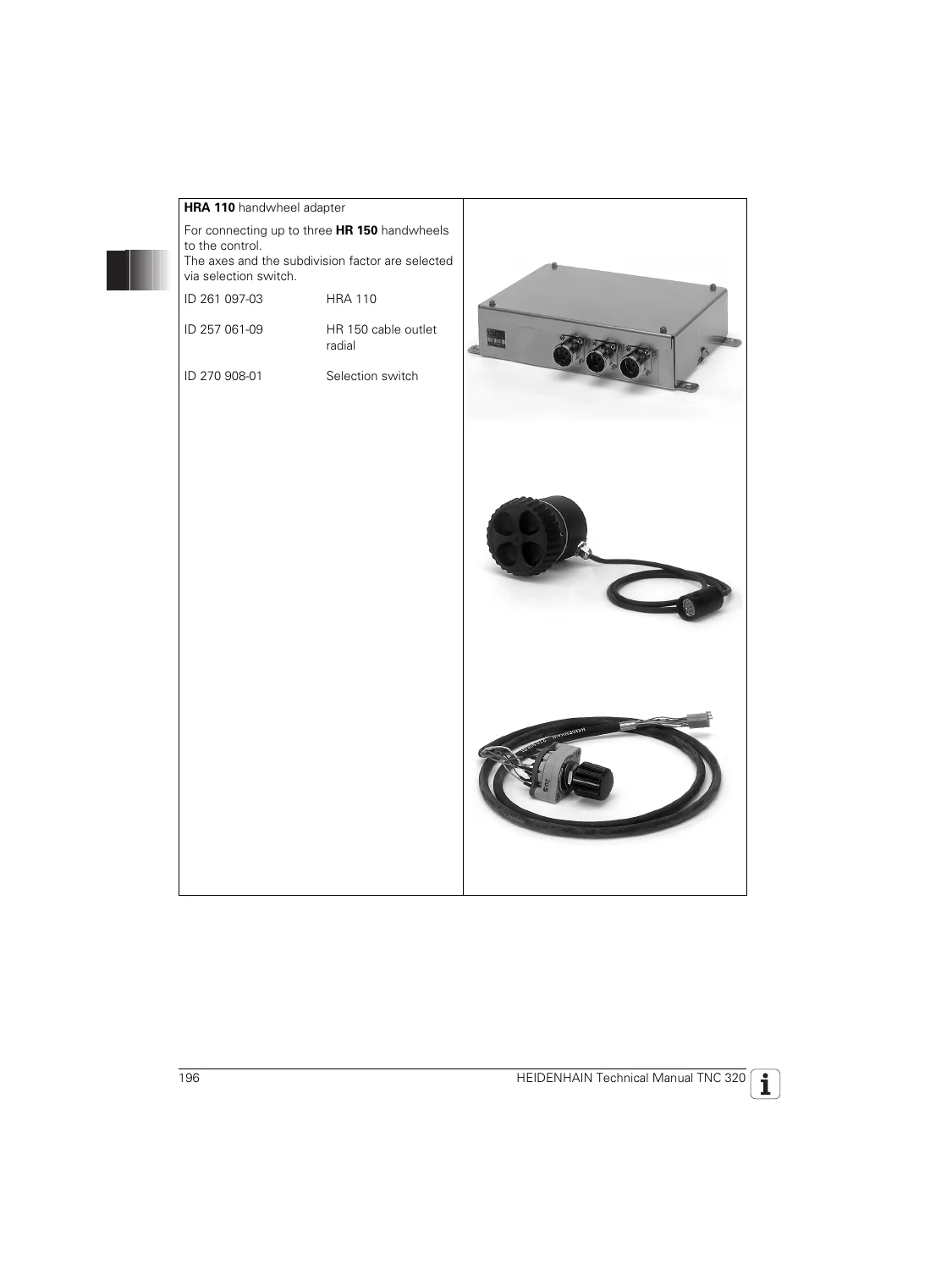
HEIDENHAIN TNC 320 Technical Manual - NC Software 340 55x-04 - Machine Builder Integration & PLC Manual — PDF page 196 preview

Chapters Covered

  • Update Information (Update Info No. 1-4, NC software 340 551-xx feature history)
  • Introduction – symbols, components, TNC 320 control overview, MB 420 operating panel, handwheels, touch probes, software designation
  • Mounting and Electrical Installation – safety, EMC, environmental conditions, connection overview, power supply, encoder connections, PLC inputs/outputs, USB interface, dimensions, grounding and cable overview
  • Machine Parameters – configuration editor, user parameters, KeySynonym function, parameter file structure, machine-parameter subfiles, full MP number overview and iTNC 530 to TNC 320 MP cross-reference
  • Modules and PLC Operands
  • Configuring the Axes and Spindle – machine structure, machining channel configuration, axis designations, encoders, analog axes, axis error compensation, machine kinematics, tilting axes, synchronized (gantry) axes, reference marks, control loop
  • Machine Integration – keystroke simulation, electronic handwheel, override devices, PLC inputs/outputs, tool changer, touch probe cycles, commissioning of analog axes, Online Monitor (OLM) diagnosis
  • PLC Programming – PLC functions, API 3.0 symbolic memory interface, operands, data organization, M functions, string processing, submit programs, program structures, PLC modules
  • Data Interfaces – Ethernet, USB 1.1, serial RS-232-C/V.24, data transmission protocols, TeleService 2.0, PLC data transfer
  • Index

Complete PDF Bookmark Tree

Complete Bookmarks

The complete bookmarks in the “HEIDENHAIN TNC 320 Technical Manual – NC Software 340 55x-04 – Machine Builder Integration & PLC Manual” are as follows:

Contensp. 3
1 Update Informationp. 17
1.1 General Informationp. 17
1 Update Information No. 1p. 19
1.1 Overviewp. 19
1.1.1 Released Service Packsp. 19
1.1.2 Released NC Softwarep. 19
1.2 NC Software 340 551-xxp. 20
1.2.1 Description of the New Functionsp. 32
1 Update Information No. 2p. 99
1.1 Overviewp. 99
1.1.1 Released Service Packsp. 99
1.1.2 Released NC Softwarep. 99
1.2 NC Software 340 551-02p. 100
1.3 NC Software 340 551-03p. 101
1.3.1 Overview of the New Functionsp. 101
1.3.2 Upgrade Functions (Feature Content Level)p. 161
1.4 NC Software 340 554-xx (TNC 320 Programming Station)p. 162
1.4.1 Description of the New Functionsp. 162
1.5 Hardwarep. 163
1.5.1 MC 320 Main Computerp. 163
1.5.2 CFR TNC 320 Memory Cardp. 164
1 Update Information No. 3p. 165
1.1 Overviewp. 165
1.1.1 Released Service Packsp. 165
1.1.2 Released NC Softwarep. 165
1.2 NC Software 340 551-03p. 165
1.3 NC Software 340 551-04 / NC Software 340 560-02p. 166
1.3.1 Important Notes on Updating Softwarep. 166
1.3.2 Description of the New Functionsp. 170
1.4 NC Software 340 554-xx (TNC 320 Programming Station)p. 184
1.4.1 Description of the New Functionsp. 184
1 Update Information No. 4p. 185
1.1 Overviewp. 185
1.1.1 Released service packsp. 185
1.2 NC Software 340 551-04 Service Pack 8p. 186
1.2.1 Description of important changesp. 186
1.3 Hardwarep. 187
1.3.1 MC 320 main computer of the TNC 320p. 187
2 Introductionp. 189
2.1 Meaning of the Symbols Used in this Manualp. 189
2.2 Proper Operationp. 189
2.3 Trained Personnelp. 189
2.4 General Informationp. 190
2.5 Definition of Termsp. 190
2.6 Overview of Componentsp. 191
2.6.1 TNC 320 controlp. 191
2.6.2 MB 420 machine operating panelp. 193
2.6.3 Handwheelsp. 194
2.6.4 Key symbolsp. 197
2.6.5 Touch probesp. 201
2.6.6 Other accessoriesp. 205
2.6.7 Documentationp. 206
2.7 Brief Descriptionp. 207
2.8 Hardwarep. 213
2.8.1 Designation of the logic unitp. 213
2.9 Softwarep. 214
2.9.1 Designation of the softwarep. 214
2.9.2 PLC softwarep. 214
2.9.3 Enabling additional axes or software optionsp. 215
2.9.4 Upgrade functions (Feature Content Level)p. 219
2.9.5 NC software exchange on the TNC 320p. 220
2.9.6 Installing a service packp. 225
2.9.7 Reversing a software updatep. 226
2.9.8 Data backupp. 227
2.9.9 Monitoring hardware changesp. 227
2.9.10 Window manager (XFCE)p. 228
2.10 Software Releasesp. 232
2.10.1 NC software 340 551-xxp. 232
3 Mounting and Electrical Installationp. 237
3.1 General Informationp. 237
3.1.1 Safety precautionsp. 237
3.1.2 Degrees of protectionp. 238
3.1.3 Electromagnetic compatibilityp. 238
3.1.4 ESD protectionp. 239
3.2 Environmental Conditionsp. 241
3.2.1 Heat generation and coolingp. 241
3.2.2 Humidityp. 241
3.2.3 Installation elevationp. 241
3.2.4 Mechanical vibrationp. 241
3.2.5 Mounting positionp. 242
3.3 Connection Overview for TNC 320p. 243
3.3.1 MC 320 main computerp. 243
3.4 Power Supply for the MC 320p. 244
3.5 Power Supply for PLC Outputsp. 245
3.5.1 Power supply for PL 510p. 246
3.6 Power Supply for Control-Is-Ready Signalp. 246
3.7 Buffer Batteryp. 247
3.8 Encoder Connectionsp. 248
3.8.1 General informationp. 248
3.8.2 Position encoder inputp. 249
3.9 Adapters for Encoder Signalsp. 251
3.10 Analog Inputp. 255
3.11 Analog Nominal Value Outputp. 258
3.11.1 Nominal value outputp. 258
3.12 Touch Probe Systemsp. 261
3.12.1 Triggering touch probe for workpiece measurementp. 261
3.13 Data Interfacesp. 265
3.14 Handwheel Inputp. 268
3.14.1 HR 410 portable handwheelp. 269
3.14.2 HR 130 panel-mounted handwheelp. 271
3.14.3 HRA 110 handwheel adapterp. 271
3.15 Switching Inputs 24 V- (PLC)p. 273
3.15.1 Input signals and addressesp. 273
3.15.2 PLC inputs on the PL 510p. 276
3.16 Switching Outputs 24 V- (PLC)p. 279
3.17 PLC Input/Output Unitsp. 283
3.17.1 PL 510p. 283
3.18 Machine Operating Panelp. 286
3.19 USB Interfacep. 289
3.20 Cable Specificationsp. 290
3.21 Dimensionsp. 291
3.21.1 MC 320p. 292
3.21.2 MB 420p. 293
3.21.3 PL 510p. 294
3.21.4 Adapter block for the data interfacep. 295
3.21.5 USB hubp. 296
3.21.6 Line-drop compensatorp. 297
3.21.7 Handwheelsp. 298
3.21.8 Touch probesp. 301
3.22 Grounding Diagram for TNC 320p. 307
3.23 Cable Overview for TNC 320p. 309
3.24 Cable Overview for TNC 320-Accessoriesp. 310
4 Machine Parametersp. 311
4.1 General Informationp. 311
4.2 The “Machine Parameter” Mode of Operationp. 313
4.2.1 Calling the configuration editorp. 313
4.2.2 Entering and changing machine parametersp. 315
4.2.3 Accessing machine parameters via MP numbersp. 325
4.2.4 Managing configuration filesp. 328
4.2.5 Sort file contentp. 328
4.2.6 Attribute informationp. 329
4.2.7 Access protection / Optionsp. 331
4.2.8 Update rulesp. 332
4.2.9 Remove syntax errorp. 341
4.2.10 Resets the update versionp. 341
4.2.11 Backup of parametersp. 342
4.3 User Parametersp. 343
4.3.1 Configuration of the user parametersp. 344
4.3.2 Example:p. 346
4.3.3 XML commands for creating the layout filesp. 348
4.4 The KeySynonym Functionp. 351
4.5 Allocation of Configuration Datap. 353
4.6 Structure of a Parameter Filep. 355
4.7 Machine-Parameter Subfilesp. 358
4.7.1 Syntax of machine-parameter subfilep. 358
4.7.2 Activating the machine-parameter subfilep. 358
4.7.3 Displaying/editing data records in the configuration editorp. 361
4.8 Read or Change Machine Parameters via a PLC Modulep. 363
4.9 Overview of Machine Parametersp. 369
4.9.1 “System” groupp. 369
4.9.2 “Channels” groupp. 378
4.9.3 “Axes” groupp. 382
4.9.4 “KeySynonym” groupp. 385
4.10 Parameter Overview Sorted by MP Numbersp. 386
4.10.1 System configuration and miscellaneousp. 387
4.10.2 Channel-specific parametersp. 407
4.10.3 Axis-specific parametersp. 412
4.10.4 Parameters for configuring the parameter setsp. 414
4.11 Overview: iTNC 530 MP Numbers TNC 320 MP Numbersp. 421
4.11.1 Measuring systems and machine axesp. 421
4.11.2 Positioning and regulationp. 424
4.11.3 PWM interface (DSP)p. 426
4.11.4 Spindle control (1st spindle)p. 429
4.11.5 Integrated PLCp. 430
4.11.6 Serial interfacep. 431
4.11.7 Touch probep. 431
4.11.8 Tool touch probe for tool measurementp. 432
4.11.9 Tappingp. 432
4.11.10 Display and programmingp. 433
4.11.11 Machining and Program Runp. 434
4.11.12 Hardwarep. 435
5 Modules and PLC Operandsp. 437
5.1 Overview of Modulesp. 437
5.2 Overview of the PLC Operandsp. 442
5.2.1 PLC operands of the General Data groupp. 442
5.2.2 PLC operands of the Operating Mode Group groupp. 444
5.2.3 PLC operands of the Machining Channels groupp. 445
5.2.4 PLC operands of the Axis groupp. 447
5.2.5 PLC operands of the Spindle groupp. 449
6 Configuring the Axes and Spindlep. 451
6.1 Machine Structurep. 451
6.1.1 Adapting the control to the machinep. 451
6.1.2 Definition of axesp. 452
6.2 Configuration of Machining Channelsp. 454
6.2.1 Configuring a machining channelp. 454
6.2.2 Traversing the reference marksp. 459
6.2.3 Returning to the contour/block scanp. 460
6.3 Configuration of Axesp. 464
6.3.1 Axis designations and coordinatesp. 466
6.3.2 Programmable axesp. 469
6.3.3 Physical axesp. 472
6.3.4 Display of axes on the screenp. 480
6.3.5 Hirth couplingp. 484
6.3.6 Kinematics properties of axesp. 486
6.3.7 Manual axis (counter axis)p. 488
6.3.8 Introducing a new NC axis into the systemp. 490
6.4 Encodersp. 501
6.4.1 Type of the position encoderp. 501
6.4.2 Signal period of encodersp. 504
6.4.3 Distance-coded reference marksp. 506
6.4.4 Encoder connectionsp. 507
6.4.5 Defining the traverse directionp. 510
6.4.6 Encoder monitoringp. 512
6.5 Analog Axesp. 516
6.5.1 Central drivep. 517
6.6 Reading and Writing Axis Informationp. 519
6.6.1 Reading axis informationp. 519
6.6.2 Writing axis information-activating and deactivating axesp. 525
6.7 Traverse Rangesp. 534
6.7.1 Overwrite software limit switchesp. 535
6.8 Lubrication Pulsep. 536
6.9 Controlling Axes by PLC (PLC Axes)p. 537
6.10 Axis Error Compensationp. 547
6.10.1 Backlash compensationp. 548
6.10.2 Linear axis error compensationp. 552
6.10.3 Nonlinear axis error compensationp. 554
6.10.4 Compensation of thermal expansionp. 561
6.11 Machine Kinematicsp. 563
6.11.1 Configuring the machine kinematicsp. 566
6.11.2 Find/activate kinematics through the PLCp. 584
6.12 Machine Kinematics Up to HEIDENHAIN NCK Software Version 597 110-02p. 586
6.12.1 Configuration of the machine kinematicsp. 586
6.12.2 Definition of the transformation with vectorsp. 595
6.13 Tilting Axesp. 599
6.13.1 “Tilting the working plane” function (software option 1)p. 599
6.14 Parallel Axesp. 605
6.15 Synchronized Axes (Option 24)p. 607
6.15.1 Gantry axesp. 607
6.16 Reference Marksp. 617
6.16.1 Definitionp. 617
6.16.2 Traversing the reference marksp. 618
6.16.3 Defining the process of traversing the reference marksp. 621
6.16.4 “Pass Over Reference Point” operating modep. 628
6.17 The Control Loopp. 631
6.17.1 Block diagram of analog controlp. 631
6.17.2 Relation between jerk, acceleration, velocity and distancep. 632
6.17.3 Look-aheadp. 634
6.17.4 Interpolatorp. 644
6.17.5 Nominal position value filterp. 645
6.17.6 Position controllerp. 656
6.17.7 Activating and deactivating position control loopsp. 665
6.17.8 Feed-rate enablep. 668
6.17.9 Controller parameters for manual traversep. 669
6.17.10 Controller parameters for analog axesp. 670
6.17.11 Switching parameter setsp. 682
6.18 Monitoring Functionsp. 693
6.18.1 Monitoring the drivesp. 693
6.18.2 Position monitoringp. 695
6.18.3 Movement monitoringp. 699
6.18.4 Standstill monitoringp. 701
6.18.5 Positioning windowp. 702
6.18.6 Temperature monitoringp. 706
6.18.7 Status of HEIDENHAIN hardware and softwarep. 707
6.18.8 Emergency stop monitoringp. 709
6.19 Spindlesp. 712
6.19.1 Configuring spindlesp. 712
6.19.2 Position encoder of the spindlep. 713
6.19.3 Filtering the acceleration valuesp. 714
6.19.4 Controlling the spindlep. 715
6.19.5 Oriented spindle stop (spindle point stop)p. 727
6.19.6 Tapping with floating tap holder and coded spindle-speed outputp. 731
6.19.7 Switching the modes of operationp. 733
6.19.8 Stop spindle at trip dog positionp. 735
6.19.9 Analog spindle with unipolar motorp. 738
6.19.10 Spindle of the kinematics modelp. 739
6.19.11 Gear shiftingp. 740
6.19.12 Tappingp. 740
6.19.13 Operating a second spindlep. 741
6.19.14 C-axis operationp. 742
6.19.15 Volts-per-hertz control modep. 744
6.20 Integrated Oscilloscopep. 745
6.20.1 Fundamentalsp. 745
6.20.2 Prepare recordingp. 747
6.20.3 Record signalsp. 751
6.20.4 Analyze recordingp. 753
6.20.5 Saving and loading recordingsp. 756
6.20.6 Circular interpolation test with the integrated oscilloscopep. 757
6.20.7 Configure the colors of the oscilloscope displayp. 758
7 Machine Integrationp. 761
7.1 Display and Operationp. 761
7.1.1 Position and status displayp. 761
7.1.2 Unit of measurement for display and operationp. 769
7.1.3 Conversational languagep. 770
7.1.4 Format of NC programs and cycle displayp. 773
7.1.5 Settings for the programming mode of operationp. 775
7.1.6 Binary file managementp. 781
7.1.7 Access rights to drives and directoriesp. 783
7.1.8 Code numbersp. 785
7.1.9 Programming station modep. 786
7.1.10 Operating modes / control operation in the operating mode groupp. 789
7.1.11 Control operation in the machining channelp. 793
7.1.12 Error messages and log filesp. 810
7.1.13 TNCguide – context-sensitive help system (user documentation)p. 835
7.1.14 Table editorp. 846
7.1.15 Machine datump. 849
7.1.16 Cyclesp. 852
7.1.17 Window manager (XFCE)p. 856
7.2 Small PLC windowp. 861
7.3 PLC Soft Keysp. 865
7.4 Switching the Control On/Offp. 866
7.4.1 Powering up the controlp. 866
7.4.2 Shutting down the controlp. 869
7.5 Keystroke Simulationp. 877
7.5.1 Control keyboardp. 877
7.5.2 Machine operating panelp. 884
7.6 Electronic Handwheelp. 885
7.6.1 Serial handwheelp. 885
7.6.2 Handwheel at position encoder inputp. 890
7.6.3 Traverse per handwheel revolutionp. 895
7.6.4 Assigning a handwheel to an axisp. 896
7.6.5 HR 410 portable handwheelp. 899
7.6.6 HR 150 panel-mounted handwheels with HRA 110 handwheel adapterp. 901
7.7 Overridep. 903
7.7.1 Override devicesp. 903
7.7.2 Compensation for potentiometersp. 905
7.7.3 Override functionsp. 906
7.8 PLC Inputs/Outputsp. 909
7.8.1 Overviewp. 909
7.8.2 Diagnosis of the external PLp. 910
7.8.3 24 V- switching input/outputsp. 914
7.8.4 Analog inputsp. 918
7.8.5 Analog outputsp. 921
7.9 Incremental Jog Positioningp. 923
7.10 Operating Times and System Timesp. 925
7.10.1 Measuring operating timesp. 925
7.10.2 System timep. 931
7.11 Tool Changerp. 933
7.11.1 Tool and pocket numberp. 933
7.11.2 Automatic tool recognitionp. 963
7.11.3 Controlling the tool changerp. 964
7.12 Touch Probep. 970
7.12.1 Using the touch probesp. 972
7.12.2 Touch probe cyclesp. 978
7.12.3 Tool measurementp. 985
7.13 Commissioningp. 997
7.13.1 Commissioning of analog axesp. 997
7.14 Diagnosis with the Online Monitor (OLM)p. 1018
7.14.1 Introductionp. 1018
7.14.2 Using the OLMp. 1019
7.14.3 Screen layoutp. 1021
7.14.4 Group of NC axesp. 1024
7.14.5 Group of spindle commandsp. 1042
7.14.6 Group of NC channelsp. 1044
7.14.7 Hardware groupp. 1050
7.14.8 Group of drive commandsp. 1058
7.14.9 Auxiliary groupp. 1059
7.14.10 PLC groupp. 1065
7.14.11 Queue tracep. 1068
7.14.12 Frequent causes of errorp. 1070
8 PLC Programmingp. 1071
8.1 PLC Functionsp. 1071
8.1.1 The API 3.0 symbolic memory interfacep. 1072
8.1.2 HEIDENHAIN PLC basic programp. 1079
8.1.3 Selecting the PLC programming mode of operationp. 1080
8.1.4 PLC main menup. 1081
8.1.5 File managementp. 1083
8.1.6 The API DATA functionp. 1084
8.1.7 The WATCH LIST functionp. 1086
8.1.8 The TABLE functionp. 1088
8.1.9 The TRACE functionp. 1090
8.1.10 The COMPILE functionp. 1092
8.1.11 The EDIT functionp. 1093
8.2 Configuring PLC Input/Output Systemsp. 1096
8.3 Operandsp. 1098
8.3.1 Overview of operandsp. 1098
8.3.2 Operand addressing (byte, word, double word)p. 1100
8.3.3 Timers and countersp. 1101
8.3.4 Fast PLC inputsp. 1111
8.4 Data Organizationp. 1113
8.4.1 Data organization on the CFR memory cardp. 1113
8.4.2 Compressing graphic filesp. 1114
8.4.3 Configuring the displayed drives and directories in the file managerp. 1116
8.4.4 PLC system filesp. 1117
8.5 M Functions (M Strobe)p. 1127
8.5.1 Assigning M functions to the machining channelsp. 1127
8.5.2 Configuration of M functionsp. 1128
8.5.3 Overview of M functions of the TNCp. 1135
8.6 S Function (S Strobe)p. 1141
8.6.1 Assigning S functions to the machining channelsp. 1141
8.6.2 Configuration of S functionp. 1142
8.7 T Functions (T Strobe)p. 1152
8.7.1 Assigning T functions to the machining channelsp. 1152
8.7.2 Configuration of T functionsp. 1153
8.8 Alias Functions (Alias Strobe)p. 1160
8.8.1 Assigning alias functions to the machining channelsp. 1160
8.8.2 Configuration of alias functionsp. 1161
8.9 Options for the PLC Run-Time Systemp. 1163
8.10 Tablesp. 1166
8.10.1 Creating a new table typep. 1167
8.10.2 Defining a table prototypep. 1179
8.10.3 Creating a new table with the file managerp. 1180
8.10.4 Inserting additional columns in an existing tablep. 1181
8.10.5 Deleting columns from an existing tablep. 1182
8.10.6 Removing column names and column descriptionsp. 1183
8.10.7 Defining the path for OEM tablesp. 1183
8.10.8 Symbolic names for tablesp. 1184
8.10.9 Editing tables via the PLCp. 1185
8.10.10 Access to tables via SQL commandsp. 1196
8.10.11 PLC modules for the SQL statementsp. 1210
8.11 Data Transfer NC => PLC, PLC => NCp. 1230
8.11.1 Introductionp. 1230
8.11.2 Data transfer NC program => PLC ("FN19: PLC =" or "FN29: PLC =")p. 1231
8.11.3 Q parametersp. 1233
8.11.4 Data transfer NC program => NC (FN17: SYSWRITE)p. 1235
8.11.5 Data transfer NC => NC program (FN18: SYSREAD)p. 1247
8.11.6 Data transfer machine parameters => PLCp. 1260
8.11.7 Interrogate PLC operands in the NC program (FN20: WAIT FOR)p. 1262
8.12 Program Creationp. 1263
8.12.1 ASCII editorp. 1263
8.12.2 Program formatp. 1263
8.12.3 Program structurep. 1264
8.13 Command Setp. 1265
8.13.1 Overviewp. 1265
8.13.2 LOAD (L)p. 1268
8.13.3 LOAD NOT (LN)p. 1270
8.13.4 LOAD TWO’S COMPLEMENT (L-)p. 1272
8.13.5 LOAD BYTE (LB)p. 1273
8.13.6 LOAD WORD (LW)p. 1274
8.13.7 LOAD DOUBLE WORD (LD)p. 1274
8.13.8 ASSIGN (=)p. 1275
8.13.9 ASSIGN BYTE (B=)p. 1276
8.13.10 ASSIGN WORD (W=)p. 1277
8.13.11 ASSIGN DOUBLE WORD (D=)p. 1277
8.13.12 ASSIGN NOT (=N)p. 1278
8.13.13 ASSIGN TWO’S COMPLEMENT (=-)p. 1278
8.13.14 SET (S)p. 1279
8.13.15 RESET (R)p. 1280
8.13.16 SET NOT (SN)p. 1281
8.13.17 RESET NOT (RN)p. 1282
8.13.18 AND (A)p. 1283
8.13.19 AND NOT (AN)p. 1285
8.13.20 OR (O)p. 1287
8.13.21 OR NOT (ON)p. 1289
8.13.22 EXCLUSIVE OR (XO)p. 1291
8.13.23 EXCLUSIVE OR NOT (XON)p. 1293
8.13.24 ADDITION (+)p. 1295
8.13.25 SUBTRACTION (-)p. 1295
8.13.26 MULTIPLICATION (X)p. 1296
8.13.27 DIVISION (/)p. 1297
8.13.28 REMAINDER (MOD)p. 1298
8.13.29 INCREMENT (INC)p. 1298
8.13.30 DECREMENT (DEC)p. 1299
8.13.31 EQUAL TO (==)p. 1299
8.13.32 LESS THAN (p. 1300
8.13.33 GREATER THAN (>)p. 1301
8.13.34 LESS THAN OR EQUAL TO (p. 1302
8.13.35 GREATER THAN OR EQUAL TO (>=)p. 1303
8.13.36 NOT EQUAL ()p. 1304
8.13.37 AND [ ] (A[ ])p. 1305
8.13.38 AND NOT [ ] (AN[ ])p. 1307
8.13.39 OR [ ] (O[ ])p. 1307
8.13.40 OR NOT [ ] (ON[ ])p. 1307
8.13.41 EXCLUSIVE OR [ ] (XO[ ])p. 1307
8.13.42 EXCLUSIVE OR NOT [ ] (XON[ ])p. 1307
8.13.43 ADDITION [ ] (+[ ])p. 1308
8.13.44 SUBTRACT [ ] (-[ ])p. 1309
8.13.45 MULTIPLY [ ] (x[ ])p. 1309
8.13.46 DIVIDE [ ] (/[ ])p. 1309
8.13.47 REMAINDER [ ] (MOD[ ])p. 1309
8.13.48 EQUAL TO [ ] (==[ ])p. 1310
8.13.49 LESS THAN [ ] (p. 1311
8.13.50 GREATER THAN [ ] (>[ ])p. 1311
8.13.51 LESS THAN OR EQUAL TO [ ] (p. 1311
8.13.52 GREATER THAN OR EQUAL TO [ ] (>=[ ])p. 1311
8.13.53 NOT EQUAL [ ] ([ ])p. 1311
8.13.54 SHIFT LEFT (p. 1312
8.13.55 SHIFT RIGHT (>>)p. 1313
8.13.56 BIT SET (BS)p. 1314
8.13.57 BIT CLEAR (BC)p. 1315
8.13.58 BIT TEST (BT)p. 1316
8.13.59 PUSH DATA ONTO THE DATA STACK (PS)p. 1317
8.13.60 PULL DATA FROM THE DATA STACK (PL)p. 1318
8.13.61 PUSH LOGIC ACCUMULATOR ONTO THE DATA STACK (PSL)p. 1318
8.13.62 PUSH WORD ACCUMULATOR ONTO THE DATA STACK (PSW)p. 1319
8.13.63 PULL LOGIC ACCUMULATOR FROM THE DATA STACK (PLL)p. 1319
8.13.64 PULL WORD ACCUMULATOR FROM THE DATA STACK (PLW)p. 1320
8.13.65 UNCONDITIONAL JUMP (JP)p. 1320
8.13.66 JUMP IF LOGIC ACCUMULATOR = 1 (JPT)p. 1321
8.13.67 JUMP IF LOGIC ACCUMULATOR = 0 (JPF)p. 1322
8.13.68 CALL MODULE (CM)p. 1322
8.13.69 CALL MODULE IF LOGIC ACCUMULATOR = 1 (CMT)p. 1322
8.13.70 CALL MODULE IF LOGIC ACCUMULATOR = 0 (CMF)p. 1323
8.13.71 END OF MODULE, END OF PROGRAM (EM)p. 1324
8.13.72 END OF MODULE IF LOGIC ACCUMULATOR = 1 (EMT)p. 1324
8.13.73 END OF MODULE IF LOGIC ACCUMULATOR = 0 (EMF)p. 1324
8.13.74 LABEL (LBL)p. 1324
8.14 INDEX Register (X Register)p. 1325
8.15 Commands for String Processingp. 1327
8.16 LOAD String (L)p. 1329
8.17 ADD String (+)p. 1329
8.18 STORE String (=)p. 1329
8.19 OVERWRITE String (OVWR)p. 1330
8.20 EQUAL TO Command for String Processing (==)p. 1331
8.21 LESS THAN Command for String Processing (p. 1331
8.22 GREATER THAN Command for String Processing (>)p. 1331
8.23 LESS THAN OR EQUAL TO Command for String Processing (p. 1332
8.24 GREATER THAN OR EQUAL TO Command for String Processing (>=)p. 1332
8.25 NOT EQUAL Command for String Processing ()p. 1333
8.26 Modules for String Processingp. 1334
8.27 Submit Programsp. 1337
8.28 Calling the Submit Program (SUBM)p. 1338
8.29 Interrogating the Status of a Submit Program (RPLY)p. 1338
8.30 Canceling a Submit Program (CAN)p. 1339
8.31 Cooperative Multitaskingp. 1341
8.31.1 Starting a parallel process (SPAWN)p. 1341
8.31.2 Control of eventsp. 1341
8.32 Constants Field (KF)p. 1348
8.33 Program Structuresp. 1349
8.33.1 IF … ELSE … ENDI structurep. 1350
8.33.2 REPEAT … UNTIL Structurep. 1350
8.33.3 WHILE … ENDW structurep. 1351
8.34 CASE Branchp. 1352
8.35 Linking Filesp. 1353
8.36 USES Statement (USES)p. 1354
8.37 GLOBAL Statement (GLOBAL)p. 1355
8.38 EXTERN Statement (EXTERN)p. 1355
8.39 PLC Modulesp. 1356
8.39.1 Markers, bytes, words, and double wordsp. 1356
8.39.2 Number conversionp. 1359
9 Data Interfacesp. 1365
9.1 Introductionp. 1365
9.2 The Ethernet Interfacep. 1366
9.3 Connecting the Control to the Networkp. 1367
9.3.1 Configuring the control’s network addressp. 1367
9.3.2 Configuring network access to other devices (mount)p. 1369
9.3.3 Overview of functions for configuring the networkp. 1370
9.4 The USB Interface of the Control (USB 1.1)p. 1373
9.5 The Serial Interface of the Controlp. 1376
9.5.1 RS-232-C/V.24 interfacep. 1376
9.6 Configuring the Serial Interfacep. 1379
9.6.1 Control charactersp. 1379
9.6.2 Configuration of interfacesp. 1380
9.7 Data Transmission Protocolsp. 1393
9.7.1 Standard communications protocolp. 1393
9.7.2 Communications protocol with block check characterp. 1395
9.7.3 LSV2 transmission protocolp. 1399
9.8 Saving and Loading Filesp. 1400
9.9 Configuring the Control for TeleService 2.0p. 1401
9.10 Data Transfer by PLCp. 1404
9.10.1 PLC modulesp. 1404
10 Indexp. 1417

Taken together, this TNC 320 Technical Manual gives a machine builder everything needed to wire the MC 320 main computer, configure machine parameters and PLC operands, define axis and spindle kinematics, commission analog axes, and diagnose faults with the Online Monitor.

Why Technicians Rely on This TNC 320 Technical Manual

The HEIDENHAIN TNC 320 Technical Manual documents machine parameter numbers, PLC module calls, and wiring diagrams exactly as HEIDENHAIN issued them for NC software 340 55x-04, so machine parameters are set to the correct value and the PLC program addresses the correct operand on the first attempt. Getting an MP number or a PLC operand wrong on a live machine can mean a mis-referenced axis or an unsafe override response, so working from the original TNC 320 Technical Manual instead of guesswork protects both the machine and the operator.

This TNC 320 Technical Manual downloads instantly as a PDF after purchase – no shipping, no waiting. Read it on a laptop in the control cabinet, a tablet on the shop floor, or print the pages you need for the machine parameter list or PLC operand reference.

Reviews

There are no reviews yet.

Be the first to review “HEIDENHAIN TNC 320 Technical Manual – NC Software 340 55x-04 – Machine Builder Integration & PLC Manual”

What Our Customers Say

★★★★★ Live reviews from customers
Loading customer reviews...
0
    0
    Your Cart
    Your cart is emptyReturn to Shop
    🛒
    Recently Purchased
    🕒 verified order