
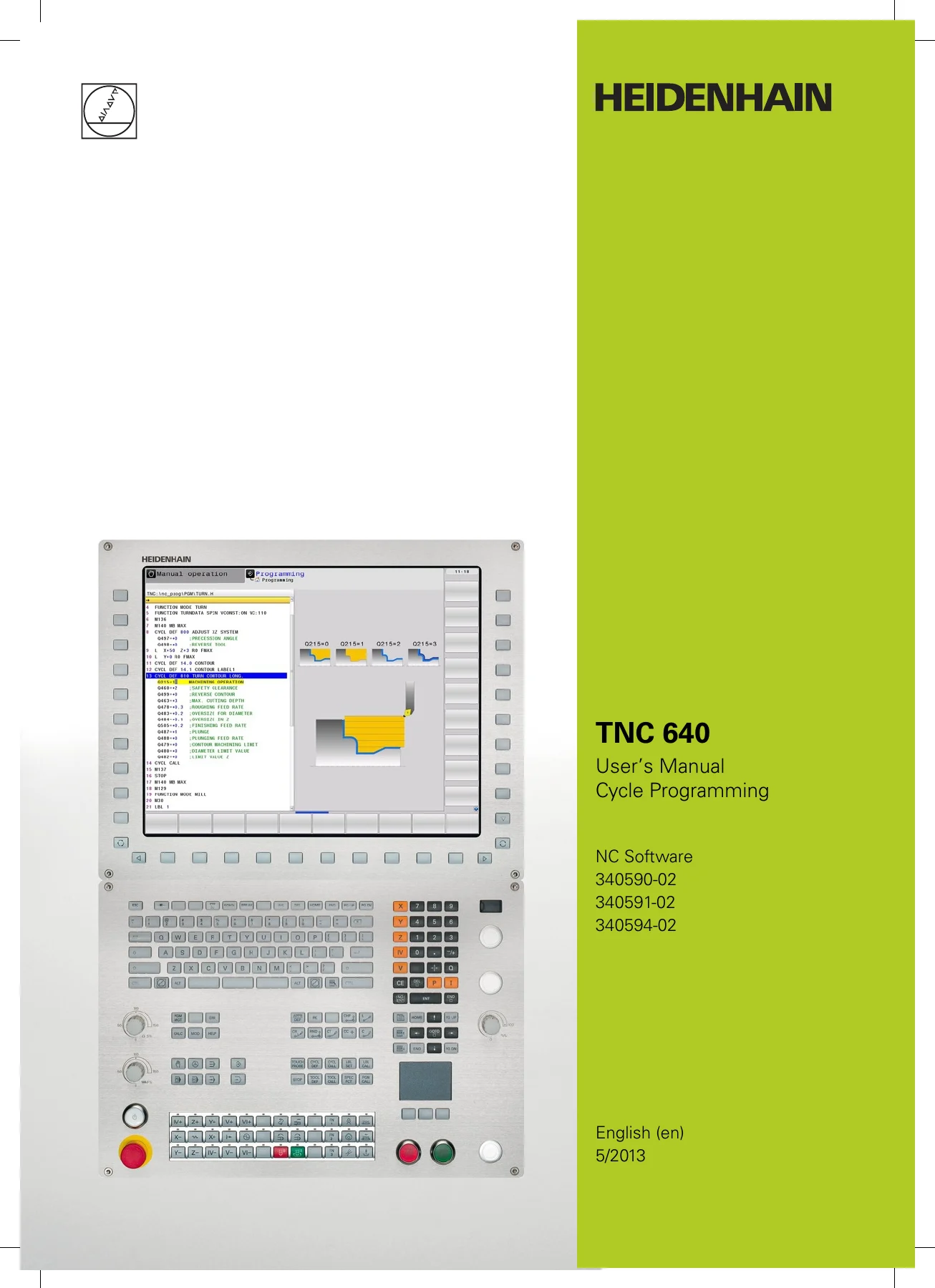
HEIDENHAIN TNC 640 Cycle Programming User Manual 340590-02 340591-02 340594-02
Original price was: $39.95.$24.95Current price is: $24.95.
Complete HEIDENHAIN Cycle Programming User’s Manual for the TNC 640, TNC 640 E and TNC 640 Programming Station (NC software 340590-02, 340591-02, 340594-02). Every fixed cycle, turning cycle and touch probe cycle documented with Q-parameter dialogs, cycle-run sequences and help graphics in a 581-page English PDF.
Description
HEIDENHAIN TNC 640 Cycle Programming User Manual – NC Software 340590-02 / 340591-02 / 340594-02
This is the HEIDENHAIN Cycle Programming User’s Manual for the TNC 640 contouring control, dated 5/2013 and written for NC software 340590-02 (TNC 640), 340591-02 (TNC 640 E) and 340594-02 (TNC 640 Programming Station). It is the reference that sits beside the machine when a cycle has to be defined, checked and run: each cycle is presented with its cycle run described step by step, the full Q-parameter dialog with input ranges, the help graphic that appears in the right-hand screen window during definition, and the collision warnings that must be read before the cycle is called.
Whereas the conversational programming manual covers linear and FK path functions, program structure, tool data and Q-parameter programming, this volume deals exclusively with the cycle side of the control – the canned machining operations, the coordinate transformations, the special functions and the entire touch probe cycle range. All 21 chapters are present in English, together with the closing table of cycles that lists every cycle number, whether it is DEF active or CALL active, and the page it is documented on.
File Details
- Manual type: User’s Manual – Cycle Programming
- Manufacturer: HEIDENHAIN
- Control models: TNC 640, TNC 640 E, TNC 640 Programming Station
- NC software numbers: 340590-02, 340591-02, 340594-02
- Document ID: 892905-21
- Edition / date: Ver01, SW02, 5/2013
- Language: English (en)
- Format: PDF
- Extent: 581 pages, 21 chapters plus cycle tables and index
What the Fixed Cycle Chapters Contain
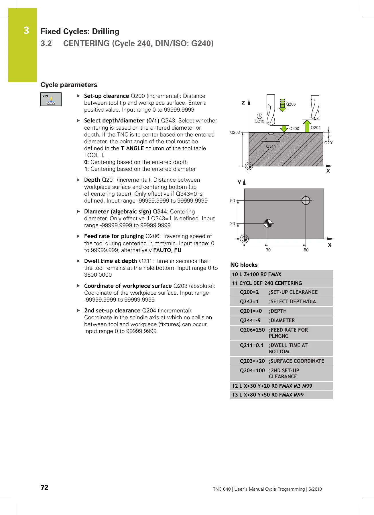
The drilling group runs from Cycle 240 Centering through Cycle 200 Drilling, 201 Reaming, 202 Boring, 203 Universal Drilling, 204 Back Boring, 205 Universal Pecking, 208 Bore Milling and 241 Single-Lip Deep-Hole Drilling. Each one gives the sequence of moves – prepositioning at FMAX to the set-up clearance, the plunge, any dwell at depth, chip breaking or retraction – and then the parameter table with Q200 set-up clearance, Q201 depth, Q206 plunging feed rate, Q202 plunging depth, Q203 workpiece surface, Q204 second set-up clearance and the cycle-specific values such as Q343 depth/diameter selection for centering, Q214 disengaging direction for boring, or Q379 deepened starting point for pecking.
The tapping and thread milling group covers Cycle 206 Tapping New with a floating tap holder, Cycle 207 Rigid Tapping without a floating tap holder, Cycle 209 Tapping with Chip Breaking, and then the thread milling family – 262 Thread Milling, 263 Thread Milling/Countersinking, 264 Thread Drilling/Milling, 265 Helical Thread Drilling/Milling and 267 Outside Thread Milling. A dedicated fundamentals section explains the interaction of pitch sign, climb or up-cut selection Q351 and spindle direction, because the working direction of the thread is derived from those three inputs rather than set directly.
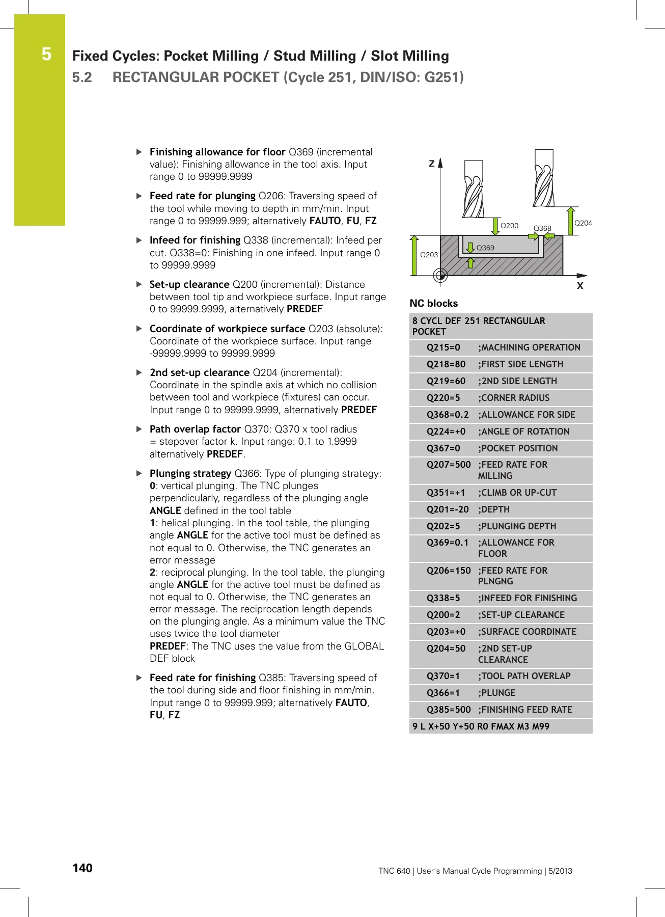
Pocket, stud and slot milling is handled by Cycles 251 Rectangular Pocket, 252 Circular Pocket, 253 Slot Milling, 254 Circular Slot, 256 Rectangular Stud and 257 Circular Stud. These are complete-machining cycles: one definition can rough, finish the floor and finish the side, or any single one of those operations, with the overlap factor Q370, side allowance Q368, floor allowance Q369 and the plunging strategy Q366 controlling how the tool enters the material. The contour pocket chapters that follow work differently – Cycles 14 Contour Geometry and 20 Contour Data define subcontours and machining data, and Cycles 21 Pilot Drilling, 22 Rough-Out, 23 Floor Finishing, 24 Side Finishing and 25 Contour Train then machine them. The manual explains how overlapping pockets and islands are superimposed, how inclusion, exclusion and intersection areas are built, and how the contour formula extends this to twelve subcontours in the SL cycle set.
Multipass milling – Cycle 230 Multipass Milling, 231 Ruled Surface and 232 Face Milling – is documented with the three face-milling strategies Q389=0, 1 and 2, each with its own stepover and retraction behaviour. The cylinder surface cycles 27, 28 and 29 roll a two-dimensional contour onto a cylinder and are marked as requiring software option 1.
Coordinate Transformations, Special Functions and Turning
Chapter 11 documents the transformations that reposition an already-programmed contour: Cycle 7 Datum Shift, datum shift from datum tables, Cycle 247 Datum Setting, Cycle 8 Mirroring, Cycle 10 Rotation, Cycle 11 Scaling, Cycle 26 Axis-Specific Scaling and Cycle 19 Working Plane. The order in which transformations are defined and reset is set out explicitly, along with the note that Cycle 19 requires software option 1 and that changes to the working plane affect the active datum.
Chapter 12 covers Dwell Time (Cycle 9), Program Call (Cycle 12), Spindle Orientation (Cycle 13), Tolerance (Cycle 32) and Engraving (Cycle 225), including the allowed engraving characters, the non-printable formatting characters and the % system variable syntax for engraving date and other system values.
The turning chapter is the largest single addition in this software version and is tied to software option 50. It opens with the two rotary coordinate system cycles 800 and 801, then works through longitudinal turning (811, 812, 813, 814, 810, 815), face turning (821, 822, 823, 824, 820) and the recessing cycles (841, 842, 840, 851, 852, 850, 861, 862, 860, 871, 872, 870), finishing with the three thread cycles 831, 832 and 830. Every turning cycle shares a common parameter block – Q215 machining operation, Q460 set-up clearance, Q463 maximum cutting depth, Q478 roughing feed rate, Q483 diameter oversize, Q484 Z oversize and Q505 finishing feed rate – so a programmer who learns one cycle reads the rest quickly. Blank form update (FUNCTION TURNDATA) is also explained here, since it lets the control recognise already-machined areas and shorten the approach and departure paths for subsequent tools.
Touch Probe Cycles
Five chapters are devoted to probing. Cycles 400 to 405 measure and compensate workpiece misalignment, either by setting a basic rotation or by rotating the rotary table, with Q402 selecting which. Cycles 408 to 419 set datums from slots, ridges, rectangles, circles, corners, bolt hole circles, the touch probe axis itself or any single axis, and they share the Q303/Q305 logic that decides whether the result goes to the display, the datum table or the preset table. Cycles 0, 1 and 420 to 431 inspect the workpiece – angle, hole, circular stud, rectangular pocket, rectangular stud, inside width, ridge width, any coordinate, bolt hole circle and plane – with tolerance bands, measuring logs, program stop on error and tool monitoring. Cycles 3 and 460 to 463 cover the special measuring function and touch probe calibration on a ring, a stud or a sphere. The KinematicsOpt cycles 450, 451 and 452 are documented with the measuring point selection guidance, Hirth coupling notes, backlash measurement and the logging function. Finally, Cycles 30/480, 484, 31/481, 32/482 and 33/483 handle automatic tool measurement on the TT touch probe, including the tool table entries CUT, LTOL, RTOL, R_OFFS, L_OFFS, LBREAK and RBREAK that the cycles read.
Chapters Covered
- 1 Fundamentals / Overviews – introduction, available cycle groups, fixed cycle and touch probe cycle overview
- 2 Using Fixed Cycles – machine-specific cycles, defining a cycle by soft key or GOTO, calling with CYCL CALL, CYCL CALL PAT, CYCL CALL POS, M99/M89, GLOBAL DEF program defaults, PATTERN DEF, point tables
- 3 Fixed Cycles: Drilling – 240, 200, 201, 202, 203, 204, 205, 208, 241, programming examples
- 4 Fixed Cycles: Tapping / Thread Milling – 206, 207, 209, fundamentals of thread milling, 262, 263, 264, 265, 267, programming example
- 5 Fixed Cycles: Pocket Milling / Stud Milling / Slot Milling – 251, 252, 253, 254, 256, 257, programming example
- 6 Fixed Cycles: Pattern Definitions – 220 Circular Pattern, 221 Linear Pattern, polar hole pattern example
- 7 Fixed Cycles: Contour Pocket – SL cycles, 14, superimposed contours, 20, 21, 22, 23, 24, 25, programming examples
- 8 Fixed Cycles: Cylindrical Surface – 27, 28, 29, programming examples
- 9 Fixed Cycles: Contour Pocket with Contour Formula – complex and simple contour formula, SEL CONTOUR, DECLARE CONTOUR
- 10 Fixed Cycles: Multipass Milling – 230, 231, 232, programming example
- 11 Cycles: Coordinate Transformations – 7, datum tables, 247, 8, 10, 11, 26, 19, programming example
- 12 Cycles: Special Functions – 9, 12, 13, 32, 225
- 13 Cycles: Turning – 800, 801, turning fundamentals, 811, 812, 813, 814, 810, 815, 821, 822, 823, 824, 820, 841, 842, 840, 851, 852, 850, 861, 862, 860, 871, 872, 870, 831, 832, 830, example program
- 14 Using Touch Probe Cycles – general information, preparation, touch probe table
- 15 Automatic Measurement of Workpiece Misalignment – 400, 401, 402, 403, 404, 405, example
- 16 Automatic Datum Setting – 408, 409, 410, 411, 412, 413, 414, 415, 416, 417, 418, 419, examples
- 17 Automatic Workpiece Inspection – 0, 1, 420, 421, 422, 423, 424, 425, 426, 427, 430, 431, programming examples
- 18 Touch Probe Cycles: Special Functions – Cycle 3, calibration cycles 460, 461, 462, 463
- 19 Automatic Kinematics Measurement – 450, 451, 452, prerequisites, Hirth-coupled axes, backlash, logging
- 20 Automatic Tool Measurement – 30/480, 484, 31/481, 32/482, 33/483, tool table entries, machine parameter notes
- 21 Tables of Cycles – fixed cycles, turning cycles, touch probe cycles with DEF/CALL status and page references
Taken as a whole, the document is a programming reference rather than a tutorial. The reader is expected to know how to call a tool, set a datum and write a positioning block; what this manual supplies is the exact behaviour of each cycle, the parameter dialog in the order the control asks for it, and the cautions that prevent a cycle from being run into a fixture, a vice or the table. The GLOBAL DEF chapter is worth noting on its own account, because it lets a shop define set-up clearance, 2nd set-up clearance, positioning feed rate and retraction feed rate once at the top of a program and then reference them with PREDEF in every subsequent cycle definition instead of typing the same numbers repeatedly.
Why This Cycle Programming Manual Belongs at the Machine
The TNC 640 will execute a cycle with any syntactically valid parameter set, which is precisely why the parameter descriptions matter. A depth entered with the wrong algebraic sign reverses the working direction; a 2nd set-up clearance set too low turns a chip-clearing retraction into a collision; a plunge strategy chosen without checking the tool table ANGLE and LCUTS columns produces an error message at the machine instead of a cut. Every one of those conditions is described in this manual, cycle by cycle, in the same wording the control uses on screen, so the operator can match the paper reference to the dialog in front of them.
The same applies to the probe side. The datum-setting cycles 408 to 419 write their results to the display, to the datum table or to the preset table depending on Q303 and Q305, and choosing the wrong combination silently places the datum where it was not wanted. The manual spells out the consequence of each combination, and it sets out the touch probe table columns – CAL_OF1, CAL_OF2, CAL_ANG, F, FMAX, DIST, SET_UP, F_PREPOS and TRACK – that govern how the probe behaves before the cycle is ever called. For shops running 5-axis work, the KinematicsOpt chapters provide the measuring point and calibration sphere placement guidance needed to get a usable optimisation result rather than a scatter of values.
Because the volume is delivered as a PDF, it can be kept on the control room PC, opened on a tablet at the machine, printed for the tool crib, or searched by cycle number when a parameter dialog needs to be checked mid-setup. There is no shipping delay and no separate disc to lose – the file is available immediately after payment and can be read on any device that opens a PDF.
IMAGES PREVIEW
Reviews
There are no reviews yet.