
Hill-Rom Advanta P1600 Bed Service Manual – Troubleshooting, Repair & Parts Guide PDF
Original price was: $39.95.$24.95Current price is: $24.95.
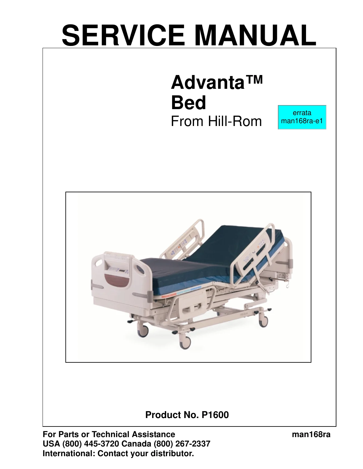
The complete Hill-Rom Advanta P1600 Bed Service Manual (man168ra) covering troubleshooting, theory of operation, removal/replacement procedures, parts lists, and preventive maintenance for P1600A and P1600B hospital beds. 429 pages of detailed technical documentation including wiring diagrams, error code diagnostics, and step-by-step repair instructions.
Description
Hill-Rom Advanta P1600 Bed Service Manual – Complete Troubleshooting, Repair & Parts Guide
This is the full service manual for the Hill-Rom Advanta Bed, models P1600A and P1600B. Published in 2001 as the Second Edition (Revision A), document number man168ra, this 429-page PDF is the comprehensive technical resource used by facility-authorized service personnel to troubleshoot, repair, and maintain the Advanta hospital bed platform.
File Details
- Manual Type: Service Manual
- Brand: Hill-Rom
- Model: Advanta P1600 (P1600A, P1600B)
- Document Number: man168ra
- Edition: Second Edition
- Revision: Revision A (May 2001)
- Original Issue: April 2000
- Language: English
- Page Count: 429 pages
- File Format: PDF
Chapters Covered
- Chapter 1: Introduction – Purpose, Audience, Organization, Typographical Conventions, Overview, Operating Precautions, Features (Head Section Inclination, Automatic Contour, Articulating Frame, Knee Section Inclination, Foot Section Inclination, Hilow Sleeping Surface, Trendelenburg/Reverse Trendelenburg, Chair Position, CPR Release, Casters, Central Brake and Steer, Manual Operation, Headboard and Footboard, IV Rod Accommodation, Bed Frame, Docking/Wall Protection, Siderails, ZoneAire Sleep Surface, Mattress Components, Bed Positions, Specifications, Electrical Description, Motors, Limit Switches, Regulations/Standards/Codes, Model Identification, General Operation, Siderail Controls and Footboard Control Panel, Standard Controls, Optional Controls, Indicators, Safety Tips, Service and Maintenance, Warning and Caution Labels
- Chapter 2: Troubleshooting Procedures – Getting Started, Test Equipment, Initial Actions, Function Checks, Mechanical Subsystem Troubleshooting, Electrical Subsystem Troubleshooting, Pneumatic Subsystem Troubleshooting, PPM Function Check, Service Required LED, Footboard Control Panel Switch/LED Test, Air System Self-Diagnostic Test, Air System Independent Diagnostic Test, Soft Reset, Final Actions, Head Hilow Does Not Lower/Go Up, Foot Hilow Does Not Lower/Go Up, Knee Section Does Not Lower/Go Up, Head Section Does Not Lower/Go Up, Trendelenburg/Reverse Trendelenburg RAPs, Night Light Does Not Operate, ZoneAire Sleep Surface Error Codes 2-1 through 2-7 (Slow Leak, Continuous Run, Triac Short, Sensor EEPROM, Mattress Disconnected, Triac Open, LON Communication Error), Key Stuck Closed Error Code 1-2, ZoneAire Sleep Surface Does Not Work, Scale Display Errors (Err0, Err1, Err2, Err3), PPM Does Not Function, PPM System Beeps Twice and Flashes LEDs, SideCom Communication System Tester
- Chapter 3: Theory of Operation – Wiring Diagrams, Logic Control P.C. Board (P/N 63285), Power Supply P.C. Board (P/N 63349), Patient Position Monitor (PPM), Air Control P.C. Board (P/N 44760), Echelon Node, Latches and Buffers, Valve/Sensor Module Digital Control Lines, External Watchdog, 24V AC Solenoid Drivers, Compressor and Crossover Valve Drivers, Electrostatic Discharge (ESD) Protection, LON Connector, Regulator, Line Input Power, Sensor Control Board (P/N 44740), General Description, Input Protection, Output Protection, EEPROM, Digital-to-Analog Converter, Analog Multiplexer, Amplifier, Analog-to-Digital Converter, Solenoid Drive, Grounds, Power Supply, ZoneAire Sleep Surface Air Interface System, Switch Matrix, Membrane Key Panel Switch Multiplex Circuit, LEDs, Membrane Key Panel LED Driver, ZoneAire Sleep Surface Mattress Plumbing, ZoneAire Sleep Surface Software Theory of Operation (General Description, Reset, Operating Modes, Off Mode, Pressure Relief Mode, Heel Relief Modes, Auto Firm Mode, CPR Mode, Mode Transition, Power Up, Intermode Transitions, Power Down, System Errors)
- Chapter 4: Removal, Replacement, and Adjustment Procedures – Footboard, Foot End Cover, Headboard, Head End Covers, Air Control Cover, Air Sleep Surface Mattress, Air Sleep Surface Sensor Control P.C. Board, Air Sleep Surface Surface Control Valve, Air Sleep Surface Air Control P.C. Board, Air Sleep Surface Switching Valve Assembly, Air Sleep Surface Transformer, Air Sleep Surface Compressor, Footboard Control Panel P.C. Boards and Cables, Motor Cover Assembly, Night Light Bulb, Cable Conduit and Cable Assembly, Head Motor, Hilow Head Motor, Hilow Foot Motor, Knee Motor, Head Drive Screw Assembly, Hilow Head Drive Screw Assembly, Head Limit Switch, Hilow Head Limit Switch, Knee Drive Screw Assembly, Knee Limit Switch, CPR Release Handle, CPR Limit Switch, Hilow Foot Drive Screw Assembly, Hilow Foot Limit Switch, Brake Light Switch, Siderail Controls and Speakers, Siderails, Power Supply Control P.C. Board, Logic Control P.C. Board, Footboard Interface P.C. Board, Scale/PPM Control P.C. Board, Weigh Load Beam, Patient Position Monitor (PPM) Sensor, Junction Box P.C. Board
- Chapter 5: Parts List – Warranty, Service Parts Ordering, Exchange Policy, Recommended Spare Parts, Base Frame Assembly, Weigh Frame Assembly, Intermediate Frame Assembly, Retracting Frame Assembly, Cover Assemblies, CPR Release, PPM Sensors, Air Surface Control Module Mattress, Air Surface Control Module Frame, Air Supply Module, Foot End Siderail, Left Head End Siderail, Right Head End Siderail, Communication J-Box, Footboard P1606, Head and Foot Hilow Drive Assembly, Head Drive Screw Assembly, Knee Drive Screw Assembly, COMposer Interface Module, Power Module, Electronics Module Assembly, Headboard Assembly P1605, Accessory Outlet Module, ZoneAire Sleep Surface Mattress P1410CA/P1410EA, Permanent IV Rod P2221
- Chapter 6: General Procedures – Scale Calibration, Cleaning, Steam Cleaning, Cleaning Hard to Clean Spots, Disinfecting, Component Handling, P.C. Boards, Lubrication Requirements, Preventive Maintenance, Preventive Maintenance Schedule, Preventive Maintenance Checklist, Preventive Maintenance ZoneAire Sleep Surface, Preventive Maintenance Schedule ZoneAire Sleep Surface, Preventive Maintenance Checklist ZoneAire Sleep Surface, Tool and Supply Requirements
- Chapter 7: Accessories – Accessories List, ZoneAire Sleep Surface Mattress P1410CA01/P1410CA02/P1410EA01/P1410EA02, Bed Extender Assembly P9959, Installation of Lower Retracting Frame, Removal of Lower Retracting Frame, Installation of Upper Retracting Frame, Removal of Upper Retracting Frame
This Hill-Rom Advanta P1600 Bed service manual provides the complete technical foundation for maintaining and repairing the Advanta bed platform. From the four-motor articulation system and retractable frame design to the ZoneAire air sleep surface, PPM bed-exit monitoring, and integrated scale system, every major subsystem is documented with theory of operation, diagnostic flowcharts, and step-by-step removal/replacement procedures. The wiring diagrams and fold-out schematics cover the logic control board, power supply board, air control board, sensor board, and all interconnecting cables, giving technicians the schematics needed to trace faults down to the component level.
What This Hill-Rom Advanta P1600 Service Manual Enables You to Do
- Diagnose and repair all bed articulation functions – head, knee, hilow (head and foot), Trendelenburg, Reverse Trendelenburg, and chair position
- Troubleshoot the ZoneAire Sleep Surface using error codes 2-1 through 2-7, including slow leak, continuous run, triac short/open, EEPROM, mattress disconnected, and LON communication errors
- Service the PPM (Patient Position Monitor) system and resolve arming failures, sensor faults, and zeroing procedures
- Calibrate the bed scale and resolve Err0 through Err3 display faults
- Remove and replace every major component – motors, drive screws, limit switches, P.C. boards, transformers, compressors, switching valves, load beams, and sensors
- Perform preventive maintenance on both the bed frame and ZoneAire Sleep Surface to JCAHO standards
- Identify and order correct replacement parts using the illustrated parts lists and part numbers
- Understand the electrical and pneumatic theory of operation for systematic troubleshooting
- Test the SideCom Communication System using the dedicated tester procedure
- Adjust the CPR release handle and verify proper cable tension
- Service the central brake and steer system, casters, and brake light switch
- Maintain the bed’s electrical safety through leakage current and ground resistance testing
Why the Hill-Rom Advanta P1600 Bed Service Manual Matters
Hospital bed service work demands precision. An improperly adjusted limit switch, a misaligned drive screw, or an incorrectly calibrated scale can affect patient safety and bed reliability. This manual provides the exact procedures, torque values, voltage measurements, resistance checks, and adjustment specifications needed to perform repairs correctly the first time. The troubleshooting flowcharts walk through symptoms methodically – from “Head Hilow Does Not Lower” to “ZoneAire Sleep Surface Triac Open” – so you can isolate faults efficiently rather than guessing. Each removal and replacement procedure includes tool requirements, safety warnings, step-by-step instructions, and reassembly notes to prevent equipment damage.
Detailed Diagnostic Coverage
The troubleshooting chapter alone spans dozens of repair analysis procedures (RAPs). Each RAP begins with initial actions, proceeds through voltage and resistance measurements at specific connector pins, and concludes with a component replacement or adjustment recommendation. For the ZoneAire Sleep Surface, the manual decodes the Service Required LED flash patterns – long and short flashes – into specific fault codes with corresponding corrective actions. The PPM section covers zeroing procedures for beds with and without scales, mode activation, alarm cancellation, and volume/tone adjustment. The scale section addresses calibration, zeroing, changing items, and unit conversion.
Parts Identification Made Simple
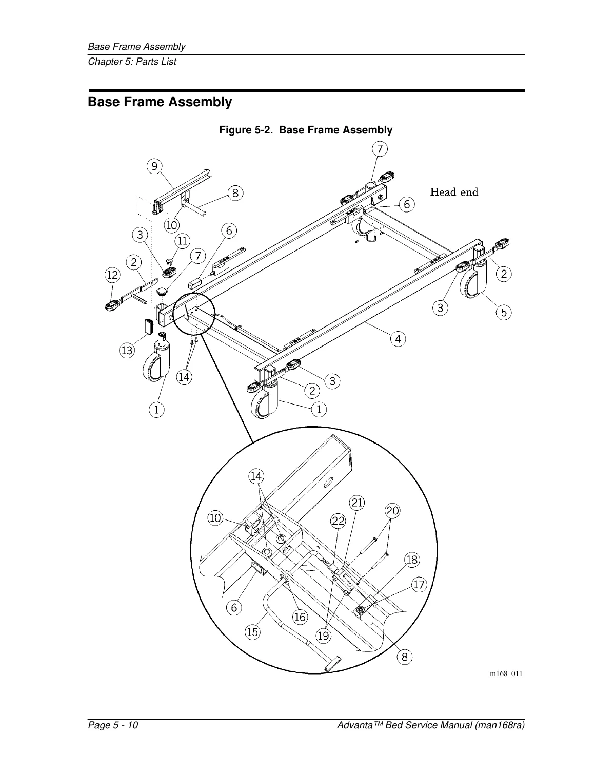
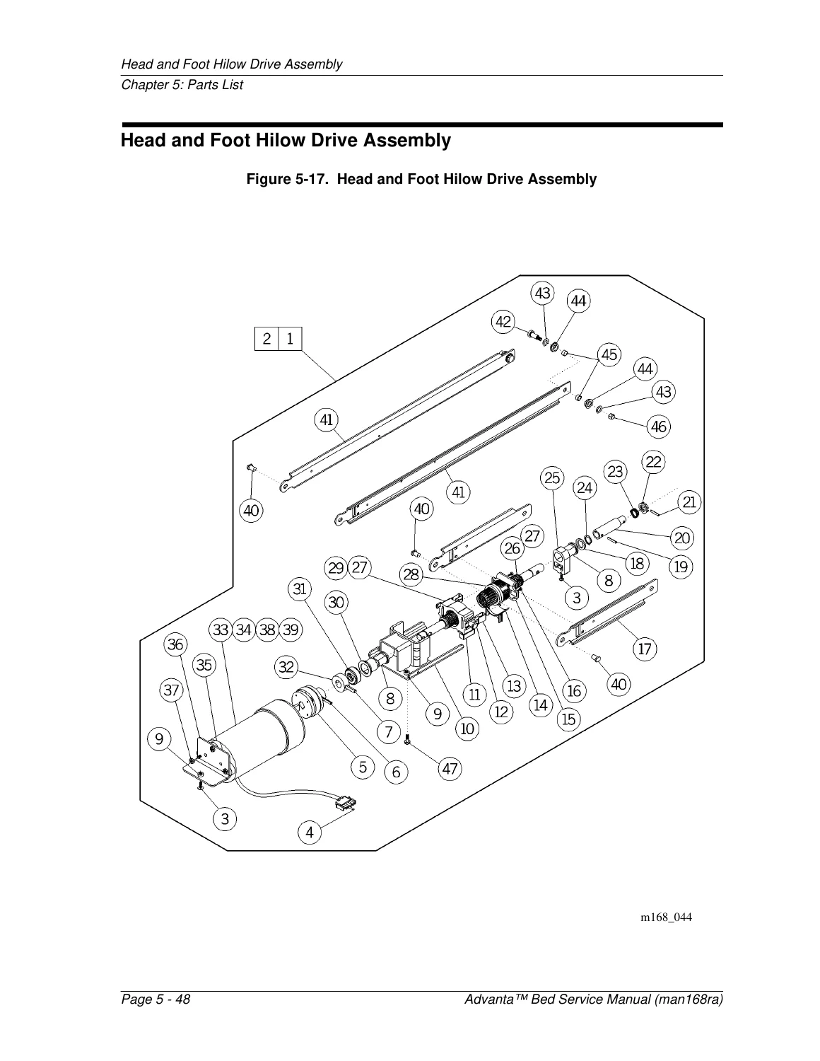
Chapter 5 contains illustrated parts lists with exploded-view diagrams for every major assembly. Each part is identified by item number, part number, quantity, and description. Whether you need a replacement caster, a logic control P.C. board, a head drive screw assembly, or a ZoneAire mattress component, the parts lists cross-reference directly to the removal and replacement procedures in Chapter 4. The recommended spare parts table helps facilities stock critical components for five or more beds.
Delivery
IMAGES PREVIEW
This Hill-Rom Advanta P1600 Bed service manual is delivered as an instant PDF download after payment. No shipping, no waiting. The file works on any device – computer, tablet, or smartphone – and can be printed for use in the workshop or at the bedside. Keep it on hand for reference during every repair or maintenance task on your Advanta P1600A or P1600B bed.


Reviews
There are no reviews yet.