
Manitou MLT & MLT-X Telehandlers Service Manual 647681EN 2022 – PDF Download
Original price was: $36.95.$22.95Current price is: $22.95.
Complete Manitou service manual for the MLT and MLT-X telehandler range, document 647681EN, updated 2022. Covers nine machine variants across the MLT 635, 733, 737, 741, 940 and MLT-X 737, 741 families. Engine, transmission, axle, brakes, boom, hydraulics, electrical, cab, chassis and options. 512-page PDF download.
Description
Manitou MLT & MLT-X Telehandlers Service Manual — 647681EN, 2022 Edition
This is the complete Manitou service manual for the MLT and MLT-X range of telehandlers, published under document number 647681EN and last updated on 04/03/2022. It covers nine machine variants across the MLT 635, 733, 737, 741 and 940 families, plus the MLT-X 737 and 741 models. The manual is structured as an interactive repair manual, providing the full range of service, repair and diagnostic procedures needed to keep these machines working correctly — from engine and transmission overhauls down to brake bleeding, boom pad adjustment and electrical fault code lookup.
File Details
- Manual type: Service Manual (Interactive Repair Manual)
- Brand: Manitou
- Document number: 647681EN
- Publication date: 04/03/2022
- First edition: 09/01/2018
- Language: English
- Page count: 512
- File format: PDF
Models Covered
- MLT 635 130 PS D ST4 S2
- MLT 635 140 V PLUS D ST4 S2
- MLT 733 105 D ST4 S2 + TRACT + LSU
- MLT 733 115 D ST4 S3 + TRACT + LSU
- MLT 737 130 PS D ST4 S2
- MLT 741 140 V PLUS D ST4 S2
- MLT 940 140 V PLUS D ST4 S2
- MLT-X 737 130 PS D ST3A S1
- MLT-X 741 140 V PLUS D ST3A S1
Chapters Covered
The manual is organised into numbered groups, each with its own table of contents and cross-referenced procedures:
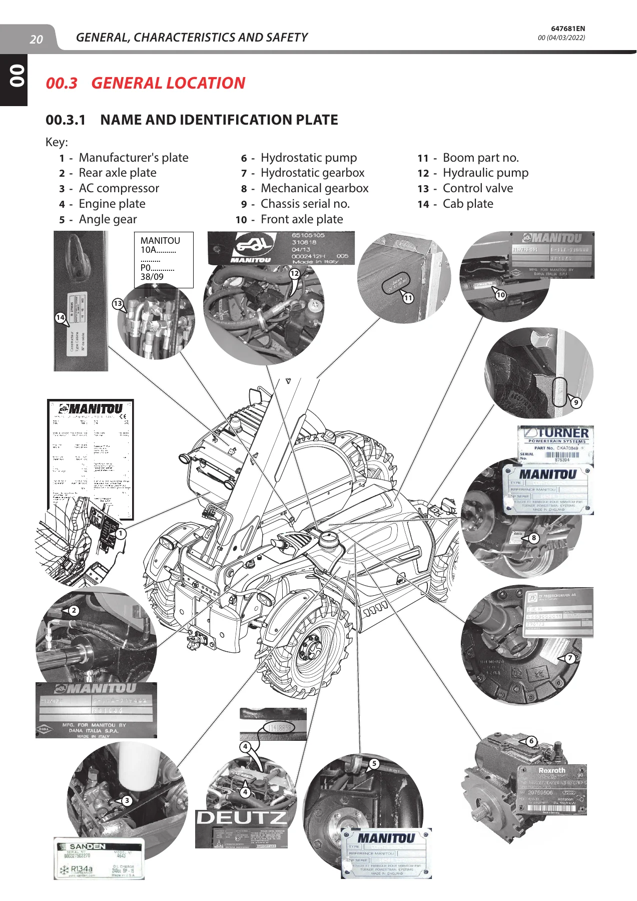
- 00 — General: safety instructions, servicing position and rules, specifications, lubricants and fuel, dimensions, identification plates, standard tightening torques, metric-imperial conversion
- 10 — Engine: engine characteristics, DEF (Diesel Exhaust Fluid), injection cycle, Bosch CP4.1 high pressure pump, air intake and EGR circuits, lubrication, cooling, fuel system, DEF circuit, component locations, engine start-up conditions, DEF regeneration, fan regulation, tightening torques for engine suspension and couplings, engine removal and refit, ECU removal, air filter, starter motor, DOC/SCR pipes, DEF injector and tank, cooler removal, alternator, water pump, turbo-compressor, troubleshooting, special engine tooling
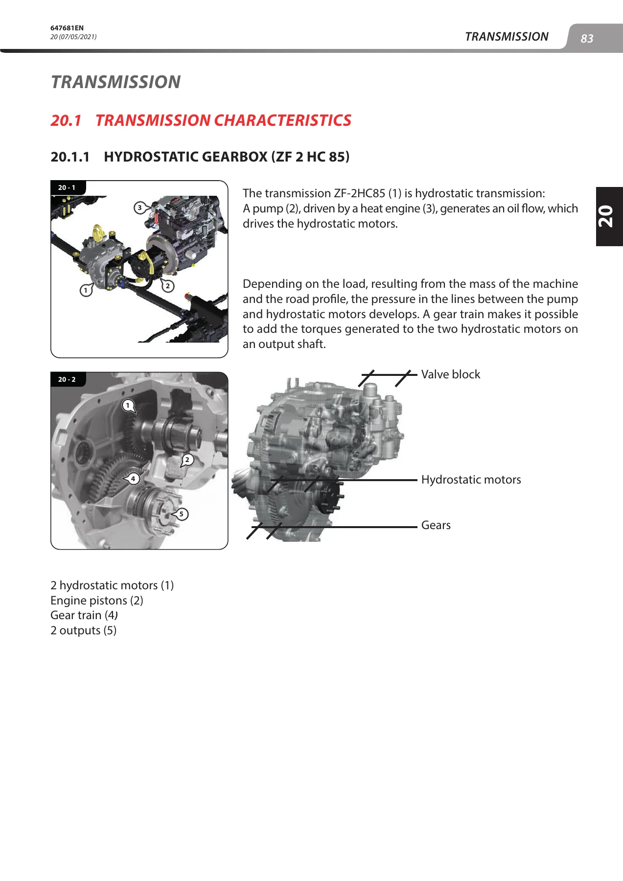
- 20 — Transmission: ZF 2 HC 85 hydrostatic gearbox characteristics and operation, Compact+ manual gearbox, Powershift PG 115 gearbox, drive train schematics, transmission locations, authorisation conditions for carriage movement, hydrostatic auto-calibration, pressure testing, transmission tightening torques, freewheel mode, Powershift and hydrostatic gearbox removal, manual gearbox assembly removal, hydrostatic pump removal, specific transmission tooling
- 30 — Axle: axle stops adjustment, rear axle pin adjustment clearance, tightening torques
- 40 — Brakes: service brake specifications, trailer brake valve, accumulator load valve, service brake valve 55 B, automatic parking brake option, pneumatic trailer braking option, brake valve operating principle, brake locations, trailer brake valve tightening torque, parking brake adjustment on gearbox and front axle, brake pedal adjustment, inching pedal calibration, brake bleeding, towing, master cylinder removal, brake fluid bleeder
- 50 — Boom: duplex and triplex boom characteristics, boom locations, telescope extension and retraction adjustment, shim fitting and lubrication recommendations, duplex and triplex tightening torques and lubrication, duplex boom telescope and telescopic cylinder removal, triplex boom telescoping circuit removal, boom head telescope T2 and intermediate telescope T1 removal, special boom tools
- 70 — Hydraulics: dynamic steering operation, hydraulic component sheets (accumulator block, OSPC 200 LS steering block, pilot safety valve, RS 14 distributor, SDS 140 distributor, fan regulator motor, Casappa MVP 60-63 pump, LA10V072EK1DS/53R pump, steering selector, automatic steering selector), hydraulic schematic diagrams for each MLT/MLT-X model, hydraulic locations, controls and adjustments, hydraulic pump, lifting cylinder and distributor removal, hydraulic specific tooling
- 80 — Electricity: relay and fuse locations, screen menus, electrical network architecture, ECU inputs/outputs (screen, navigator, air-conditioning ECU, main ECU SPU 40-26, engine ECU EDC17CV52, Powershift ECU, auxiliary ECU SPU 25-15, CVT ECU), technical sheets for electrical components, wiring diagrams by model and function, electricity locations, electrical control and adjustment, battery and ECU removal, strain gage refitting, electrical troubleshooting, DTC error codes, specific electric tooling
- 85 — Driver’s Cab: tightening torques, door opening/closing control adjustment, cab removal, windshield removal, window winder removal, cab door removal, windshield wiper motor removal, cab lower trim removal, upper dashboard removal, heating unit removal, driver’s seat removal, armrest removal, dashboard switch removal, cab grille hinge kit
- 90 — Chassis-Bodywork: engine hood removal
- 110 — Options-Attachments: intelligent hydraulics option, regenerative hydraulics option, boom suspension option, automatic parking brake option, pneumatic trailer braking option, optional automatic central greasing, camera option, engine Eco-Stop option, air conditioning option, troubleshooting for each option
Across these groups, the manual gives a technician the complete working reference for the MLT and MLT-X telehandler platforms — not just a list of procedures, but the underlying specifications, tightening torques, pressure values, electrical pinouts and diagnostic code tables that make those procedures safe and repeatable. Engine work on the Deutz TCD 3.6 L4 and TD 3.6 L4 power units, hydrostatic and Powershift transmission service, boom telescoping adjustment, hydraulic distributor overhaul and full electrical diagnostics are all supported in depth.
Engine and Powertrain Coverage in Detail
The engine section begins with the Deutz 3.6-litre four-cylinder unit used across the range, listing the compression ratio of 17.2, maximum power output of 100 kW (136 hp), maximum torque of 500 N.m at 1,600 rpm, and the minimum, nominal laden and maximum unladen engine speeds. The after-treatment system is fully described, including the DOC, DPF, SCR and AOC components, the DEF circuit and pump, regeneration conditions and the degraded-mode torque and speed reduction logic that applies if DEF quality or level is not maintained. The Bosch CP4.1 high pressure pump is covered with its MPROP valve, cam follower wear points and pressure relief valve behaviour. The manual also documents the EGR circuit, the turbocharger and air cooler, the lubrication and cooling systems and the diesel fuel circuit, with tightening torques for every major joint.
Transmission and Hydraulics
Three transmission types are covered: the ZF 2 HC 85 hydrostatic (CVT) gearbox with its two radial hydrostatic motors and gear train, the Powershift PG 115 automatic gearbox and the Compact+ manual gearbox. The hydrostatic section explains the two driving modes (comfort and dynamic), the auto-calibration procedure, and the pressure connector readings a technician needs to diagnose pump and motor problems. The hydraulic section is similarly thorough, with component sheets for the RS 14 and SDS 140 distributors, the Casappa MVP 60-63 and LA10V072EK1DS/53R pumps, the OSPC 200 LS steering block and the pilot safety valves, plus schematic diagrams for each machine variant.
Electrical and Diagnostic Content
The electrical group documents the SPU 40-26 main ECU, SPU 25-15 auxiliary ECU, EDC17CV52 engine ECU, PG115 Powershift ECU and ZF 2HC85 CVT ECU, with full pinout tables, fuse and relay positions, wiring diagrams arranged by model and function, and a comprehensive DTC error code listing with SPN/FMI designations and fault descriptions. This makes the manual a working diagnostic tool as well as a repair guide — you can trace a fault from the dashboard code to the affected circuit and component.
What This Service Manual Enables You to Do
With this manual, you can carry out scheduled maintenance, diagnose faults, remove and refit major assemblies, overhaul components, adjust and calibrate systems, and verify your work against the manufacturer’s own figures. It covers engine removal, transmission removal and refit, brake adjustment and bleeding, boom telescope adjustment, hydraulic pump and distributor removal, cab removal and refitting, air conditioning service, central greasing system fault-finding, and much more. For anyone maintaining a Manitou MLT or MLT-X telehandler, it is the difference between guessing at a procedure and following the exact sequence and torque values the machine was designed around.
Why the Correct Procedures and Specifications Matter
Telehandlers are lifting machines, and incorrect assembly or adjustment can create real safety risks — whether that is an incorrectly adjusted parking brake, a boom telescope pad set with the wrong clearance, or a hydraulic pressure left outside specification. Using the correct tightening torques, pressure values and adjustment dimensions matters for more than reliability; it is part of keeping the machine safe to operate. This manual provides those values in a structured, searchable document rather than scattered notes.
Instant PDF Delivery
The manual is delivered as a PDF download immediately after purchase — no shipping, no waiting. It can be read on any device, printed for use in the workshop, and kept as a permanent reference. Whether you are a technician, a fleet operator or an owner maintaining your own machine, this Manitou MLT and MLT-X service manual gives you the full factory-level content in a convenient, portable format.

Reviews
There are no reviews yet.