
Hino J08E Shovel Diesel Engine Workshop Manual PDF – Complete Repair Guide
Original price was: $59.95.$39.95Current price is: $39.95.
Comprehensive 291-page Hino J08E diesel engine workshop manual for shovel applications. Covers engine mechanical, common rail fuel system, EGR, turbocharger, electrical, diagnostics with Hino-DX, and full specifications.
Description
Hino J08E Shovel Diesel Engine Workshop Manual
This Hino J08E Diesel Engine Workshop Manual is the complete service and repair guide for the J08E engine in shovel applications. Whether you are a professional diesel technician, a fleet maintenance manager, or an owner-operator performing your own repairs, this manual provides the procedures, specifications, and diagnostic guidance needed to keep the J08E running correctly.
The J08E is a common rail diesel engine featuring exhaust gas recirculation (EGR), a turbocharger, and an electronically controlled fuel system. This manual covers every major system in detail, from compression testing and cylinder head overhaul to fuel injector replacement, turbocharger inspection, and engine ECU diagnostics. With 291 pages of service information, it delivers the depth required for both routine maintenance and full engine overhauls.
File Details
- Manual Type: Workshop Manual
- Brand: Hino
- Model: J08E
- Application: Shovel Diesel Engine
- Language: English
- Page Count: 291 pages
- File Format: PDF
Chapters Covered
- 1. General
- 2. Standard Value
- 3. Parts to be Prepared
- 4. Engine Assembly/Disassembly
- 5. Fuel System
- 6. Emission Control
- 7. Electrical
- 8. Intake
- 9. Engine Mechanical
- 10. Exhaust
- 11. Cooling
- 12. Lubrication
- 13. Starting and Charging
- 14. Turbocharger
- 15. Failure Diagnosis for Each Engine Status
- 16. Engine Diagnosis Code
General, Standard Value & Parts to be Prepared (Chapters 1–3)
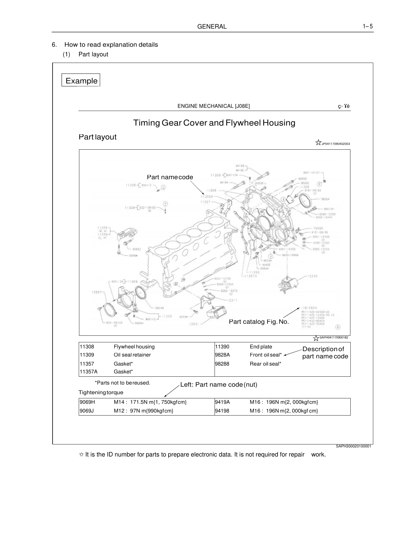
Chapter 1 covers how to read the manual, safety precautions, tightening procedures for engine bolts and nuts, flare nuts and hoses, taper thread sealant application, joint and gasket assembly, liquid gasket handling, and failure diagnosis using Hino-DX. Chapter 2 provides standard values, repair limits, service limits, and tightening torques for the engine body, fuel system, emission control, intake, engine mechanical, exhaust, cooling, lubrication, starting and charging, and turbocharger. Chapter 3 lists the special tools, instruments, and lubricants required for service, including compression gauge adapters, oil seal pullers and presses, valve spring presses, cylinder liner pullers, and piston ring expanders.
Engine Assembly/Disassembly (Chapter 4)
This chapter covers inspection before service, including measurement of compression pressure with preparation steps, standard values, and service limits. It details engine removal procedures including preliminary work, draining coolant and engine oil, disconnecting fuel hoses and water/oil pipes, and engine lifting. Installation and post-installation work such as fuel hose connection, engine oil inspection, and fuel system air bleeding are also included. Compression pressure is specified at 2.9–3.1 MPa (30–32 kgf/cm²) with a service limit of 2.3 MPa (24 kgf/cm²), measured at 150 r/min.
Fuel System & Emission Control (Chapters 5–6)
The fuel system chapter covers the common rail fuel system diagram, fuel filter drain and element replacement, supply pump replacement and inspection, injector replacement and inspection, and common rail replacement and inspection. The emission control chapter covers the EGR system, including EGR valve removal and installation, EGR cooler removal and installation, and EGR inspection with Hino-DX. Injector correction value entry using QR code reader and Hino field support system is also documented.
Electrical, Intake & Exhaust (Chapters 7–8, 10)
Electrical covers the electrical system part layout, component layout, inspection of components including oil pressure warning switch, coolant temperature sender gauge, glow plug, suction control valve, fuel temperature sensor, common rail pressure sensor, and injector. Installation of engine revolution sensors, starter, and alternator is covered along with V-belt tension adjustment. Intake covers the intake manifold and intake pipe removal and installation. Exhaust covers the exhaust manifold, including stud bolt replacement and installation with specified tightening sequences for new and reused manifolds.
Engine Mechanical (Chapter 9)
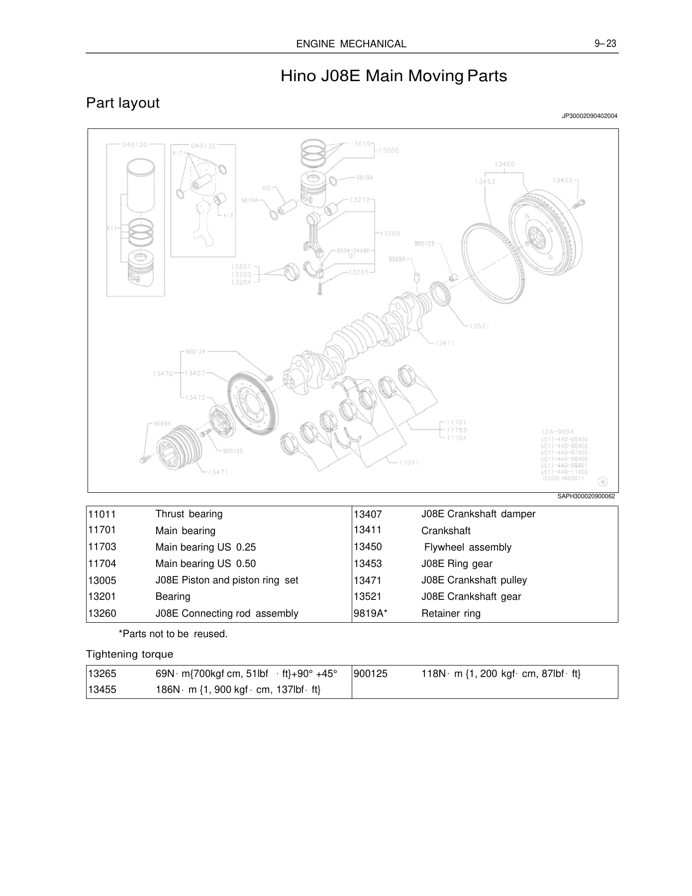
This is the largest chapter, covering cylinder head, cylinder block, timing gear cover and flywheel housing, main moving parts, camshaft and idle gears, and valve system. The cylinder head section covers replacement, overhaul, valve guide replacement, valve seat replacement, nozzle seat replacement, distortion inspection, and crack inspection. Cylinder block covers cylinder liner replacement, liner protrusion inspection, cooling jet inspection and adjustment, and block distortion and crack inspection. Main moving parts covers piston and connecting rod replacement, inspection, connecting rod bushing replacement, crankshaft replacement and inspection, crankshaft pulley replacement, and flywheel replacement. Camshaft and idle gears covers removal, disassembly, inspection, assembly, installation, timing gear layout, removal, inspection, and installation. Valve system covers rocker arm and shaft removal and installation, valve spring removal and installation, valve stem seal replacement, valve spring inspection, and valve clearance adjustment. Valve clearance (cold) is IN 0.30 mm and EX 0.45 mm.
Cooling, Lubrication, Starting & Charging (Chapters 11–13)
Cooling covers the cooling system drawing, thermostat case replacement, thermostat inspection, and coolant pump replacement. Thermostat valve opening temperature is 74.5–78.5°C (166.1–173.3°F). Lubrication covers the oil cooler, oil filter, and oil pump system drawing, part layouts, oil cooler replacement and overhaul, oil pump replacement and overhaul, oil strainer replacement, oil pan replacement, and inspection of lubrication status. Starting and charging covers starter disassembly, component inspection, assembly, and the alternator (60A) including part layout, circuit drawing, disassembly, inspection, assembly, and post-assembly inspection.
Turbocharger (Chapter 14)
Turbocharger covers the turbocharger assembly part layout, inspection of turbine shaft axial play using the special tool assembly (380100044), and replacement procedures. Turbine shaft play standard value is 0.040–0.085 mm (0.0016–0.0033 in.). Installation precautions for lubrication, cooling, air intake, and exhaust systems are documented.
Failure Diagnosis & Engine Diagnosis Codes (Chapters 15–16)
Chapter 15 provides failure diagnosis tables for each engine status, covering engine mechanical, alternator, starter, and turbocharger. Chapter 16 covers the engine ECU, precautions, system block diagram, inspection, Hino-DX connection method, failure code table, signal check harness, computer pin arrangement, ECU power supply voltage check, ground check, and detailed troubleshooting for every DTC code. This includes engine speed main and sub sensor circuits, coolant temperature sensor, engine overheat, engine overrun, fuel temperature sensor, boost pressure sensor, turbocharger over boost, common rail pressure, accelerator sensors, atmospheric pressure sensor, injector circuits, cylinder contribution/balance faults, SCV malfunction, supply pump, EGR solenoids and valves, EGR lift sensors, preheat circuit, injector correction data, ECU internal errors, main relay, idle volume, idle switch, and starter signal.
IMAGES PREVIEW
With this Hino J08E Shovel Diesel Engine Workshop Manual, you can confidently perform everything from a compression test to a full engine overhaul, diagnose faults using the factory diagnostic codes, and verify every repair against the correct specifications. The manual includes the tightening torques, service limits, and measurement procedures that prevent guesswork and ensure the engine is reassembled to specification. Delivered as an instant PDF download, it is printable and viewable on any device — no shipping, no waiting, no risk of missing pages.
Reviews
There are no reviews yet.